background image

INSTRUCTION MANUAL

MANUEL D’INSTRUCTIONS

MANUAL DE INSTRUCCIONES
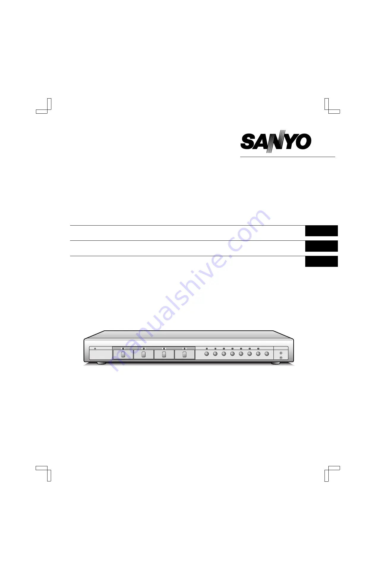
MPX-CD4
MPX-MD4

About this manual

Before installing and using this unit, please read this manual
carefully. Be sure to keep it handy for later reference.

This manual gives basic connections and operating
instructions for 2 models (Colour MPX-CD4, B/W MPX-MD4).

À propos de ce manuel

Avant d’installer et d’utiliser cet appareil, veuillez lire ce
manuel attentivement. Assurez-vous de le garder à portée
de la main pour référence ultérieure.

Ce manuel couvre les instructions de branchement et
d’utilisation de base pour deux modèles (couleur MPX-CD4,
noir et blanc MPX-MD4).

Acerca de este manual

Antes de instalar y usar este aparato, lea detenidamente
este manual. Asegúrese de guardarlo a mano para futuras
referencias.

Este manual le indica las conexiones básicas y las
instrucciones de funcionamiento de dos modelos (Color
MPX-CD4, Blanco y negro MPX-MD4).

Multiplexer

English

GB 

Multiplexeur

Français

Multiplexor

Español

L8FH5/US (MPX-CD4 GB) 1999. 6. 4

Summary of Contents for MPX-CD4

Page 1: ...e manuel attentivement Assurez vous de le garder à portée de la main pour référence ultérieure Ce manuel couvre les instructions de branchement et d utilisation de base pour deux modèles couleur MPX CD4 noir et blanc MPX MD4 Acerca de este manual Antes de instalar y usar este aparato lea detenidamente este manual Asegúrese de guardarlo a mano para futuras referencias Este manual le indica las cone...

Page 2: ...mmended by the manufacturer Discard used batteries according to the manufacture s instructions Model Number MPX CD4 MPX MD4 Trade Name SANYO Responsible party SANYO FISHER COMPANY Address 21605 Plummer Street Chatsworth California 91311 Telephone No 818 998 7322 This device complies with Part 15 of the FCC Rules Operation is subject to the following two conditions 1 this device may not cause harmf...

Page 3: ...COMPUTER CONTROL SETTING 31 ALARM DATA DISPLAY 33 ALARMS OPERATIONS 34 EXTERNAL ALARMS 34 VIDEO LOSS ALARM 34 RS232C CONTROL 35 CONNECTION 35 INTERFACE SPECIFICATIONS 35 COMMANDS 35 SPECIFICATIONS 39 FEATURES Duplexing function that allows 4 divisions split screen display even during live picture recording High speed single field switching Normal live picture display in 4 divisions split screen Vi...

Page 4: ...n or full screen display modes press this button for a 2x zoomed in image Press the button one more time to cancel 6 SEQUENCE button and indicator In 4 divisions split screen or full screen display modes press this button for an automatic sequential full screen display of the pictures 7 QUAD button and indicator In full screen display or sequential display modes press this button to switch to 4 di...

Page 5: ... tie attach the power cord to the holder as illustrated I AC Power socket Insert the power cord female plug firmly into this socket When the other plug of the power cord is connect to a live power source the POWER indicator on the front panel will light NOTE Model MPX MD4 does not have S VIDEO IN OUT terminals RS232C terminal Pin No Signal Function Signal direction 1 2 RXD Data reception Computer ...

Page 6: ...HS VCR MONITOR 1 CONTROL G C R1R2 C S C A C 1 2 3 4 C 1 2 3 4 External alarm sensors door bell interphone etc Monitors sold separately Video input terminal Video input terminal Video output terminal Video input terminal Timelapse VCR sold separately Alarm input terminal Switching output terminal Computer VIDEO IN VIDEO OUT CAMERA IN Signal flow See page 35 VCR MONITOR COM COM COM IN 1 2 OUT IN OUT...

Page 7: ...2 Align the slot on the mounting bracket with the two bolts Make sure the bolts have not moved from their position then place a flat washer a locking washer and fix with a nut NOTE Make sure to use the bolts provided with this unit as the bolts provided with the rack mount hardware are too short 3 Install the second mounting bracket on the opposite side then attach the unit onto the rack using the...

Page 8: ...ck image will be displayed on monitor 1 when the VCR button is pressed While in VCR playback mode you can use the still and zoom functions see page 15 NOTE If playing back a tape not recorded through this unit NO ID will be displayed on the monitor screen Menu Mode Press the MENU button to display the menu The buttons used for menu control see page 21 are indicated below Menu control buttons 1 c l...

Page 9: ... Life If the power is turned off for about one hour or more when the power is restored the CLOCK SET menu is displayed so the clock settings can be checked If the clock settings are reset to 01 01 2000 SAT 00 00 00 that may indicate that the battery is dead and must be replaced Replacing the Battery To replace the battery please consult your dealer After the battery has been replaced press the ALL...

Page 10: ...R SET on page 31 for more information on settings for recording MONITOR 1 DISPLAYS AND FUNCTIONS MONITOR 2 DISPLAYS AND FUNCTIONS LIVE LIVE Monitor 1 4 divisions split screen Still image STILL 4 P10 Zoomed in image ZOOM 4 P10 Automatic sequential display SEQUENCE P14 Full screen 1 P12 Still image Zoomed in image STILL ZOOM Zoomed in still image STILL STILL 0 1 s z z sz sz ZOOM 4 P11 4 Zoomed in st...

Page 11: ...e Press the camera select 4 button one more time then press the STILL button The camera 4 indicator lights and the STILL indicator go off Example 2 To zoom in the image from camera 4 1 Press the ZOOM button The ZOOM indicator flashes and the zoomed in image display mode is selected 2 Press the camera select 4 button The camera 4 indicator flashes the image from camera 4 is zoomed in and Z flashes ...

Page 12: ...elected by the zoom range frame is now zoomed in If necessary follow the same procedure to set the zoom range for the other cameras NOTE You can switch from zoomed in mode to normal no zoom mode by pressing the camera select 4 button repeatedly To cancel the zoomed in image display mode Press the ZOOM button Example 4 To freeze the zoomed in image from camera 4 1 Press the ZOOM button The ZOOM ind...

Page 13: ...l image display mode Press the STILL button S is erased and the normal display mode returns Example 6 To zoom in the image from camera 3 1 Press the camera select 3 button The camera 3 indicator lights the image from camera 3 is displayed 2 Press the ZOOM button The ZOOM indicator flashes the image from camera 3 is zoomed in and Z flashes on screen NOTE The zoomed in area will be as set by the zoo...

Page 14: ...ed by the zoom range frame is now zoomed in If necessary follow the same procedure to set the zoom range for the other cameras To cancel the zoomed in image display mode Press the ZOOM button Z is erased and the normal display mode returns While in zoom mode if the camera select button is pressed one more time depending on the movement of the subject the image may be more or less clear Pressing th...

Page 15: ...morized and the last one previously used will be automatically selected A SEQUENTIAL DISPLAY MODE OPERATIONS Press the camera select 2 button The camera 2 indicator lights the picture from camera 2 is displayed on monitor 2 B FULL SCREEN DISPLAY MODE OPERATIONS Press the SEQUENCE button The SEQUENCE indicator lights sequential display mode is selected To cancel the monitor 2 operations Press the M...

Page 16: ... 1 a live picture will be displayed on monitor 2 VCR LIVE Monitor 1 4 divisions split screen Still image STILL 4 P16 Zoomed in image ZOOM 4 P16 Automatic sequential display SEQUENCE P20 Full screen 1 P18 Still image Zoomed in image STILL ZOOM Zoomed in still image STILL STILL 0 1 s z z sz sz sz ZOOM 4 P17 4 Zoomed in still image Zoom range setting Zoom P18 P17 18 QUAD VCR 4 divisions split screen ...

Page 17: ...e Press the camera select 4 button one more time then press the STILL button The camera 4 indicator lights and the STILL indicator go off Example 2 To zoom in the recorded image from camera 4 1 Press the ZOOM button The ZOOM indicator flashes and the zoomed in image display mode is selected 2 Press the camera select 4 button The camera 4 indicator flashes the recorded image from camera 4 is zoomed...

Page 18: ...ed by the zoom range frame is now zoomed in If necessary follow the same procedure to set the zoom range for the other cameras NOTE You can switch from zoomed in mode to normal no zoom mode by pressing the camera select 4 button repeatedly To cancel the zoomed in image display mode Press the ZOOM button Example 4 To freeze the zoomed recorded in image from camera 4 1 Press the ZOOM button The ZOOM...

Page 19: ...ill image display mode Press the STILL button S is erased and the normal display mode returns Example 6 To zoom in the recorded image from camera 3 1 Press the camera select 3 button The camera 3 indicator lights the recorded image from camera 3 is displayed 2 Press the ZOOM button The ZOOM indicator flashes the recorded image from camera 3 is zoomed in and Z flashes on screen NOTE The zoomed in a...

Page 20: ... 10 seconds the display mode will automatically return to zoomed in display mode To return to the setting mode press the camera select 4 button again for about 3 seconds 4 Press the c or l button to move the zoom range frame to the desired area of the image 5 Press the camera select 4 button The area selected by the zoom range frame is now zoomed in If necessary follow the same procedure to set th...

Page 21: ...erval The camera select indicators 1 4 light sequentially according to the displayed camera NOTE The sequential display speed image interval is set to 1 second in the MONITOR SET menu To change the sequence speed setting refer to MON1 SEQ TIMER on page 30 Only the channels where a camera image was recorded will be displayed Empty channels will be skipped automatically SEQUENCE L8FH5 US MPX CD4 GB ...

Page 22: ...ERA4 ON ON DISPLAY SET LIVE CLOCK OFF TITLE ON VCR PB CLOCK OFF TITLE ON POSITION SET PRESS NEXT MONITOR SET MON1 SEQ TIMER 01 S MON2 SEQ TIMER 01 S MON2 MON1 N VCR SET VCR MODE TLS REC SPEED 002 H ALARM REC SPEED 002 H COLOR KILLER 0FF VIDEO LOSS SET VIDEO LOSS ON DATA ON DISPLAY FREEZE RS232C SET DATA SPEED 19200 ALARM DATA 1 13 CAM DATE TIME ITEM 1 2 3 4 5 6 7 8 MENU MENU LANGUAGE LANG IDIO ENG...

Page 23: ...o go to the next menu or Press the EXIT button to exit the menu display and the selected language is set All the on screen menus and settings will be displayed in the selected language LIVE MENU LANGUAGE LANG IDIO ENGLISH FRANCAIS ESPANOL HORLOGE 01 01 2000 SAM 00 00 00 HEURE ETE MODE NON SEM MOIS HEURE MAR 1ER DIM 04 02 00 ARR DER DIM 10 02 00 AJUSTE DE RELOJ 01 01 2000 SAB 00 00 00 AJUSTE DE INT...

Page 24: ...0 AM 1ST SUN 04 02 00 to last Sunday of October at 2 00 AM LST SUN 10 02 00 TO MAKE CHANGES TO THE SETTINGS 1 Press the l button to highlight the NO USE setting then press the or button to select USE and press the l button one more time 2 Example Setting the daylight saving time from the second Tuesday of May at 3 00 AM to the fourth Tuesday of September at 3 00 AM 1 Press the or button to set the...

Page 25: ...ters A B C X Y Z Numbers 0 1 8 9 Symbols _ 2 Following the same procedure enter the rest of the title ATE 1F 3 Press the l button to set the cursor at the first character location for camera 2 Press the or button to set first character H then press the c button 4 Following the same procedure enter the rest of the title ALL 2F 3 Press the MENU button to go to the next menu screen or Press the EXIT ...

Page 26: ...t setting If FULL is selected refer to STILL ZOOM and DOUBLE ALARM below for further settings QUAD If an alarm trigger is received while in full screen the display mode will switch to 4 divisions split screen If QUAD is selected refer to STILL and ZOOM below for further settings NC The display mode will remain unchanged when an alarm trigger is received STILL ON The image from the camera correspon...

Page 27: ... From the SENSOR SET menu press the NEXT button twice to go to the sub menu for camera 2 The sub menu for each camera is selected by pressing the NEXT button The camera live picture is displayed and the sensor position and sensitivity can be adjusted for that camera 2 Using the l or c button move the sensor frame down or right to the desired sensor area position Press and hold the SHIFT button the...

Page 28: ...er out ACTIVE REC OFF ACTIVE REC MODE1 ACTIVE REC MODE2 Alarm trigger in Alarm trigger in Alarm trigger in Alarm trigger out Alarm trigger out Alarm trigger in Alarm duration for camera 2 Alarm trigger received from camera 4 during the alarm duration for trigger from camera 2 Normal recording no alarm trigger Alarm trigger out Alarm trigger out Alarm duration for camera 2 is over remaining alarm d...

Page 29: ...3 Press the l button to switch to the CAMERA 2 setting and repeat the setting procedure above Following the same procedure as above select the CAMERA 3 and 4 settings 4 Press the MENU button to go to the next menu screen or Press the EXIT button to exit the menu display NOTE The OFF and ON settings made in this menu will not affect the display of the camera signals on the monitor They only set whe...

Page 30: ...not displayed during VCR playback picture mode Default setting VCR PB TITLE ON The camera title is displayed during VCR playback picture mode Default setting OFF The camera title is not displayed during VCR playback picture mode SETTING THE CAMERA TITLE AND THE CLOCK DISPLAY POSITION POSITION SET 1 From the DISPLAY SET menu press the NEXT button The 4 divisions split screen display mode is selecte...

Page 31: ...u MON1 SEQ TIMER To set the display sequence speed interval on monitor 1 The available intervals are 01 Default setting 02 03 04 05 10 20 30 seconds MON2 SEQ TIMER To set the display sequence speed interval on monitor 2 The available intervals are 01 Default setting 02 03 04 05 10 20 30 seconds MON2 MON1 To have monitor 1 display the same image as monitor 2 N No Monitor 2 will only display camera ...

Page 32: ...d the recording speed is not changed and stays as set under REC SPEED F2 Use this setting when using the SW output terminal on a timelapse VCR that does not output a switching signal in 2H mode With a real time VCR Set the recording speed to use when an alarm trigger is received to match the alarm recording speed of the real time VCR The available speeds are 006 6H Default setting 018 18H NC F6 NC...

Page 33: ...o losses to be recorded as alarm data To view the recorded data refer to ALARM DATA DISPLAY on page 33 ON The video losses data is recorded as alarm data Default setting OFF The video losses data is not recorded DISPLAY You can set the display mode when there is an interruption in the video signal feed FREEZE When there is video loss the image just previous to the interruption is frozen on screen ...

Page 34: ... button once to display the menu display The codes in the ITEM column indicate the type of alarm data E External alarm trigger see page 25 V Video loss see page 32 NOTE When the number of recorded alarm data entries reaches 100 the oldest ones are erased as new ones are recorded The alarm data screens are only displayed when alarm data entries are recorded ALARM DATA 1 13 CAM DATE TIME ITEM 1 4 08...

Page 35: ...cording to the settings entered in the MONITOR SET menu During normal monitoring operations the camera select indicator lights according to the displayed camera If there is an alarm trigger for another camera the indicator will flash VIDEO LOSS ALARM If there is an interruption of the video signal the buzzer is heard and the image just previous to the interruption is frozen on screen or color bars...

Page 36: ... picture from a camera to be displayed full screen on monitor 1 QUAD 83 To display a 4 divisions split screen on monitor 1 SEQUENCE 87 To switch the display mode from full screen to sequential display on monitor 1 ZOOM 85 To zoom in the picture on monitor 1 STILL 86 To freeze the picture on monitor 1 LIVE 80 To select the live input mode VCR 81 To select the VCR playback input mode MON2 88 To set ...

Page 37: ...ndication SENSOR is ON 4 Reserved 0 3 Monitor 1 display state mode indication 0000 Normal display mode 2 0001 Sequential display mode 1 0010 Zoomed in mode 0 0011 Still image mode 0100 Frozen zoomed in image 0101 Zoomed in still image 0110 Zoom range setting mode 0111 Zoomed in still image range setting mode Third byte Bit Bit state information 7 Reserved 6 Reserved 5 Monitor 2 operation MON2 setu...

Page 38: ...e transmission see Table 3 ALARM information Table 3 Bit Bit state information 7 Alarm information indication 01 External 6 10 Video loss 11 Sensor alarm 5 Reserved 0 4 Reserved 0 3 Camera number indication 0011 CAMERA NO 4 2 0010 CAMERA NO 3 1 0001 CAMERA NO 2 0 0000 CAMERA NO 1 OTHER COMMANDS ENTER 40 When numeric commands are all sent this command is used to enter the transmitted value CLEAR 56...

Page 39: ...8 9 0 0 ENTER LIVE FULL 1 1 1 VCR PB FULL 2 2 2 VERSION MULTI FULL 3 3 3 SHIFT QUAD FULL 4 4 4 1 O MENU PLUS 5 5 NEXT ZOOM 6 6 CLEAR EXIT STILL 7 7 SEQ 8 8 MON 2 9 9 SECURITY LOCK ON A ACK SECURITY LOCK OFF B NAK POWER ON OFF C SET ON D SET OFF E F A B C D E F 0 CLK ADJ 1 MENU RESET 2 3 4 5 ALARM STATUS SENSE 6 7 STATUS SENSE 8 9 A B C D E F ALARM L8FH5 US MPX CD4 GB 1999 6 4 38 English ...

Page 40: ... menu to display the same image as monitor 1 Control terminal CONTROL Alarm input 1 4 No voltage make contact switch input x 4 Low input Remote input R1 R2 2 wire type with resistance based identification system Alarm output A DC 5 V 5 7 kΩ Low output Switching input S Low input for input signal from SW OUT of timelapse VCR real time recorder as per this manufacturer specifications RS 232C termina...

Page 41: ...l of the product for repair or reinstallation of the product after repair This warranty does not apply to repairs or replacements necessitated by any cause beyond the control of SFC including but not limited to any malfunction defect or failure caused by or resulting from unauthorized service or parts improper maintenance operation contrary to furnished instructions shipping or transit accidents m...

Reviews: