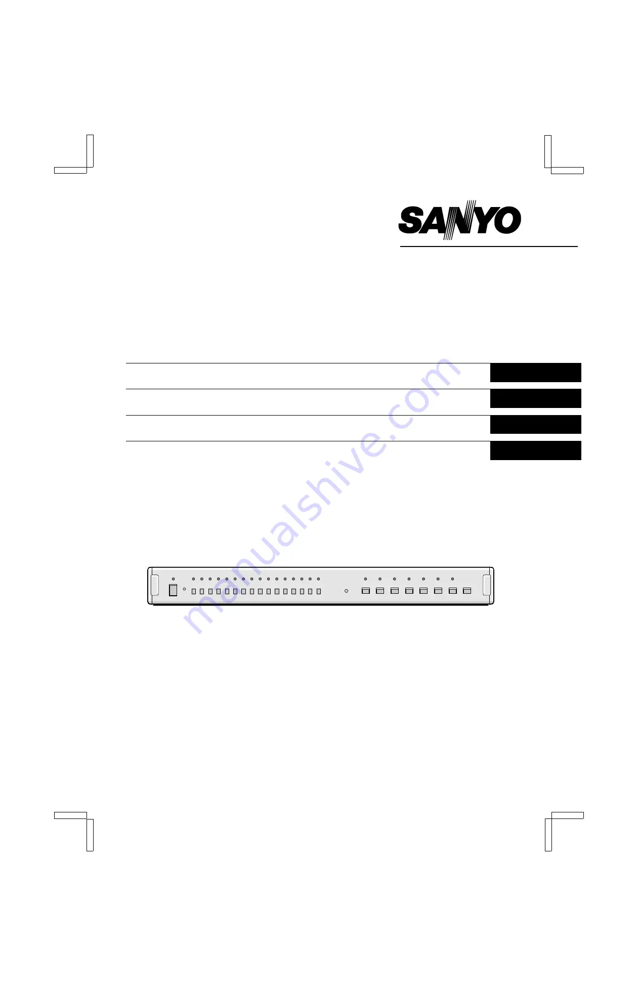
background image

INSTRUCTION MANUAL

MPX-CD16P
MPX-MD16P

Multiplexer

English

GB 

Multiplexer

Deutsch

Multiplexeur

Français

Multi distributore

Italiano


About this manual

•  Before installing and using the camera, please read this manual 

carefully. Be sure to keep it handy for later reference.

•  This manual gives basic connections and operating instructions for 

2 models (Colour MPX-CD16P, B/W MPX-MD16P).

Über diese Bedienungsanleitung

•  Lesen Sie bitte vor der Montage und dem Inbetriebnehmen der 

Kamera zuerst diese Bedienungsanleitung sorgfältig durch und 
bewahren Sie sie zum späteren Nachschlagen auf.

•  In dieser Anleitung finden Sie die Anschlüsse und die 

Grundbedienung für 2 Modelle (Farbe: MPX-CD16P, Schwarzweiß: 
MPX-MD16P).

À propos de ce manuel

•  Avant d'installer et d'utiliser la caméra, veuillez lire ce manuel 

attentivement. Gardez-le à portée de main pour toute référence 
ultérieure.

•  Ce manuel couvre les branchements et instructions pour l’utilisation 

de base pour 2 modèles (Couleur: MPX-CD16P, noir et blanc: 
MPX-MD16P).

Nota su questo manuale

•  Prima di procedere all’installazione ed all’uso dell’apparecchio, 

leggere attentamente questo manuale di istruzioni, e conservarlo 
per ogni eventuale futura consultazione.

•  Il manuale contiene le istruzioni per i collegamenti ed il 

funzionamento di due tipi di modelli, l’MPX-CD16P (a colori) e 
l’MPX-MD16P (in bianco e nero).

L8FA5/XE (MPX-CD16P, MD16P GB) 1997. 12. 18
 

Summary of Contents for MPX-CD16P

Page 1: ...ser Anleitung finden Sie die Anschlüsse und die Grundbedienung für 2 Modelle Farbe MPX CD16P Schwarzweiß MPX MD16P À propos de ce manuel Avant d installer et d utiliser la caméra veuillez lire ce manuel attentivement Gardez le à portée de main pour toute référence ultérieure Ce manuel couvre les branchements et instructions pour l utilisation de base pour 2 modèles Couleur MPX CD16P noir et blanc ...

Page 2: ...oiding Electrical Shock and Fire Do not handle the power cord with wet hands Do not pull on the power cord when disconnecting it from an AC wall outlet Grasp it by the plug If any liquid is spilled on the Multiplexer unplug the power cord immediately and have the unit inspected at a factory authorised service centre Do not place anything directly on top of this Multiplexer SERVICE This unit is a p...

Page 3: ...K SCREEN DISPLAY CONTROL 20 Split Screen Viewing 21 x2 Zoomed In Image Viewing 21 Freezed Image Viewing 21 Full Screen Image Viewing 22 Full Screen Sequential Viewing 22 VCR Recorded Picture and Camera Live Picture Simultaneous Viewing 23 SPECIFICATIONS 24 FEATURES Settings entered by on screen menus Clock settings Titles Alarms On screen displays Recording mode Alarm data Monitor 1 output screen ...

Page 4: ...set the menus as indicated below 1 Turn the unit off 2 Keep the MENU button pressed down then press the ON button Reset the menus only if it is absolutely necessary Resetting the menus will erase the settings previously entered and will also affect the internal clock Button Lock Function This unit is equipped with a function that lets you lock the buttons to prevent any undesired operation during ...

Page 5: ...r input NOTE Model MPX MD16P does not have S VIDEO IN OUT terminals Control terminal No Signal No Signal 1 Alarm input 1 14 Alarm input 14 2 Alarm input 2 15 Alarm input 15 3 Alarm input 3 16 Alarm input 16 4 Alarm input 4 17 GND 5 Alarm input 5 18 No operation 6 Alarm input 6 19 No operation 7 Alarm input 7 20 No operation 8 Alarm input 8 21 GND 9 Alarm input 9 22 No operation 10 Alarm input 10 2...

Page 6: ... 360 Ω SW20 MULTI 470 Ω SW21 PLUS 1 680 Ω SW22 SEQUENCE 820 Ω SW23 ZOOM 1 2 kΩ SW24 STILL 1 8 kΩ SW25 POWER To pin 21 Remote controller circuit To pin 23 To pin 17 Alarm sensor door bell interphone etc To pin 15 To pin 16 To pin 14 To pin 13 To pin 12 To pin 11 To pin 10 To pin 9 To pin 8 To pin 7 To pin 6 To pin 5 To pin 4 To pin 3 To pin 2 To pin 1 S VIDEO Before making any connection make sure ...

Page 7: ...te C in the cover B slot Check that the shielding tape is within about 2 3 mm from the end of the cover B Push in the cover B tabs 2 Align the cover D slot with the plug plate C and push down until the clasps E interlock Tighten securely the cover nut A on the covers threads 3 Insert the locking screws F in the holes then fix them by inserting the E ring G between the cover D and the plug plate Be...

Page 8: ...umbers letters symbols To switch selectable settings Button O To move down Button To move the right Monitor 1 screen Menu screen If a camera is not connected to a camera input terminal the message NO VIDEO will appear CLOCK SET menu TITLE SET menu ALARM SET menu DISPLAY SET menu VCR recording SET menu ALARM DATA screen Title input screen Clock display location selection screen NOTES When displayin...

Page 9: ...me broadcast signal or other accurate time signal then press the O button The seconds will start counting from 00 3 Press the or button to set the SUMMER TIME to STANDARD or SUMMER then press the O button 4 Press the MENU button then press the O button to select 7 ENTER and press the MENU button again Concerning the Clock Display The clock is displayed as indicated below For more information on ho...

Page 10: ... then press the button Following the same procedure set the title GATE 5F then press the m button 4 Press the MENU button then press the O button to select 7 ENTER and press the MENU button again Concerning the Title Display The title is displayed as indicated below For more information on how to display the title please refer to CLOCK TITLE DISPLAY on page 11 Split screen 16 divisions Split scree...

Page 11: ...NITOR1 ZOOM ON When an alarm trigger is received the image displayed on monitor 1 will be zoomed in If the alarm trigger was recorded on tape the zoom function will not operate OFF The zoom function will not operate MONITOR1 STILL ON When an alarm trigger is received the image displayed on monitor 1 will be freezed If the alarm trigger was recorded on tape the still function will not operate OFF T...

Page 12: ...displayed To set the clock please refer to CLOCK SETUP OFF The clock is not displayed when the signals from a camera are displayed LIVE TITLE ON The title is displayed when the signals from a camera are displayed To set a title please refer to TITLE SETUP OFF The title is not displayed when the signals from a camera are displayed VCR PB CLOCK ON The clock is displayed when the signals from the VCR...

Page 13: ...EC SPEED Set the duration according to the VCR recording speed SP 3H 12H 24H 48H 72H 96H 120H 168H 240H 360H 480H 720H 960H LP 6H 18H 30H 48H 72H 96H 120H 168H 240H 360H 480H 720H 960H The duration indicated is for when using an E 180 tape Real time VCRs use E 240 tapes therefore the durations will be as indicated by the examples below Set duration based on a E 180 tape 6H 18H 30H Real time VCR re...

Page 14: ...Press the MENU button then press the O button to select 6 ALARM DATA 2 Press the MENU button 3 Press the m button to display the following pages 4 Press the MENU button then press the O button to select 7 ENTER and press the MENU button again NOTE The illustrated alarm data menus show examples of alarm triggers inputs 1 2 3 4 L8FA5 XE MPX CD16P MD16P GB 1997 12 18 English 13 ...

Page 15: ... from camera 1 will be displayed full screen on monitor 2 Monitor 2 b For split screen viewing Monitor 1 b For zoomed in viewing b Freezed frame viewing b For simultaneous camera live and VCR playback viewing VCR playback image Monitor 2 b For full screen viewing b For full screen sequential viewing x2 zoom Freeze frame b For 4 split screen sequential viewing L8FA5 XE MPX CD16P MD16P GB 1997 12 18...

Page 16: ... SELECT 14 button for about 3 seconds The zoomed image will be displayed full screen and SET will be displayed Using the following buttons adjust the zoomed in image position Button O To lower the image Button To move the image towards the right NOTES About 10 seconds after having set the image position the display will automatically return to the original split display The zoomed in image positio...

Page 17: ... the ZOOM button 2 Freezed Image Viewing Press the STILL button You can then view a freezed image and S will flash instead of the camera number While the image is freezed the STILL indicator will flash To return to normal viewing mode press the STILL button again Full Screen Sequential Viewing From the full screen display press the SEQUENCE button to display the images full screen switching sequen...

Page 18: ...d All the camera indicators will go off 2 Selective viewing of the VCR playback Example Camera 5 Press a camera SELECT 5 button The recording from that camera 5 will be played back according to the VCR recording speed The title entered for the camera see TITLE SETUP on page 9 will flash Press the camera SELECT button 5 one more time to return to the previous display mode NOTE If a title has not be...

Page 19: ...ected Monitor 2 Display Setup Press the camera SELECT button corresponding to the desired camera The same image as viewed on monitor 1 will be viewed on monitor 2 This completes the setup 1 Sequential Full Screen Display Press the SEQUENCE button to start sequential display on monitor 1 and monitor 2 The sequence timing is set in menu 4 DISPLAY SET for more information please refer to page 11 2 To...

Page 20: ...ressed like pressing the SELECT button to switch from split screen to full screen display during the alarm operations NOTE The alarm operations cannot be cancelled Please wait until the alarm operation is finished Setup Example The buzzer will ring for about 30 seconds and the image of the corresponding camera will be zoomed in and freezed The ZOOM STILL and corresponding camera indicators will fl...

Page 21: ... time lapse recording in 12 or 24H mode will cause video interference If playing back a tape not recorded through this unit the VCR indicator will flash and the message NO ID will be displayed on screen If a camera picture is not recorded the message NO VIDEO will be displayed on screen We recommend to use the 8 hour mode playback Depending on the real time video recorder model there may be a slig...

Page 22: ...ess the camera SELECT 14 button for about 3 seconds The zoomed image will be displayed full screen and SET will be displayed Using the following buttons adjust the zoomed in image position Button O To lower the image Button To move the image towards the right NOTES About 10 seconds after having set the image position the display will automatically return to the original split display The zoomed in...

Page 23: ...l viewing mode press the ZOOM button 2 Freezed Image Viewing Press the STILL button You can then view a freezed image and S will flash instead of the camera number While the image is freezed the STILL indicator will flash To return to normal viewing mode press the STILL button again Full Screen Sequential Viewing From the full screen display press the SEQUENCE button to display the images full scr...

Page 24: ...will be displayed sequentially The camera indicators will light according to the image displayed on screen 2 Selective viewing of the Camera live pictures Example Camera 5 Press the camera SELECT 5 button The live pictures from camera 5 can be viewed The title entered for the camera see TITLE SETUP will flash NOTE If a title has not been set for that camera the camera number will flash 3 Camera li...

Page 25: ...p by way of menu Alarm output terminal 16 channels output 1 channel Switch input terminal 100 kΩ pull up Control terminal D sub alarm input R C remote control input Pin Alarm output switch input A D 8 bits 256 gradation excluding the sync signal sampling rate 4 x sub carrier frequencies Memory Frame memory Y signal 720 bit C signal 360 bit Skip Automatic VCR OUT terminal MONITOR 1 2 output termina...

Page 26: ...SANYO Electric Co Ltd 1AC6P1P1296 L8FA5 XE L8FB5 XE A 1196KP SY01 Printed in Japan L8FA5 XE MPX CD16P MD16P GB 1997 12 18 ...

Reviews: