background image

Service Manual

Multi-gas Incubator

SANYO Electric Co., Ltd.
Biomedical Business Division 

MCO-19M
MCO-19M(UV)

SM9910245

  FILE No.

(

)

(

)

Summary of Contents for MCO-19M

Page 1: ...Service Manual Multi gas Incubator SANYO Electric Co Ltd Biomedical Business Division MCO 19M MCO 19M UV SM9910245 FILE No ...

Page 2: ...odels This service manual is effective for following models Name Product code Voltage and Frequency MCO 19M 823 633 51 115V 60Hz 823 633 54 230 240V 50Hz MCO 19M UV 823 633 71 115V 60Hz 823 633 74 230 240V 50Hz 㻌 ...

Page 3: ...sensor 75 Parts layout 76 Setting procedures for optional components 77 How to install UV lamp add on kit 䠄MCO 19UVS䠅 81 Installation of H2O2 Generator MCO HP 87 How to install H2O2 decontamination kit MCO HL and Electric lock 88 How to install Roller Base 䠄MCO 18RB䠅 92 How to install Automatic CO2 cylinder changeover䠄MCO 21GC䠅 93 How to install Automatic CO2 density calibration add on kit 䠄MCO SG...

Page 4: ...al evaporation with humidifying pan Temperature controller PID control system Temperature display Digital display䠄Resolution 0 1 o C䠅 CO2 controller PID control system CO2 density display Digital display Resolution 0 1 䠅 O2 controller PID control system O2 density display Digital display Resolution 0 1 䠅 Air circulation Fan assisted Air filter 0 3μm Efficiency 99 97 or more UV lamp Option 4 W 1 Oz...

Page 5: ...Decontamination kit䠄MCO HL䠅 H2O2 Decontamination Reagent 䠄MCO H2O2䠅 Automatic CO2 density Calibration Add on Kit䠄MCO SG䠅 Gas pressure regulator 䠄MCO 100L䠅 Extra tray䠄MCO 47ST䠅including 2 tray supports Half tray䠄MCO 25ST䠅 Automatic CO2 cylinder changeover system䠄MCO 21GC䠅 Roller base䠄MCO 18RB䠅 UV lamp replacement kit MCO 20UV Stacking spacer MCO 18SB when stacking on the MCO 175 Stacking spacer MCO...

Page 6: ...ates DC30V 2A 㻌 with buzzer sounds ŶPerformance specifications Model MCO 19M MCO 19M UV Temperature control range Ambient temp 5䡚50 o C䠄ambient temp 5䡚35 o C䠅 Temperature distribution 0 25 o C䠄ambient temp 25 o C䚸setting 37 o C CO2 5 O2 5 no load䠅 Temperature variation 0 1 o C䠄ambient temp 25 o C䚸setting 37 o C CO2 5 O2 5 no load䠅 CO2 control range 0䡚20 CO2 variation 0 15 䠄ambient temp 25 o C sett...

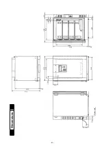
Page 7: ... 4 Dimensions Power cord ...

Page 8: ... 5 CO2 sensor 䚷CO2 inlet 䚷 port N2 O2 inlet port O2 N2 valve A O2 N2 valve B Filter Sample port Front O2 sensor CO2 valve Gas circuits ...

Page 9: ...Select Temp CO2 Calibration 3 Temp CO2 Calibration is displayed and press MENU key to activate MENU key Select OK and press ENTER key OK 4 Change the value in the column Temp Span to 36 5䉝 by pressing digit shift key and numerical value shift key 5 Press MENU key to call MENU screen Select OK and press ENTER key OK 6 Automatically reverts to Select Tools㻌 1 2 screen Note 1 It is important to have ...

Page 10: ...n and press OK key OK 4 By pressing digit shift key and numerical value shift key input actual CO2 density 䠄4 5 䠅 in the column CO2 Span Select OK and press ENTER key OK 5 Automatically reverts to Select Tools 1 2 screen Note㻌 1 Input range 1 0 1 0 per input 2 Repeat CO2 calibration for several times until displayed CO2 density will match with actual density 3 It is permitted to commence CO2 span ...

Page 11: ... OK 5 Automatically reverts to Select Tools 1 2 screen Note 1 㻌 Input range 1 0 1 0 per input 2 㻌 Repeat O2 calibration for several times until displayed CO2 density will match with actual density 3 㻌 It is unacceptable to commence O2 span calibration when setting O2 density deviates㻌 䡂rom 18 0 22 0䠂 㻌 㻌 㻌 There is a blank in the rignt side of 䇾O2 Span䇿 column 䠘Display of Process 2䠚 䠘Display of Pr...

Page 12: ...ensor reference cell voltage䠄CO2 Zero䠅 to 4 00V 0 03V 3 Turn the VR2 around CN3 on the main PCB or measure the voltages both ends of R40 to make CO2 sensor gas cell voltage䠄CO2 Span䠅 to 4 00V 0 03V 4 Input 0 0 by pressing digit shift key and numerical value shift key and 0 1 besides right to the CO2 Zero being turned to black See the picture below 5 Press MENU to call MENU display Select OK and pr...

Page 13: ...alve Option CN21 Control PCB KEY Display PCB LCD CN6 1 2 Door Switch 3 6 MCO HP Option 7 8 Standard gas SW Option CN17 1 2 O 2 A valve 3 4 O 2 B valve CN9 1 2 CO 2 valve 3 4 CO 2 auto changer valve option CN3 3 7 CO 2 sensor CN1 1 5 Power transformer CN2 1 2 Switching power supply CN15 1 3 Water sensor CN16 1 4 O 2 sensor CN10 1 2 Remote alarm output CN11 MTR 480C Option MTR L03 MTR 420MA CN4 1 2 ...

Page 14: ... between 1 and 2 in normal condition CN11 MTR 480 Option Communication board CN12 3 4 Hinge sub heater Control of hinge sub heater CN13 1 2 Buzzer PCB CN14 2 UV lamp ballast 䠄Option for MCO 19M䠅 CN15 1 3 Water sensor Detection of water level in humidifying pan CN16 O2 sensor Control of O2 density CN17 1 2 O2 A valve 3 4 O2 B valve Control of O2 valve CN20 1 2 H2O2 relay 䠄DC24V䠅䠄Option䠅 3 4 Electri...

Page 15: ...ey Type LE 36 LE 36 Resistance 353 7ȍ 1460ȍ MCO HL option Rating DC24V DC24V Bottom side heater R L Rating AC115V 14W AC230V 14W Standard gas switch Type SPS 35 SPS 35 Resistance 945ȍ 5290ȍ MCO SG option Rating 5KPA 5KPA Side heater R L Rating AC115V 30W AC230V 30W Standard gas valve Type FAB11 X2265 FAB11 X2265 Resistance 441ȍ 1763ȍ MCO SG option Rating DC24V DC24V Top heater Rating AC115V 8 0W A...

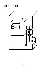
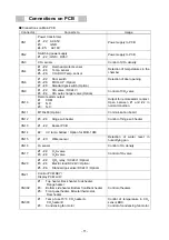
Page 16: ...Wiring diagram 13 ...

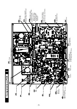
Page 17: ...Circuit diagram Main PCB 14 ...

Page 18: ... LCD PCB 15 ...

Page 19: ...opScreen press MENU key and select Set to display Stand by Setting screen Move a curser on CO2 Density and set a value by pressing numeric keys Press MENU key and select OK and press ENTER key to memorize the value 3 N2 O2 control 1 Setting range 1 0 80 0 Default setting 20 0 It is uncontrolled O2 density when O2 setting range is exceeding 18 0 and less than 22 0 2 Automatic set O2 density alarm H...

Page 20: ...rm will be active 4 Automatic set O2 density alarm Setting range Set O2 density 0 5 5 0 Default setting 1 0 When a O2 density deviates from alarm setting range the digits displaying current O2 density will start blinking The following message will be displayed after an alarm delay time 0 30minutes elapses Waring High O2 Density For high O2 density alarm Warning Low O2 Density For low O2 density al...

Page 21: ...yed Err03 CO2 Gas Connect Abnormal Buzzer will sound intermittently and remote alarm will be active 11 Err04 It is wrong N2 O2 gas connection If a chamber O2 density is changed wrongly when a N2 O2 valve is opened the following message will be displayed Err04 N2 O2 Gas Connect Abnormal Buzzer will sound intermittently and remote alarm will be active 12 Err05 Err06 Temp sensor is abnormal When a te...

Page 22: ...e displayed Err15 Door heater Abnormal Buzzer will sound intermittently and remote alarm will be active 19 Err16 CO2 sensor Box heater is abnormal When a CO2 sensor Box heater is disconnected or CO2 sensor Box heater SSR is short circuited the following message will be displayed Err16 CO2S Box Heater Abnormal Buzzer will sound intermittently and remote alarm will be active 20 Err 17 SSR for main h...

Page 23: ...er door is left opened before starting H2O2 decontamination Err33 Door is Opening will be displayed 26 Err34 Err35 Err36 Err37 Failure during H2O2 decontamination a When it is not detected completion of H2O2 generating if the setting time is extended Err34 H2O2 Volume will be displayed b When a power is interrupted during H2O2 decontamination Err35 Power Failed will be displayed after the unit ret...

Page 24: ...r08 CO2S Box Temp Sensor Short Ambient temp sensor on PCB is disconnected Err09 AT Sensor Open Ambient temp sensor on PCB is short circuited Err10 AT Sensor Short CO2 sensor Vref voltage is abnormal Err11 CO2 Sensor Vref Abnormal CO2 sensor Vgas voltage is abnormal Err12 CO2 Sensor Vgas Abnormal Main heater is disconnected SSR is short circuited Err13 Main Heater Abnormal Bottom heater is disconne...

Page 25: ...oes not sound again and remote alarm is not active again 8 Alarm delay time Alarming condition is noticed by sounding buzzer and activating remote alarm after predetermined delay time elapses Setting range 1 CO2 density alarm 1 15 minutes Default setting 15 minutes 0 minute Not delayed 2 O2 density alarm 1 30 minutes Default setting 30 minutes Note O2 density alarm will emit after twice of setting...

Page 26: ...oor open high low temperature alarm high low CO2 density alarm and high low O2 density alarm When an apparatus is in normal condition OK is displayed z CO2 Auto changer display A or B in the right side of setting CO2 density is displayed when an optional Automatic CO2 cylinder changeover system MCO 21GC is installed Either A or B displayed in reverse video means that alternative CO2 cylinder betwe...

Page 27: ... O2 density display starts blinking z When high temperature alarm is occurred and alarm delay time is expired Warning High Temp is displayed in the message field z When low temperature alarm is occurred and alarm delay time is expired Warning Low Temp is displayed in the message field z When high CO2 density alarm is occurred and alarm delay time is expired Warning High CO2 Density is displayed in...

Page 28: ...㻌 䣖 䣧 䣯 䣲 䢵 䢹 䢰 䢲 䤑䣅 䣅 䣑 䢴 䢷 䢰 䢲 䢧 䣑 䢴 䢷 䢰 䢲 䢧 䣃 䣄 䣕 䣶 䣣 䣶 䣷 䣵 䣔 䣊 䣒 䣃 䣐 䢷 䢰 䢲 䢷 䢰 䢲 䢵 䢹 䢰 䢲 㻌 㻌 When humidifying water becomes empty RH PAN is displayed in reverse video in the center of Status field When humidifying water is fully filled blank display Status of UV lamp 㻌 䣖 䣧 䣯 䣲 䢵 䢹 䢰 䢲 䤑䣅 䣅 䣑 䢴 䢷 䢰 䢲 䢧 䣑 䢴 䢷 䢰 䢲 䢧 䣃 䣄 䣕 䣶 䣣 䣶 䣷 䣵 䣗 䣘 䢷 䢰 䢲 䢷 䢰 䢲 䢵 䢹 䢰 䢲 㻌 When UV lamp illuminates UV is displaye...

Page 29: ... 䢰 䢹 䢵 䣎 䣱 䣩 䣕 䣧 䣶 䣇 䣐 䣗 䣅 䣑 䢴 䤑䣅 䣖 䣧 䣯 䣑 䢴 䣏 䢷 䢰 䢲 䢧 䣲 䢵 䢹 䢰 䢲 㻌 㻌 㻌 Automatic elimination of MENU key When MENU key is displayed and there is no key operation for 1 minute MENU key is automatically eliminated from the display Renewal of display When MENU key is not displayed the display is renewal once for an hour 㻌 㻌 ...

Page 30: ...Density column In Stand by Setting display Input required value and press MENU key and select OK in reverse video Press ENTER key to memorize the input value Setting range is 0 20 0 Note Maximum 20 0 for settable value Error tone is not emit if you input a value over 20 0 Setting of O2 density In Top Screen press MENU key and select Set Press ENTER key to display current setting O2 density in the ...

Page 31: ...ill be disappeared from the upper right side in Stand by Setting display after the buzzer sounds shortly Press MENU key and select OK and press ENTER key to memorize the setting Note Key Lock status will not be changed if you select Cancel in MENU key When an input value corresponds to password the buzzer sounds shortly and password input display and Key Lock In Stand by Setting display will be di...

Page 32: ...ature 2 5 for CO2 density 10 for O2 density z Every press up shift key 䊺 and down shift key 䊼 it appears temperature display or CO2 density display or O2 density display in turn z Date and time will be oldered by pressing left shift key 䊹 z Date and time will be updated by pressing right shift key 䊻 z Recording time 2 30 minutes Factory default 6 minutes per day z Recording period 2 weeks z Displa...

Page 33: ... 㻼 㻯 㻚 㼍 㼠 㼛 㼛 㼓 㼐 㻿 䣧 㼚 㼐 㼘 䢱 䢳 䢹 䢲 䢱 䢲 䢷 䢴 䢲 䢳 䣆 䣣 䣶 䣣 䣎 䣱 䣩 䣧 䣮 䣅 䣣 䣰 䣥 䣕 䣶 䣣 䣴 䣶 㼍 㼠 䣏 䣇 䣐 䣗 䣵 䣵 䣱 䣩 䣴 䣧 䣒 䣴 㻌 㻌 㻌 㻌 㻼 㻯 㻚 㼠 㼛 㼓 㼐 㼍 㻿 䣧 㼚 㼐 㼘 㼛 䢸 䢴 䢷 䢰 䢰 䢰 䣦 䣫 䣰 䣩 䣕 䣧 䣰 䢳 䢹 䢱 䢲 䢷 䢱 䢴 䢲 䢳 䢲 䣣 䣶 䣣 䣎 䣱 䣩 䣆 䣮 䣣 䣰 䣥 䣧 䣶 䣣 䣴 䣶 䣕 㼍 㼠 䣅 䣇 䣐 䣗 䣏 䣵 䣵 䣱 䣩 䣴 䣧 䣒 䣴 㻌 㻌 㻌 㻌 䢷 䢸 䢴 䣧 䣦 䢰 䢰 䣈 䣫 䣰 䣫 䣵 䣪 䢳 䢹 䢱 䢲 䢷 䢱 䢴 䢲 䢳 䢲 䣣 䣶 䣣 䣱 䣩 䣆 䣎 䣮 䣅 䣣 䣰 䣥 䣧 㻯 㻚 㼠 㼛 㻼 㼍 㼠 㼍 㼛 㼓 㼐 㼚 㼐 㼘 㻿 䣧 䣕 䣶 䣣 䣴 䣶 䣏 䣇 䣐 䣗 䣵 䣵 䣱 䣩 䣴 䣧...

Page 34: ...g left and right shift key 䊹㻌 䊻 Display MENU key and select PC All and press ENTER key to display Progress in the upper left side Select Start in MENU key and press ENTER key to transfer all Log data to PC with displaying Sending and quantity of transferring data in the lower side Finished will be displayed when transferring 1day Log data is complete Note Select Cancel in MENU key and press ENTER ...

Page 35: ...elect Temp CO2 O2 Calibration and press ENTER key to display Temp CO2 O2 Calibration 1 2 Input actual measured value in the right side of Temp Span column 3 Press MENU key and select OK Press ENTER key to start temperature calibration automatically 4 Repeat the calibration until display temperature corresponds to the actual temperature Note䠅 Input range per calibration is within 1 0䉝 against displ...

Page 36: ... Note It is possible to input 0 0 besides CO2 Zero column only when CO2 setting is 0 0 and O2 setting is 18 0 22 0 It is impossible to input a value besides O2 Zero column CO2 and O2 zero calibration are done simultaneously It is impossible to calibrate CO2 or O2 individually When CO2 setting is 0 0 there is a blank besides CO2 Span column When O2 setting is 18 0 22 0 there is a blank besides O2 S...

Page 37: ... to start CO2 calibration automatically 㻌 㻌 㻌 Perform CO2 calibration until display CO2 density corresponds to actual CO2 density Note It is impossible to perform CO2 span calibration when setting CO2 density is 0 0䠂 There is a blank in the right side of CO2 Span column Ex 䠅 When CO2 density setting is 5 0 and actual CO2 density is 4 5 Procedures MENU key 0 Measure CO2 density by sampling port in ...

Page 38: ...start O2 calibration automatically 㻌 㻌 㻌 Perform O2 calibration until display CO2 density corresponds to actual CO2 density Note It is impossible to perform O2 span calibration when setting O2 density deviates from 18 0 22 0 There is a blank in the right side of O2 Span column Ex 䠅 When O2 density setting is 5 0 and actual O2 density is 4 5 Procedures MENU key 0 Measure O2 density by sampling port...

Page 39: ...䢫 䣆 䣱 䣱 䣴 䣆 䣧 䣮 䣣 䣻 䢴 䣯 䣫 䣰 䢪 䢳 䢯 䢵 䢲 䣯 䣫 䣰 䢫 㻌 Setting range of high temperature alarm is 1 0 5 0䉝 䠄Factory default 1 0䉝䠅 Setting range of low temperature alarm is 1 0 5 0䉝 䠄Factory default 1 0䉝䠅 Note When you input a value lower than 1 0 it is memorized as 1 0䉝 When you input a value over than 5 0 it is memorized as 5 0䉝 Setting range of high CO2 density alarm is 0 5 5 0 䠄Factory default 1 0 䠅 S...

Page 40: ...f you input a value more than 15 minutes alarm delay time will be set in 15 minutes Ring Back time Setting range is 1 99 minutes Factory default 30 minutes Door open alarm delay time When an outer door leaves open an audible alarm sounds after predetermined time elapsed Setting range of door open alarm delay time is 1 30 minutes Factory default 2 minutes Note When you input 0 minute door open alar...

Page 41: ...communication speed is automatically set in 9600bps DAQ communication ID DAQ communication ID number is settable only when an optional MTR 480 is installed Settable range is 0 250 Factory default 0 When you input 0 in the right side of DAQ ID DAQ is not communicable Note When you input a value over than 250 DAQ communication ID number is set in 250 㻌 䣑 䣍 䣷 䣵 䣕 䣶 䣣 䣶 䣖 䣱 䣱 䣮 䣵 䣎 䣱 䣩 䣕 䣧 䣶 䢷 䢰 䢲 䢲 䢵...

Page 42: ...les apparatus to control in remote Note When you input a value which is over than 2 DAQ communication mode is automatically sent in 0 Local Remote alarm contact When you input 0 in the right side of Remote Alarm activity in remote alarm contact will correspond to buzzer during alarm condition When you input 1 in the right side of Remote Alarm activity in remote alarm contact will not correspond to...

Page 43: ...Settable range of UV lamp illumination time is 0 30 minutes Factory default 0 minute 㻌 Note When you input a value over than 30 UV lamp illumination time is automatically set in 30 minutes If an apparatus is not set in UV lamp optional setting 1 is not selected in UV Function column in the System Configuration display UV Setting is not appeared and it automatically returns to Top Screen If an appr...

Page 44: ...de column in UV Setting display UV lamp 24hours illumination mode is inactive When you input 1 in the right side of UV 24h Mode column in UV Setting display UV lamp 24hours illumination mode is active Note If you open an door during UV lamp 24hours illumination mode UV lamp 24hours illumination mode will be forcibly inactive on the way The detection for UV lamp malfunction will not be done during ...

Page 45: ... 䣧 䣶 䣶 䣆 䣃 䣓 䣎 䣅 䣆 䢱 䣕 䣸 䣥 䣫 䣰 䣩 䣕 䣧 䣶 䣶 䣣 䣴 䣯 䣑 䣃 䣮 䣍 䣰 䣣 䣶 䣫 䣱 䣮 䣫 䣤 䣴 䢴 䣅 䣣 䣑 䢴 䢱 䣑 䣯 䣲 䢱 䣅 䣖 䣧 䣗 䣏 䣇 䣐 䢫 䢪 䢳 䢱 䢴 䣱 䣮 䣵 䣶 䣖 䣱 䣧 䣮 䣧 䣥 䣕 㻌 㻌 㻌 㻌 䣍 䣧 䣻 䣎 䣱 䣥 䣭 䣒 䣙 䣕 䣧 䣶 䣶 䣫 䣰 䣩 䣅 䣷 䣴 䣴 䣧 䣰 䣶 䣗 䣵 䣧 䣴 䣒 䣣 䣵 䣵 䣹 䣱 䣴 䣦 䢬 䢬 䢬 䢬 㻌 㻌 㻌 㻌 䣍 䣧 䣻 䣎 䣱 䣥 䣭 䣒 䣙 䣕 䣧 䣶 䣶 䣫 䣰 䣩 䣐 䣧 䣹 䣗 䣵 䣧 䣴 䣒 䣣 䣵 䣵 䣹 䣱 䣴 䣦 䢬 䢬 䢬 䢬 㻌 㻌 㻌 㻌 䣍 䣧 䣻 䣎 䣱 䣥 䣭 䣒 䣙 䣕 䣧 䣶 䣶 䣫 䣰 䣩 䣐 䣧 䣹 䣗 䣵 䣧 䣴 䣒 䣣 䣵 䣵 䣹 䣱 䣴 䣦 䢬 䢬 䢬 䢬 䣔 䣧 䣇 䣰 䣶 䣧 䣴 䣗 䣵 䣧...

Page 46: ...for twice The password for factory default setting is 0000 Note When you input a wrong password audible alarm will sound for 1 5 seconds and Wrong Password will be displayed under Current User Password column It is impossible to change Key Lock password during Key Lock is active Key Lock will be appeared in the upper right side of the display ...

Page 47: ... MENU key and select Tools Tools 1 Press ENTER key and select Date Time in the Select Tools 1 2 display 2 Press MENU key and select OK OK 3 Press ENTER key and input 100517 in the right side of Date column in the Date Time display 4 Press ENTER key and input 184538 in the right side of Time column 5 Press MENU key and select OK OK 6 Press ENTER key and Select Tools 1 2 display is appeared Setting ...

Page 48: ...䣴 䢴 䣅 䣣 䣑 䢴 䢱 䣑 䣯 䣲 䢱 䣅 䣖 䣧 䣗 䣏 䣇 䣐 䢫 䢪 䢳 䢱 䢴 䣱 䣮 䣵 䣶 䣖 䣱 䣧 䣮 䣧 䣥 䣕 㻌 㻌 㻌 㻌 䣮 䣅 䣣 䣰 䣥 䣧 䣕 䣸 䣥 䣰 䣣 䣶 䣫 䣱 䣮 䣫 䣤 䣴 䣵 䣅 䣣 䣵 䣉 䣣 䣰 䣦 䣣 䣴 䣕 䣶 䣣 䣑 䣍 䣫 䣰 䣩 䣕 䣴 䣶 䣶 䣉 䣣 䣵 䣣 䣴 䣦 䣕 䣶 䣣 䣰 䣦 䣇 䣐 䣗 䣏 䢱 䢴 䢫 䣵 䢪 䢴 䣖 䣱 䣱 䣮 䣧 䣥 䣶 䣕 䣧 䣮 㻌 㻌 㻌 㻌 䣕 䣶 䣣 䣰 䣦 䣣 䣴 䣦 䣉 䣣 䣵 䣕 䣧 䣶 䣶 䣫 䣰 䣩 䣕 䣶 䣦 䣉 䣣 䣵 䣅 䣑 䢴 䣆 䣧 䣰 䣵 䣫 䣶 䣻 䢷 䢰 䢲 䢧 䢪 䢶 䢰 䢲 䢧 䢯 䢴 䢳 䢰 䢲 䢧 䢫 䢪 䣐 䣱 䣅 䣣 䣮 䣫 䣤 䣴 䣣 䣶 䣫 䣱 䣰 䢼 䢲 䢰 䢲 䢧 䢫 䣕 䣶 䣦 䣉 䣣 䣵 䣑 䢴 䣆 䣧 䣰 䣵 䣫 䣶 䣻 䢷 䢰 ...

Page 49: ...dard gas will not be calibrated Note When you input a value lower than 0 5 O2 density for standard gas calibration is automatically set in 0 5 When you input a value higher than 81 0 O2 density for standard gas calibration is automatically set in 81 0 Ex When both CO2 and O2 are set in 5 in standard gas calibration Procedures MENU key 0 In Top Screen press MENU key and select Tools Tools 1 Press E...

Page 50: ...tion is displayed 䐡 Error message Error message is displayed 䐢 Message for operator When standard gas calibration mode is complete the message is shown for an operator 䐣 Density in CO2 sensor during standard gas calibration CO2 density sensed by CO2 sensor during standard gas calibration is displayed 䐤 Setting density of CO2 standard gas CO2 density in standard gas cylinder is displayed 䐥 Density ...

Page 51: ... 䣅 䣶 䣫 䣰 䣩 䣕 䣧 䣶 䣮 䣣 䣴 䣯 䣃 䣑 䣍 䣰 䣣 䣶 䣫 䣱 䣮 䣫 䣤 䣴 䢴 䣅 䣣 䣑 䢴 䢱 䣑 䣯 䣲 䢱 䣅 䣖 䣧 䣗 䣏 䣇 䣐 䢫 䢪 䢳 䢱 䢴 䣱 䣮 䣵 䣶 䣖 䣱 䣧 䣮 䣧 䣥 䣕 㻌 㻌 㻌 㻌 䣥 䣧 䣮 䣅 䣣 䣰 䣕 䣸 䣥 䣱 䣰 䣴 䣣 䣶 䣫 䣣 䣮 䣫 䣤 䣣 䣵 䣅 䣴 䣵 䣉 䣣 䣰 䣦 䣣 䣑 䣍 䣕 䣶 䣫 䣰 䣩 䣕 䣴 䣶 䣶 䣉 䣣 䣵 䣣 䣴 䣦 䣶 䣣 䣰 䣦 䣕 䣗 䣏 䣇 䣐 䢫 䢪 䢴 䢱 䢴 䣱 䣮 䣵 䣶 䣖 䣱 䣧 䣮 䣧 䣥 䣕 㻌 㻌 㻌 㻌 䣕 䣶 䣣 䣰 䣦 䣣 䣴 䣦 䣉 䣣 䣵 䣅 䣣 䣮 䣫 䣤 䣴 䣣 䣶 䣫 䣱 䣰 䣕 䣶 䣧 䣲 䢼 䢳 䣕 䣶 䣦 䣉 䣣 䣵 䣅 䣣 䣮 䣫 䣤 䣕 䣻 䣵 䣶 䣧 䣯 䣅 䣪 䣧 䣥 䣭 兟 兟 兟 兟 兟 䣅 䣑 䢴 䢼 䢷 䢰 䢲 䢧 䢮...

Page 52: ... 䣣 䣮 䣫 䣤 䣴 䣣 䣶 䣫 䣱 䣰 䣕 䣶 䣧 䣲 䢼 䢵 䣕 䣶 䣦 䣉 䣣 䣵 䣅 䣣 䣮 䣫 䣤 䣴 䣣 䣶 䣫 䣰 䣩 兟 兟 兟 兟 兟 䣕 䣖 䣉 䢼 䢷 䢰 䢲 䢧 䢮 䣑 䢴 䢼 䢷 䢰 䢲 䢧 䣕 䣖 䣉 䢼 䢷 䢰 䢲 䢧 䢮 䣕 䣖 䣉 䢼 䢷 䢰 䢲 䢧 㻌 㻌 㻌 㻌 䣕 䣶 䣣 䣰 䣦 䣣 䣴 䣦 䣉 䣣 䣵 䣅 䣣 䣮 䣫 䣤 䣴 䣣 䣶 䣫 䣱 䣰 䣕 䣶 䣧 䣲 䢼 䢶 䣕 䣶 䣦 䣉 䣣 䣵 䣅 䣣 䣮 䣫 䣤 䣴 䣣 䣶 䣫 䣰 䣩 兟 兟 兟 兟 兟 䣕 䣖 䣉 䢼 䢷 䢰 䢲 䢧 䢮 䣑 䢴 䢼 䢷 䢰 䢲 䢧 䣕 䣖 䣉 䢼 䢷 䢰 䢲 䢧 䢮 䣕 䣖 䣉 䢼 䢷 䢰 䢲 䢧 㻌 㻌 㻌 㻌 䣖 䣧 䣯 䣲 䢵 䢹 䢰 䢲 䤑䣅 䣅 䣑 䢴 䢷 䢰 䢲 䢧 䣑 䢴 䢷 䢰 䢲 䢧 䣃 䣄 䣕 䣶 䣣 䣶 䣷 䣵 䣑 䣍 䢵 䢹 䢰 䢲 䢷 ...

Page 53: ...2 3 4 5 Status Normal operation Pressure check in standard gas cylinder Stand by for Start key pressed Injecting standard gas CO2 O2 calibration Pressure check for standard gas cylinder Standard gas calibration is complete Standard gas control valve OFF ĺĺĺ ĺĺĺ ON ĺĺĺ OFF Display Std Gas Calib System Check Std Gas Calib Start Std Gas Calibrating Std Gas Calibrating Std Gas Calib Finished Note Err4...

Page 54: ... Tools 1 2 display Cancel When a cylinder becomes empty select OK and press ENTER key to check cylinder and return to Top Screen OK 6 Automatic standard gas calibration is started by pulling gas to both CO2 sensor and O2 sensor 7 When standard gas calibration is complete buzzer beeps with long tone A device automatically returns to Top Screen When a cylinder becomes empty buzzer beeps intermittent...

Page 55: ...㻌 㻌 㻌 䢲 䣃 䢰 䢳 䢰 䢳 䣘 䣧 䣴 䣱 䣣 䣴 䣦 䣆 䣄 䣎 䣅 䣃 䢳 䢰 䢳 䢲 䣘 䣧 䣴 䢰 䣣 䣴 䣦 䣰 䣄 䣱 䣏 䣣 䣫 䢬 䢬 䢬 䣱 䣴 䣦 䣮 䣒 䣣 䣵 䣵 䣹 䣱 䣴 䣦 䣏 䣇 䣐 䣗 䣑 䣍 䣈 䣱 䣴 䣕 䣧 䣴 䣸 䣫 䣥 䣧 䣖 䣱 䣱 䣮 䣵 䣅 䣒 䣣 䣵 䣵 䣹 䣣 䣰 䣥 䣧 㻌 㻌 1 In Top Screen press MENU key and select Tools 2 Press ENTER key to display Select Tools 1 2 and select Svc 3 Press ENTER key to display Password display Input 384 in the right side of Password column 4 Press ENTER key to check...

Page 56: ...n in System Configuration display When you input 0 in the right side of UV Function optional UV lamp function is inactive Factory default When you input 1 in the right side of UV Function optional UV lamp function is active Note When you select 0 UV lamp function is inactive UV Setting display in the Select Tools 1 2 is not appeared and a device automatically returns to Top Screen Note When you in...

Page 57: ...ns that current using cylinder Note When you select 1 optional CO2 autochanger mode is active A or B displayed blinking means that current using cylinder becomes empty Current using cylinder is B when CO2 autochanger mode is active 㻌 䣖 䣧 䣯 䣲 䢵 䢹 䢰 䢲 䤑䣅 䣅 䣑 䢴 䢷 䢰 䢲 䢧 䣃 䣄 䣑 䢴 䢷 䢰 䢲 䢧 䣃 䣄 䣕 䣶 䣣 䣶 䣷 䣵 䣑 䣍 䢷 䢰 䢲 䢵 䢹 䢰 䢲 䢷 䢰 䢲 㻌 㻌 㻌 Setting of Demo mode 㻌 㻌 㻌 㻌 㻌 㻌 This function is used in demonstration...

Page 58: ... 䣥 䣏 䣇 䣐 䣗 䣃 䣰 䣣 䣮 䣱 䣩 䣖 䣧 䣯 䣲 䢳 䢲 䢲 䣑 䣍 䣃 䣰 䣣 䣮 䣱 䣩 䣅 䣑 䢴 䢳 䢲 䢲 䣅 䣣 䣰 䣥 䣧 䣮 䣃 䣰 䣣 䣮 䣱 䣩 䣑 䢴 䢳 䢲 䢲 䣗 䣘 䣎 䣫 䣨 䣧 䢲 䢧 䣏 䣱 䣦 䣧 䣮 䣅 䣱 䣦 䣧 䢲 䣈 䣷 䣰 䣥 䣶 䣫 䣱 䣰 䢲 䢪 䢳 䢲 䢳 䢰 䣒 䣙 䢻 䢴 䢷 䢰 䣋 䣰 䣫 䣶 䢫 㻌 㻌 Reset of UV lamp accumulation time 㻌 When UV lamp is replaced after UV accumulation time reaches 1000hours it is necessary to reset UV lamp accumulation time in non volatile memory 㻌 Reset of UV lamp accumulatio...

Page 59: ... 䣧 䣮 䣣 䣰 䣥 䣴 䣄 䣣 䣧 䣣 䣶 䣧 䣊 㻌 㻌 Adjustment of balance in bottom heater 㻌 Bottom heater output value can be changed for the prevention of chamber condensation or when increasing chamber humidity Setting range is 0 40 Factory default 10 Note When you input a value over 40 bottom heater output value is automatically set in 40 㻌 㻌 㻌 Adjustment of balance in door heater Door heater output value can be c...

Page 60: ...u input a value lower than 1 primary H2O2 misting time is automatically set in 1 minute When you input a value higher than 30 primary H2O2 misting time is automatically set in 30 minutes Note When water sensor signal turns off H2O2 solution s lower than standard during primary H2O2 misting process an apparatus steps to secondary resolution process without commenceing primary H2O2 preservation proc...

Page 61: ...olumn PWM output for CO2 valve A value displayed in the PWM row in the right side of CO2 column Set O2 density A value displayed in the SV row in the right side of O2 column Current O2 density A value displayed in the PV row in the right side of O2 column PWM output for N2 O2 value A value displayed in the PWM row in the right side of O2 column Set temperature in CO2 sensor box A value displayed i...

Page 62: ...10 After commencing initialization a device automatically returns to Top Screen After cancelling initialization a device returns to Select Tools Svc 㻌 㻌 䣣 䣦 䣣 䣶 䣮 䣫 䣼 䣧 䣋 䣰 䣫 䣶 䣫 䣣 䣵 䣶 䣣 䣶 䣷 䣕 䣶 䣫 䣰 䣩 䣕 䣧 䣶 䣧 䣥 䣱 䣰 䣆 䣧 䣮 䣣 䣰 䣥 䣴 䣄 䣣 䣧 䣣 䣶 䣧 䣊 䣥 䣧 䣮 䣅 䣣 䣰 䣥 䣰 䣧 䣶 䣣 䣶 䣫 䣱 䣮 䣫 䣤 䣴 䣩 䣅 䣣 䣰 䣣 䣮 䣱 䣃 䣑 䣍 䣫 䣱 䣰 䣷 䣴 䣣 䣶 䣰 䣨 䣫 䣩 䣯 䣅 䣱 䣻 䣵 䣶 䣧 䣕 䣗 䣏 䣇 䣐 䢲 䣃 䢰 䢳 䢰 䢳 䣘 䣧 䣴 䣕 䣸 䣥 䣱 䣮 䣵 䣶 䣖 䣱 䣧 䣮 䣧 䣥 䣕 㻌 㻌 㻌 䣰 䣫...

Page 63: ...igh low O2 density alarm 1 0 Alarm delay time 15 min Dooer alarm delay time 2 min UV lamp timer 0 min Door heater balance 6 Current conductivity ratio Bottom heater balance 10 Current conductivity ratio Key lock password 0000 CO2 valve control 0 0 CO2 valve A 1 CO2 valve B N2 O2 valve control 0 0 O2 N2 valve A 1 O2 N2 valve B PCB test mode 0 0 OFF 1 ON Demo mode 0 0 OFF 1 ON CO2 Auto changer mode ...

Page 64: ...䢳 䢰 䢲 䢰 䣑 䣈 䢪 䢲 䣱 䣦 䣧 䣆 䣧 䣯 䣱 䣏 䢰 䣑 䣐 䢫 䣈 䣈 䢳 䢪 䢲 䢰 䣑 䢲 䣩 䣧 䣴 䣅 䣪 䣣 䣰 䣷 䣶 䣱 䣣 䣵 䣃 䣑 䢴 䣉 䣅 䣑 䣐 䢫 䣈 䢳 䢰 䢲 䢰 䣑 䣈 䢪 䣱 䣰 䢲 䣰 䣥 䣶 䣫 䣮 䣈 䣷 䣵 䣅 䣣 䣕 䣶 䣦 䣉 䣣 䢰 䣑 䣐 䢫 䣈 䣈 䢳 䢪 䢲 䢰 䣑 䢳 䣰 䣥 䣶 䣫 䣱 䣈 䣷 䣰 䣧 䣥 䣱 䣰 䣆 䣑 䣐 䢫 䣈 䢳 䢰 䢲 䢰 䣑 䣈 䢪 䢳 䣰 䣥 䣶 䣫 䣱 䣗 䣘 䣈 䣷 䣰 䣫 䣱 䣰 䣷 䣴 䣣 䣶 䣰 䣨 䣫 䣩 䣯 䣅 䣱 䣻 䣵 䣶 䣧 䣕 㻌 㻌 㻌 Select System Configuration in Select Tools Svc display Press MENU key and select OK Press ENTER key to display Sy...

Page 65: ...in reverse video H2O2 is preserving H2O2 is not misting 䐢 UV resolution When UV Resolve blinks in reverse video UV resolution is commenced 䐣 Current temperature in H2O2 decontamination 䐤 Door status When an electric lock is active Locked is displayed in the right of Door 䐥 Error message When an error is occurred in H2O2 decontamination an error message is displayed 䐦 Message to operator A message ...

Page 66: ...ect OK OK 8 Press ENTER key to return to Top Screen Step 0 1 2 3 4 5 6 7 8 Status Run in the specificati on Check H2O2 unit Stand by Warming up Primary H2O2 misting Primary H2O2 preservati on Secondary H2O2 misting UV resolution Finish Ultrasonic oscillator OFF ĺ ĺ ĺ ĺ ĺ ĺ ĺ ĺ ĺ ON OFF ON OFF OFF UV Lamp OFF ĺ ĺ ĺ ĺ ĺ ĺ ĺ ĺ ĺ ĺ ĺ ĺ ĺ ĺ ĺ ĺ ĺ ĺ ON OFF Chamber temp 37 0䉝 ĺ ĺ ĺ ĺ ĺ ĺ 37 0䉝 Ļ 45 0䉝 45...

Page 67: ... 䣦 䣻 䣔 䣧 䣥 䣧 䣮 䣅 䣣 䣰 䣑 䣍 䣏 䣇 䣐 䣗 䣫 䣱 䣰 䣫 䣰 䣣 䣶 䣰 䣶 䣣 䣯 䣆 䣧 䣥 䣱 䢴 䣑 䢴 䣊 㻌 㻌 㻌 㻌 䣊 䢴 䣑 䢴 䣆 䣧 䣥 䣱 䣰 䣗 䣘 䣔 䣧 䣵 䣱 䣮 䣸 䣧 䣕 䣶 䣧 䣲 䢼 䢵 䣖 䣧 䣯 䣲 䢼 䢶 䢳 䢰 䢲 䤑䣅 䣙 䣣 䣴 䣯 䣫 䣰 䣩 䣗 䣲 䣆 䣱 䣱 䣴 䢼 䣎 䣱 䣥 䣭 䣧 䣦 䢹 䢻 䢲 䣯 䣫 䣰 䣯 䣯 䣫 䣰 㻌 㻌 㻌 㻌 䣊 䢴 䣑 䢴 䣆 䣧 䣥 䣱 䣰 䣗 䣘 䣔 䣧 䣵 䣱 䣮 䣸 䣧 䣕 䣶 䣧 䣲 䢼 䢶 䣖 䣧 䣯 䣲 䢼 䢶 䢷 䢰 䢲 䤑䣅 䣆 䣱 䣱 䣴 䢼 䣎 䣱 䣥 䣭 䣧 䣦 䣰 䣯 䣯 䣫 䣰 䢸 䢻 䢲 䣯 䣫 㻌 㻌 㻌 㻌 㻌 㻌 ...

Page 68: ... 䣧 䣣 䣵 䣧 䣔 䣧 䣯 䣱 䣸 䣧 䣊 䢴 䣑 䢴 䣗 䣰 䣫 䣶 䣆 䣱 䣱 䣴 䢼 䣗 䣰 䣮 䣱 䣥 䣭 㻌 㻌 㻌 㻌 䣊 䢴 䣑 䢴 䣆 䣧 䣥 䣱 䣰 䣶 䣣 䣯 䣫 䣰 䣣 䣶 䣫 䣱 䣰 䣕 䣶 䣧 䣲 䢼 䢺 㻰 㼑 䣥 䣱 䣰 䣈 䣫 䣰 䣫 㼟 㼔 㼑 㼐 㻚 䣖 䣧 䣯 䣲 䢼 䢶 䢷 䢰 䢲 䤑䣅 䣒 䣗 䣕 䣊 䣏 䣇 䣐 䣗 䣑 䣍 䣆 䣱 䣱 䣴 䢼 䣗 䣰 䣮 䣱 䣥 䣭 㻌 㻌 H2O2 decontamination mode In Top Screen press H2O2 key for 3 seconds to activate H2O2 decontamination mode Note H2O2 decontamination mode will not be active without presetting optional UV ...

Page 69: ...䢴 䣑 䢴 䣆 㻌 㻌 㻌 㻌 䣊 䢴 䣑 䢴 䣆 䣧 䣥 䣱 䣰 䣶 䣣 䣯 䣫 䣰 䣣 䣶 䣫 䣱 䣰 䣕 䣶 䣧 䣲 䢼 䢺 㻴 㻞 䣑 䢴 䣆 䣧 䣥 䣱 䣰 㻭 㼎 㼛 㼞 㼠 㼑 㼐 㻚 䣖 䣧 䣯 䣲 䢼 䢶 䢳 䢰 䢲 䤑䣅 䣒 䣮 䣧 䣣 䣵 䣧 䣔 䣧 䣯 䣱 䣸 䣧 䣊 䢴 䣑 䢴 䣗 䣰 䣫 䣶 䣆 䣱 䣱 䣴 䢼 䣗 䣰 䣮 䣱 䣥 䣭 㻌 㻌 㻌 㻌 㻌 㻌 㻌 㻌 㻌 While the chamber temperature is warming up Step 3 press MENU key to display Abort is active Press ENTER key to display H2O2 Decon Aborted and H2O2 decontamination mode will be forcibly terminated ...

Page 70: ... 䣯 䣲 䣫 䣰 䣯 䣫 䣰 䣯 䢺 䢻 䢲 䣱 䣮 䣸 䣧 䣔 䣧 䣵 䣊 䢴 䣑 䢴 䣆 䣱 䣰 䣧 䣥 䣗 䣘 㻌 㻌 㻌 㻌 䣊 䢴 䣑 䢴 䣆 䣧 䣥 䣱 䣰 䣶 䣣 䣯 䣫 䣰 䣣 䣶 䣫 䣱 䣰 䣕 䣶 䣧 䣲 䢼 䢺 㻴 㻞 䣑 䢴 䣆 䣧 䣥 䣱 䣰 㻭 㼎 㼛 㼞 㼠 㼑 㼐 㻚 䣖 䣧 䣯 䣲 䢼 䢶 䢷 䢰 䢲 䤑䣅 䣒 䣮 䣧 䣣 䣵 䣧 䣔 䣧 䣯 䣱 䣸 䣧 䣊 䢴 䣑 䢴 䣗 䣰 䣫 䣶 䣆 䣱 䣱 䣴 䢼 䣗 䣰 䣮 䣱 䣥 䣭 㻌 㻌 While H2O2 misting Step 4 press MENU key to display Abort is active Press ENTER key to commence UV resolution and to display H2O2 Decon Aborted and H2O2 decontami...

Page 71: ... 䣔 䣧 䣯 䣱 䣸 䣧 䣊 䢴 䣑 䢴 䣗 䣰 䣫 䣶 䣆 䣱 䣱 䣴 䢼 䣗 䣰 䣮 䣱 䣥 䣭 㻌 㻌 㻌 Power failure during H2O2 decontamination mode 㻌 If power fails while H2O2 misting process Step 4 or UV resolution process Step 7 UV resolution will reset and repeat 㻌 If power fails while H2O2 misting process Step 4 Decon Failed will be displayed and Err35 Power Failed will be displayed on the message bar If power fails while UV resolution ...

Page 72: ... time May be caused by faulty oscillator faulty fan poor fan operation or H2O2 generator was set incorrectly Err34 H2O2 Volume Buzzer sounds intermittently Remote alarm activates UV resolution will be commenced Err 35 When power fails during H2O2 is generated Err35 Power Failed is displayed after power returns Decon Failed is displayed after UV resolution process is complete Buzzer sounds intermit...

Page 73: ...䣣 䣴 䣦 䣆 䣄 䣎 䣅 䣃 䢳 䢰 䢳 䢲 䣘 䣧 䣴 䢰 䣣 䣴 䣦 䣰 䣄 䣱 䣏 䣣 䣫 䣦 䣵 䣹 䣱 䣴 䣅 䣒 䣣 䣵 䣣 䣰 䣥 䣧 䣮 䣱 䣮 䣵 䣧 䣖 䣱 䣴 䣸 䣫 䣥 䣴 䣕 䣧 䣑 䣍 䣈 䣱 䣗 䣏 䣇 䣐 䣱 䣴 䣦 䣣 䣵 䣵 䣹 䣒 㻌 㻌 㻌 㻌 㻌 Procedures MENU key 0 In Top Screen press MENU key and select Tools Tools 1 Press ENTER key to display Select Tools 1 2 and press MENU key to select Svc Svc 2 Press ENTER key to display Password and ROM version is displayed 3 Select Cancel in MENU key an...

Page 74: ... sure to wash and sterilize your hands prior to servicing Use 70䠂 ethanol 䐠㻌In installing sterilize the inside wall and shelves after removing shelves duct humidifying pan and so on with 70 ethanol 䠄3䠅㻌In the case that mold has already multiplied Sterilize the interior walls and shelves with 70 ethanol after removed all items from the chamber as same as 2 䐠 above And you should sterilize again aft...

Page 75: ...25 10 00 42 5 44 9 18 70 26 9 63 43 5 26 10 17 96 27 9 28 44 5 08 11 17 24 28 8 94 45 4 91 12 16 55 29 8 62 46 4 75 13 15 90 30 8 31 47 4 59 14 15 28 31 8 02 48 4 44 15 14 68 32 7 73 49 4 30 16 14 12 33 7 46 50 4 16 㻌 CO2 density 䠄䠂䠅 Output voltage 䠄V䠅 CO2 density 䠄䠂䠅 Output voltage 䠄V䠅 CO2 density 䠄䠂䠅 Output voltage 䠄V䠅 0 0 4 00 8 0 3 14 16 0 2 88 1 0 3 82 9 0 3 10 17 0 2 85 2 0 3 63 10 0 3 06 18...

Page 76: ...97 6 411 7 425 9 440 4 40 455 1 470 1 485 4 500 8 516 6 532 7 549 0 565 7 582 6 600 0 50 617 6 635 6 654 0 672 7 691 9 711 5 731 5 752 0 772 9 794 4 60 816 4 839 0 862 1 885 9 910 3 935 4 961 2 987 8 1015 2 1043 5 70 1072 7 1102 9 1134 2 1166 6 1200 2 1235 2 1271 6 1309 5 1349 1 1390 5 80 1434 0 1479 7 1527 9 1578 8 1632 8 1690 3 1751 8 1817 8 1889 2 1966 7 90 2051 6 2145 5 2250 4 2369 4 2506 7 26...

Page 77: ...accuracy can be obtained by comparing both of measured wavelengths constantly in the same temperature condition It is unnecessary to inject ambient air when CO2 zero calibration is commenced with every 4 hours as previous models performed 㻌 㻌 㻌 㻌 Chamber air Infrared ray Contrast wavelength IR sensor Measured wavelength 4 0μm CO2 measured wavelength IR sensor Measured wavelength 4 3μm ...

Page 78: ...he proper location The sensor detects the water level every 30 minutes and just after the outer door is closed It takes several seconds to detect the water level Therefore RH PAN may displayed in reverse video several times in the status display field on LCD panel after the outer door is closed even when the humidifying pan is full CAUTION Foreign particles on the water surface can adhere to the w...

Page 79: ...vered by plate 䛆H2O2 generator 䠄MCO HL 䠄MCO SG 䛇䞉䞉䞉Option Humidifying pan 䛆Sensor BOX䠄Cover is removed䠅䛇 CO2 sensor 䛆Inner bottom䛇 UV lamp 䠄Option for MCO 19M䠅 䛆Electric lock on door Option 䛇 䛆Electric lock on unit Option䠅䛇 O2 sensor Circulating fan motor 䛆Back side䛇 Access hole CO2 valve O2 N2 valve A Humidifying pan Water sensor O2 N2 valve B Remote alarm Main PCB terminal PCB for O2 sensor Glow...

Page 80: ...rd on the screen and error tone emits The password 384 should be input correctly Service code is unchangeable 2 Access to optional components Operation Key Display 1 Service mode Select Tools Svc 2 Select System Configuration and press ENTER key ENTER System configuration window 3 Select applied optional components from System Configuration and input 1 by numeric key Numeric key MENU window 4 Pres...

Page 81: ...UV lamp illuminates for predetermined time after the outer door is closed 3 If UV lamp lighting time is set longer than 5 minutes or if the outer is open and close frequently it may be caused there is condensation in the chamber or temperature distribution is ununiformly or UV lamp lifetime to be shorted by heat emission from the UV lamp 4 Consult a SANYO representative or agent for replacement of...

Page 82: ...nce hold door switch by the tape z Operation check Operation Key Display Remark 1 Top Screen 2 Press H2O2 key for 3 seconds H2O2 H2O2 Decontamination System check starts 3 H2O2 Decontamination screen H2O2 Decon blinks If error message is shown refer to Instruction Manual P 57 4 Ensure if the outer door is locked by electric key 5 Open outer door by using key to check spray performance is correctly...

Page 83: ...Display 1 Top Screen 2 Press MENU key MENU MENU window 3 Select Tool and press ENTER key ENTER Select Tool 4 Select Standard Gas setting on page 2 Press ENTER key ENTER Standard Gas Setting screen 5 Input standard gas density by numeric keys Numeric key 6 Press MENU key MENU MENU window 7 Select OK and press ENTER key ENTER z CO2 and O2 density calibration Operation Key Display Remark 1 Top Screen...

Page 84: ... 㻌 㻌 㻌 㻌 㻌 㻌 㻌 㻌 㻌 Insulation Fig 3 Rear cover Fig 2 4 Take 2 insulations out for the UV lamp lead wire hole as shown in Fig 3 Insulations can be easily taken out by pushing it from inside of the chamber Keep them for reuse 5 Set the UV lamp 䐟 to the hole and make sure to fit correctly Fix the UV lamp cover 䐠 by 2 screws 䐡 Screw Fig 1 Cap 䐟 1 UV lamp 䐠 1 UV lamp cover 䐡 6 Screws 䠄M4䠅 䐣 1 Ballast 䐥...

Page 85: ... 㻌 㻌 㻌 7 Replace the insulations into the UV lamp lead wire hole with the wires passed through the cuts on both insulations See Fig 6 㻌 㻌 㻌 㻌 㻌 㻌 㻌 㻌 㻌 㻌 㻌 㻌 㻌 㻌 㻌 UV lamp lead wire Insulation Fig 6 Fig 5 Humidifying tray cover 8 Remote the 2 caps shown in Fig 7 Fit Glow Ass y 䐢 and Ballast 䐣 by using 4 screws 䐡 䐡Screw 4pcs 䐢Glow Ass y Cap 䐣Ballast Fig 7 ...

Page 86: ...or switch caution label 䐦 UV lamp caution label 䐨 Name plate Put each label on the specified place Use the name plate of MCO 19M UV for MCO 19M Connect them after removing each cover Ballast White 3P Red 2P Blue 2P White 2P White 2P UV lamp White White CN14 white Blue 1P Green 1P Yellow Light blue Noise filter White 9P Power trans Main PCB Glow starter FG 7P Fig 8 䠄For MCO 19AIC 19M䠅 䠄For MCO 18AI...

Page 87: ...0 2 3 4 5 S t a t u s 6 O K 7 㸱㸵 㸮 㸳 㸮 M E N U S e t L o g T o o l s 0 1 0 2 0 3 0 4 0 5 0 6 0 7 0 8 0 9 1 0 1 1 1 2 1 3 1 4 1 5 1 6 1 7 1 8 1 9 2 0 2 1 2 2 2 3 2 4 2 5 2 6 2 7 2 8 2 9 3 0 3 1 3 2 3 3 3 4 3 5 3 6 3 7 3 8 3 9 4 0 P a s s w o r d 䠢 o r S e r v i c e T o o l s P a s s w o r d 㻌 M a i n B o a r d V e r 1 0 0 A L C D B o a r d V e r 1 0 0 a M E N U O K C a n c e l 0 1 0 2 0 3 0 4 0 5 0...

Page 88: ...㸮 M E N U S e t L o g T o o l s 0 1 0 2 0 3 0 4 0 5 0 6 0 7 0 8 0 9 1 0 1 1 1 2 1 3 1 4 1 5 1 6 1 7 1 8 1 9 2 0 2 1 2 2 2 3 2 4 2 5 2 6 2 7 2 8 M E NU O K C a n ce l 2 9 3 0 3 1 3 2 3 3 3 4 3 5 3 6 3 7 3 8 3 9 4 0 1 S e l e c t T o o l s S v c V e r 1 0 0 3 S y s t e m C o n f i g u r a t i o n A n a l o g C a l i b r a t i o n e t c 4 H e a t e r B a l a n c e 5 D e c o n S e t t i n g 㻌 S t a t ...

Page 89: ...because UV lamp would be extended to be lit automatically to compensate for UV output being lower 㻌 12 How to check UV lamp lighting Operation 1 Press door switch with the inner door shut and the outer door opened 2 Several seconds later check if UV indicator on the control panel is lit Check if UV is appeared on LCD screen 3 Check if you can see blue ray at the front of humidifying pan cover You ...

Page 90: ...n the picture and each fixture should be correctly mounted to the holes at the bottom of the duct Err34 The volume of H2O2 generated is abnormal If you find an error message Err34 after predetermined decontamination process is complete the voltage of the apparatus may be out of the specification and it is necessary to adjust H2O2 generating time Please consult to your authorized sales representati...

Page 91: ...over Fit water proof connector to the place as the arrow pointed in the picture Note Mark triangle should be oriented to upper position Fit 2 caps M4 to the holes at cover support Cover support Cap M4 Frame under cover Inner cabinet rear cover Water proof connector Door under cover 䞉㻌 Philips Screwdriver 䞉㻌 Wrench 8mm Connector White 3P Wire Red Wire Brown Screw M4 Rear cover Plate meeting Transfo...

Page 92: ... as arrow pointed in the left picture when you fit electric lock to the unit 䐤 Fit plate meeting to the places as left picture shown and connect each connectors 䠆 Harness for connector Black 3P should be put thorough the tie 㻌 㻌 㻌 Peel seal off from insulation and fit the insulation back to original position Plate meeting Connector Black 3P Tie 㘽 M5 ࣜࢱ ࢺ 㟁Ẽ㘄 ⓑⰍࢥࢿࢡࢱ 2P Connector White 2P Electric l...

Page 93: ...ower is supplied Ensure door opening should be less than 10mm when electric lock is active 䐦 Align the position of electric lock if it is not locked correctly 䐧 Fit the cover back under the frame Door opening should be less than 10mm when electric lock activating Loosen 2 screws to allow electric lock to move toward back Cover ...

Page 94: ... 91 Layout for Name plate and Caution label Put Name plate and Caution label on the following specified places Name plate For MCO 19M UVH Caution label For MCO 19M UVH ...

Page 95: ...As shown in the figure set the unit on the roller base 䐟 so that its leveling legs can fit into the holes 4 holes on the base 2 Insert the fixture 䐠 from the side to the front leveling leg Secure the fixture with 2 screws 䐡 㻌 㻌 㻌 㻌 㻌 㻌 Leveling leg ...

Page 96: ...ollowing procedure is necessary only when mounting to MCO 19AIC or MCO 19M 1 Remove 2 tube bands on the CO2 valve assy Ĭ and then remove the hose and capillary 2 Remove the straight connector from the inlet side of the CO2 valve assy and replace with the straight connector Ķ Make sure it is fixed firmly to prevent gas leakage Parts list ĵ tube L100 Used for MCO 18AIC 18M MCO 19AIC MCO 19M MCO 18AC...

Page 97: ...e B to the connector yellow of wiring harness from CN9 on Main board 6 Disconnect upper tube of CO2 valve A Connect CO2 valve A and CO2 valve B and tube X by using ղ as shown in Fig 3 1㹼3 4 7 Connect bottom tube of ձ to ճ 8 Connect the port with CO2 gas supply line B by using չ 9 Fix tubes securely using ն and շ as shown in Fig 3 1㹼3 4 10 Mount the rear cover back to the place NOTE All the tubes s...

Page 98: ...A Fig 3 4 MCO 18AC CO2 gas supply line A white Main board CN9 CO2 gas supply line B CO2 valve A CO2valve B Tube X Connector yellow cap Fig 3 2 MCO 18AIC MCO 19AIC ĭ Ĭ ij į İ Į Ĵ IJ ı CO2 valve B Tube X Connector yellow Cap CO2 gas supply line A white Main board CN9 CO2 gas supply line B ĭ Ĭ ij į İ Į Ĵ IJ ı Fig 3 3 MCO 18 ȷMCO 19 CO2 valve A ...

Page 99: ...he figure to 384 6 Press ENT key ENT The current chamber temperature is displayed 7 Press CAL key for 5 seconds CAL The left digit in the temperature indicator is flashed 8 By pressing key and key set the figure to F08 9 Press ENT key ENT In CO2 density indicator 0 is displayed and the right digit is flashed 10 By pressing key and key set only the left digit figure to 1 NOTE Do not change center a...

Page 100: ...d buzzer sounds after 2 7minutes later since the CO2 inject lamp lights Check if the cylinder A is switched to the cylinder B For MCO 20AIC MCO 18AIC 18AC check if CO2 gas supply line indicator A starts blinking and the indicator B lights For MCO 18M check if the CO2 gas supply line indicator starts blinking 6 Check if the CO2 density is displayed as 5 and keep it stabilized NOTE When the decimal ...

Page 101: ...2 0 2 1 2 2 2 3 2 4 2 5 2 6 2 7 2 8 2 9 3 0 3 1 3 2 3 3 3 4 3 5 3 6 3 7 3 8 3 9 4 0 P a s s w o r d F o r S e r v i c e T o o l s P a s s w o r d 㻌 M a i n B o a r d V e r 1 0 0 A L C D B o a r d V e r 1 0 0 a M E N U O K C a n c e l 0 1 0 2 0 3 0 4 0 5 0 6 0 7 0 8 0 9 1 0 1 1 1 2 1 3 1 4 1 5 1 6 1 7 1 8 1 9 2 0 2 1 2 2 2 3 2 4 2 5 2 6 2 7 2 8 M E NU O K C a n ce l 2 9 3 0 3 1 3 2 3 3 3 4 3 5 3 6 ...

Page 102: ...9 2 0 2 1 2 2 2 3 2 4 2 5 2 6 2 7 2 8 M E NU O K C a n ce l 2 9 3 0 3 1 3 2 3 3 3 4 3 5 3 6 3 7 3 8 3 9 4 0 1 S e l e c t T o o l s S v c V e r 1 0 0 3 S y s t e m C o n f i g u r a t i o n A n a l o g C a l i b r a t i o n e t c 4 H e a t e r B a l a n c e 5 D e c o n S e t t i n g 㻌 S t a t u s 6 I n i t i a l i z e d a t a M E N U O K C a n c e l 0 1 0 2 0 3 0 4 0 5 0 6 0 7 0 8 0 9 1 0 1 1 1 2 ...

Page 103: ...y be over 1 hour until the indication turns over and the indication of CO2 may not be turned over in case low ambient temperature 5 Check if Error01 CO2 Gas Empty is displayed and buzzer sound after 2 7 minutes elapse since the indication was turned over Ensure indicator of cylinder A should start blinking and indicator of cylinder B turns over 6 Ensure CO2 density indication should be 5 and CO2 s...

Page 104: ...bel between clips 4 Fit the filter Make sure the orientation 5 Fit the plate meeing 6 Apply clips as left picture specified Place the tube as the left picture specified Note䠅 Take care for the tube should not be bent 䐢 Connect each parts with connectors Plate meeting Filter Tube joint Clip Label Tube connect Screw M4 10 Clip Philips screwdriver Monkey wrench Sensor BOX Rear cover 1 Tube joint 4 Fi...

Page 105: ... AT 20䉝䚷SV 37䉝 CO2 setting 5 O2 setting 5 No load Temperature change during power failure 20 25 30 35 40 0 1 2 3 4 Time䠄Hour䠅 Temperature䠄䉝䠅 AT 20䉝䚷SV 37䉝 CO2 setting 5 O2 setting 5 No load Humidity pull up data 0 10 20 30 40 50 60 70 80 90 100 0 1 2 3 4 5 6 Time 䠄Hour䠅 Humidity䠄 䠅 AT 20䉝䚷SV 37䉝 CO2 setting 0 O2 setting 20 No load ...

Page 106: ...ime䠄Minutes䠅 Humidity䠄䉝䠅 30sec door open 60sec door open 30sec door open with N2 bubbling 60sec door open with N2 bubbling CO2 density recover data 㻜 㻝 㻞 㻟 㻠 㻡 㻢 0 10 20 30 40 Time䠄Minutes䠅 CO2 density䠄 䠅 1 small door 60sec open 1 small door 30sec open AT 20䉝䚷SV 37䉝 CO2 setting 5 O2 setting 5 No load AT 20䉝䚷SV 37䉝 CO2 setting 5 O2 setting 5 No load AT 20䉝䚷SV 37䉝 CO2 setting 5 003MPa O2 setting 5 0...

Page 107: ...No load Days before CO2 tank becomes empty 0 100 200 300 400 500 600 700 800 0 1 2 3 4 5 6 7 8 9 10 Door open shut per day Frequency Days AT 20䉝䚷SV 37䉝 CO2 setting 5 Gas leak 4 7 per 30min No load Days before N2 O2 tank becomes empty 0 2 4 6 8 10 12 14 16 18 20 0 1 2 3 4 5 6 7 8 9 10 Door open shut per day Frequency Days AT 20䉝䚷SV 37䉝 CO2 setting 5 O2 setting 5 Gas leak 4 8 per 30min No load ...

Page 108: ...䚷Front 36 96 36 98 36 90 36 89 36 98 37 00 37 02 36 97 36 92 36 91 Data is the reference only Left Right Measuring condition 25䉝 37䉝 0 15 9 10 11 12 7 8 13 14 Measured point Ambient temp Setting temp Setting CO2 1 2 3 4 5 6 H220mm H220mm H105mm H120mm 8 6 9 7 10 3 1 4 2 5 13 11 14 12 15 50mm away from corner Center ...

Page 109: ... page in Service manual but page in the lower corner of each page in the extract from Instruction Manual This page number is not corresponded with serial number in Service manual 䊶㩷 The attached Instruction Manual corresponds to the specifications for initial production so the contents may be changed without notice Instruction manual ...

Page 110: ...MCO 19M UVH MCO 19M UV MCO 19M Multi Gas Incubator INSTRUCTION MANUAL 107 ...

Page 111: ...P 28 Automatic N2 or O2 gas cylinder changeover P 30 Setting the upper limit alarm temperature P 32 ALARM PARAMETERS P 33 UV LAMP PARAMETERS P 34 Using the UV lamp P 34 Precautions when using the UV lamp P 35 Setting the UV lamp ON period P 36 Lighting the UV lamp for 24 hours P 37 OTHER PARAMETERS Setting the date time and log interval P 38 Initial settings LCD DAQ parameters P 40 DISPLAYING THE ...

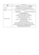
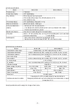
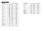
Page 112: ...CONTENTS SPECIFICATIONS P 74 PERFORMANCE P 75 SAFETY CHECK SHEET P 76 109 2 ...

Page 113: ...is manual are subject to change without notice for improvement of performance or functions Ŷ Contact a Sanyo sales representative or agent if any page of the manual is lost or the page order is incorrect Ŷ Contact a Sanyo sales representative or agent if any point in this manual is unclear or if there are any inaccuracies Ŷ No part of this manual may be reproduced in any form without the expressed...

Page 114: ...bol shows this symbol means caution this symbol means an action is prohibited this symbol means an instruction must be followed Be sure to keep this manual in a place accessible to users of this unit Label on the unit This mark is labeled on the cover in which the electrical components of high voltage are enclosed to prevent the electric shock The cover should be removed by a qualified engineer or...

Page 115: ...s not grounded it will be necessary to install a ground by qualified engineers Never ground the unit through a gas pipe water main telephone line or lightning rod Such grounding may cause electric shock in the case of an incomplete circuit Connect the unit to a power source as indicated on the rating label attached to the unit Use of any other voltage or frequency other than that on the rating lab...

Page 116: ... may result in electric shock or fire by short circuit Disconnect the power supply plug before moving the unit Take care not to damage the power cord A damaged cord may cause electric shock or fire Disconnect the power plug when the unit is not used for long periods Keeping the connection may cause electric shock current leakage or fire due to the deterioration of insulation If the unit is to be s...

Page 117: ...etting Be careful not to tip over the unit during movement to prevent damage or injury Prepare a safety check sheet when you request any repair or maintenance for the safety of service personnel Wear rubber gloves when handling the H2O2 reagent Direct contact with the H2O2 reagent may result in inflammation of the skin H2O2 decontamination can be performed only for the chamber and chamber attachme...

Page 118: ... symbol means ON for a power switch This symbol means OFF for a power switch ENVIRONMENTAL CONDITIONS This equipment is designed to be safe at least under the following conditions based on the IEC 61010 1 Ŷ Indoor use Ŷ Altitude up to 2000 m Ŷ Ambient temperature 5o C to 40o C Ŷ Maximum relative humidity 80 for temperature up to 31o C decreasing linearly to 50 relative humidity at 40o C Ŷ Mains su...

Page 119: ...ight Side 21 Rear Left Side For MCO 19M UVH 19M UV or when MCO 19UVS is installed 22 19 20 23 1 2 4 5 6 7 8 9 3 12 13 16 17 inside 15 24 14 10 inside Handles Handles 25 11 For MCO 19M UVH 19M UV or when MCO 19UVS is installed 116 9 ...

Page 120: ... outlet 13 Door switch Detects the door opening closing and stops the circulating fan and electromagnetic valve for CO2 and N2 O2 when door is open UV lamp is also deactivated by door opening 14 Humidifying pan Fill the humidifying pan with sterile distilled water Install the pan properly so that it can be covered with the pan cover 15 Humidifying pan cover The cover prevents UV light entering the...

Page 121: ... cylinder changeover 24 Attachment location for electric key This is the attachment location for the electric key included in the optional Component H2O2 Decontamination Kit MCO HL This kit must be attached to perform H2O2 decontamination Refer to the installation procedure for MCO HL for details 25 Gas injection nozzle MCO 19M UVH 19M UV or when an optional UV System Kit MCO 19UVS is installed 11...

Page 122: ... 6 CE Key Press this key to clear the entered value when entering a setting 7 Cursor Keys Up Down Left and Right Use these keys to move the cursor on the LCD panel 8 ENTER Key Press this key to select a menu command When entering a setting pressing this key to move to the next parameter 9 Numeric Keys 10 H2O2 Key Press this key to start H2O2 decontamination Refer to page 49 for details The followi...

Page 123: ...een COM and N O between COM and N C At normal Open Close At abnormal Close Open Note The alarm is actuated when the power cord is disconnected from the outlet or the power switch is OFF The remote alarm cannot be stopped by pressing the alarm buzzer stop key BUZZER since the remote alarm is not conjunct with the alarm buzzer stop key BUZZER Remote alarm terminal Remote alarm terminal 120 13 ...

Page 124: ...the floor is uneven or the installation is not level the Incubator will be unstable and this may cause accident or injury To avoid vibration and noise always make sure that the installation is stable An unstable surface may result in vibration or noise WARNING Install the Incubator at a location that can support the weight If the floor is not strong enough or if the installation is insufficient th...

Page 125: ...ent electric shock always ground the Incubator If grounding is not possible then have a ground installed by qualified personnel If the Incubator is not grounded it may result in electric shock Never connect the ground wire to a gas pipe water pipe lightning rod or telephone ground wire Doing so may cause electric shock z Installing a ground fault circuit breaker If using the Incubator in a locatio...

Page 126: ... The gas pressure regulator safety valve will operate and there may an explosive sound When the MCO 21GC is not mounted Using the gas supply pipe that is provided connect the CO2 gas pressure regulator for the CO2 gas cylinder to CO2 gas pipe connection port A on the Incubator After connecting the pipe check to make sure that no gas is leaking When the MCO 21GC is mounted Connect a pair of CO2 gas...

Page 127: ...t A B for N2 O2 gas pipe located at the rear left side of the incubator Connect the main cylinder to the connecting port A for N2 O2 gas pipe and connect the sub cylinder to the connecting port B for N2 O2 gas pipe so that the gas supply can be switched automatically when one gas cylinder is empty Connect the same gas type to both connecting port A B for N2 O2 gas pipe Never connect N2 gas and O2 ...

Page 128: ...ps faster recovery of humidity after opening of the inner door Fill the humidifying pan with sterile distilled water so that the injection nozzle can be under the water level Using the inner door and gastight split doors zTo effectively use gastight split doors set three trays standard equipment at the same level as bottom side of each gastight split door At the same level as bottom side of each g...

Page 129: ...ts If water spills from the humidifying pan or if the doors are left open for a long time condensation may form on the inside of the doors If that occurs wipe off the condensation with a dry sterile gauze In particular clean and disinfect the chamber if the culture medium is spilled For details refer to Routine Maintenance on page 45 z Use sterile distilled water in the humidifying pan Always use ...

Page 130: ...e medium incomplete closing or damage to the gasket Before opening the inner door check through the glass to confirm that the UV lamp is OFF if the MCO 19M UVH 19M UV or the optional MCO 19UVS is installed z Be careful when closing the outer door Use the handle when closing the outer door Holding the door in other places may cause injury by getting fingers caught in the door Do not lean on the out...

Page 131: ...O2 gas during decontamination Do not unlock the door during decontamination CORRECT OPERATION Use the following procedure to start trial operation or actual operation of the Incubator 1 Install the Incubator correctly referring to Installation on page 15 2 Remove the packing materials from the chamber and inner attachments Clean and disinfect the chamber and inner attachments referring to Routine ...

Page 132: ...der A and B will be displayed if the optional Automatic CO2 Cylinder Changeover System MCO 21GC is installed The port of the CO2 gas pipe that is currently supplying CO2 will be displayed in reverse video Nothing will be displayed if the MCO 21GC is not installed 6 Display of set value of O2 density The set value of the chamber O2 density is displayed 7 Display of current O2 density The current ch...

Page 133: ...ed When humidifying water is low RH PAN is displayed in reverse video and blinks When the door is open Door Open is displayed in reverse video 10 Message display field A message is displayed when fault occurs The message is displayed alternately in normal characters and reverse video Refer to pages from 55 to 57 for alarm details OK is displayed during normal operation 130 23 ...

Page 134: ...e optional MCO 19UVS page 36 z Setting other parameters The initial settings of the date time and log cycle page 38 and the LCD display and baud rate page 40 can be set z Displaying the operation log and transferring data A graph of past operation data can be displayed page 41 and operation data can be transferred to a PC page 43 z H2O2 decontamination H2O2 decontamination of the chamber and inter...

Page 135: ...nter 050 3 Press the MENU Key to display the menu after setting the parameters Select OK and press the ENTER Key The settings will be saved Note When starting the Incubator for the first time or after not using it for an extended period of time allow at least 4 hours for the chamber temperature humidity CO2 sensor and O2 sensor to become stable after setting the desired chamber temperature at a 0 ...

Page 136: ...ght side of Stand by Setting and changing the temperature and CO2 density settings will be disabled 3 Press the MENU Key to display the menu select OK and press the ENTER Key The settings will be saved 1 S t a n d b y S e t t i n g 2 T e m p e r a t u r e 3 7 0 o C 0 0 o C 5 0 0 o C 3 C O 2 D e n s i t y 5 0 0 0 2 0 0 4 O 2 D e n s i t y 5 0 1 0 1 8 0 5 2 2 0 8 0 0 K e y L o c k 1 0 U n l o c k 1 ...

Page 137: ...ed Enter the correct password The password for releasing the key lock must be shared and administered among all users of the Incubator The password is set to 0000 when the Incubator is shipped from the factory The procedure for changing the password is given next 1 S t a n d b y S e t t i n g K e y L o c k 2 T e m p e r a t u r e 3 7 0 o C 0 0 o C 5 0 0 o C 3 C O 2 D e n s i t y 5 0 0 0 2 0 0 4 O ...

Page 138: ...lect OK and press the ENTER Key The default user password is 0000 when the Incubator is shipped from the factory S e l e c t T o o l s 1 2 T e m p C O 2 C a l i b r a t i o n A l a r m S e t t i n g L C D D A Q S e t t i n g U V S e t t i n g K e y L o c k P W S e t t i n g D a t e T i m e M E N U O K S v C C a n c e l K e y L o c k P W S e t t i n g C u r r e n t U s e r P a s s w o r d 5 1 T e m...

Page 139: ...o display the menu and select Cancel from the menu Note Be careful not to forget the key lock password If you have forgotten the password and cannot release the key lock contact a Sanyo sales representative or agent K e y L o c k P W S e t t i n g N e w U s e r P a s s w o r d R e E n t e r U s e r P a s s w o r d K e y L o c k P W S e t t i n g N e w U s e r P a s s w o r d 136 29 ...

Page 140: ... N2 O2 gas pipe 3 Open the valves of both gas cylinders 4 The current N2 or O2 gas supply line is displayed on the Top Display 5 The incubator detects that there is no more N2 or O2 gas in a cylinder when the O2 density in the chamber does not increase for a while even after opening the N2 O2 gas valve in the Incubator It switches the gas supply line when it detects that there is no more gas At th...

Page 141: ...r restricting of gas tube reduction of N2 or O2 gas pressure or improper opening of N2 or O2 gas cylinder Always check the gas quantity in the cylinder before disconnecting it Ɣ Use the following procedure to manual switch the line between N2 or O2 gas cylinders A and B This procedure shows switching the line from N2 or O2 gas cylinder B to A as an example 1 From the Top Display press the Up Curso...

Page 142: ...C when H2O2 decontamination is performed 2 After setting the parameter press the MENU Key to display the menu select OK and press the ENTER Key The alarm temperature will be saved Refer to the tables of alarms and safety functions for culture operations on page 55 for details Note The alarm temperature will be changed at any time by turning the upper limit regulator even if the Stand by Setting Di...

Page 143: ... alarm delay 1 to 30 minutes Default 2 minutes 0 1 0 2 0 3 0 4 0 5 0 6 0 7 0 8 0 9 1 0 1 1 1 2 1 3 1 4 1 5 1 6 1 7 1 8 1 9 2 0 2 1 2 2 2 3 2 4 2 5 2 6 2 7 2 8 M E NU O K C a n ce l 2 3 0 3 1 3 2 3 3 3 4 3 5 3 6 3 7 3 8 3 9 4 0 S e l e c t T o o l s 1 2 T e m p C O 2 O 2 C a l i b r a t i o n A l a r m S e t t i n g L C D D A Q S e t t i n g U V S e t t i n g K e y L o c k P W S e t t i n g D a t e...

Page 144: ...ter door is closed The default setting is for five minutes z If the outer door is not opened for at least 12 consecutive hours the UV lamp will light for the preset time period every 12 hours z The recommended replacement time for the UV lamp i e when the UV output ratio drops to 60 to 70 of its initial value is when the accumulated ON time reaches 1 000 hours When the accumulated ON time reaches ...

Page 145: ...amp is lit open the outer door and then press the door switch with the inner door still closed Visible blue light can be confirmed from the front of the humidifying pan cover UV light is harmful to the eyes so do not light the UV lamp when the inner door or humidifying pan cover is open z Be careful when handling the UV lamp There is a UV lamp inside of the chamber duct Be careful not to damage it...

Page 146: ...he parameter will be saved 5 1 T e m p 3 7 0 o C C O 2 5 0 O 2 5 0 2 3 4 5 S t a t u s 6 O K 7 37 0 5 0 5 0 M E N U S e t L o g T o o l s 0 1 0 2 0 3 0 4 0 5 0 6 0 7 0 8 0 9 1 0 1 1 1 2 1 3 1 4 1 5 1 6 1 7 1 8 1 9 2 0 2 1 2 2 2 3 2 4 2 5 2 6 2 7 2 8 M E NU O K C a n ce l 9 3 0 3 1 3 2 3 3 3 4 3 5 3 6 3 7 3 8 3 9 4 0 S e l e c t T o o l s 1 2 T e m p C O 2 O 2 C a l i b r a t i o n A l a r m S e t ...

Page 147: ...all attachments from the chamber including the trays tray supports side supports fan cover duct fan humidifying pan humidifying pan cover N2 or O2 gas injection nozzle and Clean all the attachments in an autoclave or with disinfectant alcohol 2 Clean and wipe off inside the chamber with disinfectant alcohol 3 Set the CO2 density to 0 and O2 density to 20 Set the UV 24h Mode to 1 on the UV Setting ...

Page 148: ...lay press the MENU Key to display the menu select OK and press the ENTER Key S e l e c t T o o l s 1 2 T e m p C O 2 C a l i b r a t i o n A l a r m S e t t i n g L C D D A Q S e t t i n g U V S e t t i n g K e y L o c k P W S e t t i n g D a t e T i m e M E N U O K S v c C a n c e l 5 1 T e m p 3 7 0 o C C O 2 5 0 O 2 5 0 2 3 4 5 S t a t u s 6 O K 7 37 0 5 0 5 0 M E N U S e t L o g T o o l s 145 ...

Page 149: ... The default is 6 minutes Ŷ The log interval can be set to between 2 and 30 minutes Ŷ Relation between the log interval and the period that can be saved 1 Log interval of 2 minutes About 5 days 2 Log interval of 6 minutes About 14 days 3 Log interval of 30 minutes About 70 days For the data beyond the above period the older data is deleted to save the newer data 1 D a t e T i m e 3 D a t e 1 0 1 0...

Page 150: ...d DAQ ID and DAQ mode to use the optional communications software Communications software is an optional accessory Contact a Sanyo sales representative or agent for details S e l e c t T o o l s 1 2 T e m p C O 2 C a l i b r a t i o n A l a r m S e t t i n g L C D D A Q S e t t i n g U V S e t t i n g K e y L o c k P W S e t t i n g D a t e T i m e M E N U O K S v c C a n c e l 1 L C D D A Q S e t...

Page 151: ...sities and O2 densities can be displayed on a graph 1 Press the MENU Key from the Top Display to display the menu select Log and press the ENTER Key 1 T e m p 3 7 0 o C C O 2 5 0 O 2 5 0 2 3 4 5 S t a t u s 6 O K 7 5 37 0 5 0 5 0 M E N U S e t L o g T o o l s 148 41 ...

Page 152: ...ft Cursor Key and Right Cursor Key to scroll the displayed data Left Cursor Key older data Right Cursor Key newer data 1 5 0 C 2 0 1 0 1 0 0 1 T e m p 3 4 5 6 0 1 2 2 4 Switched with Up and Down Cursor 1 2 0 2 0 1 0 1 0 0 1 C O 2 3 4 5 6 0 1 2 2 4 Temperature CO2 density Switched with Up and Down Cursor 1 9 0 2 0 1 0 1 0 0 1 O 2 3 4 5 6 0 1 2 2 4 O2 density 149 42 ...

Page 153: ...ows 2000 and Windows XP 1 From the Windows Start Button select Program Accessories Communications HyperTerminal to start the HyperTerminal If the HyperTerminal is not available from the Start Menu execute the following file C Program Files Windows NT hypertrm exe 2 In the HyperTerminal Window set a new connection the name for example Sanyo connection settings method of connection COM1 properties o...

Page 154: ... sensor does not come down completely If necessary set the pan again in the proper location The sensor detects the water level every 30 minutes and just after the outer door is closed It takes several seconds to detect the water level Therefore RH PAN may displayed in reverse video several times in the status display field on LCD panel after the outer door is closed even when the humidifying pan i...

Page 155: ...e to wear gloves may result in cuts or abrasions from sharp edges or corners Note Be careful not to damage the humidifying pan water level sensor or the UV lamp in the chamber duct if the MCO 19M UVH 19M UV or the optional MCO 19UVS is installed Do not use detergents or antiseptic solutions with acid alkali or chlorine Doing so may cause discoloration corrosion or rusting 1 Close the valve of the ...

Page 156: ...from the pins on the rear side See Fig 7 9 Remove the chamber circulation fan by pulling out the central spring and then by pulling out the fan See Fig 8 10 Remove the screw securing the clamp for the side support and remove the clamp See Fig 9 11 Lift the tray brace off of the pins See Fig 10 Fig 4 Fig 5 Fig 6 Fig 7 Fig 8 Fig 9 Fig 10 Humidifying pan Fan cover Duct Fan Clamp Side support Gas inje...

Page 157: ...lcohol When cleaning the sensor take care not to apply excessive force to the lead wires 15 To reinstall all the attachments perform the procedure in reverse order from step 14 Note When installing the fan insert it securely on the motor shaft See Fig 11 Lightly turn the fan manually to make sure that it does not strike the rear panel Improper insertion may cause poor performance As shown in Fig 1...

Page 158: ... See Fig 3 6 Set the pan with the inner side flush against the back and replace the cover Close all gastight split doors inner door and outer door and confirm that RH PAN is not displayed in reverse video in the status display area Note Preheat to 37qC the water to be added to the humidifying pan Adding low temperature water will lower the temperature and humidity in the chamber If the water level...

Page 159: ...perature alarm to 50qC or higher z For the H2O2 reagent use one bottle of the H2O2 Decontamination Reagent specified by Sanyo MCO H202 z After decontamination dilute the residual H2O2 Decontamination Reagent in the H2O2 Generator with a large quantity of water and dispose of it and rinse with distilled water Do not wash either the inside or outside of the H2O2 Generator with alcohol WARNING Use th...

Page 160: ...n handling the H2O2 reagent Direct contact with the H2O2 reagent may result in inflammation of the skin CAUTION After H2O2 decontamination has been completed residual H2O2 solution will remain on the bottom of the chamber the H2O2 Generator and the bottom of the duct Wearing protective glasses and rubber gloves wipe it off with a non woven cloth Failure to do so may result in a deficient culture 1...

Page 161: ...nerator Set the two pins on the H2O2 Generator in the 2 holes on the lower left side of the duct Fig 1 4 Connect the H2O2 Generator and connector on the bottom right of the far side of the chamber with the enclosed cable Be sure to keep the connector cap Fig 1 5 Set the humidifying pan cover humidifying pan fan cover the N2 or O2 gas injection nozzle and the N2 or O2 gas injection nozzle tube as s...

Page 162: ...fter warming up Note The outer door will be locked with an electric lock for safety until the decontamination has been completed 8 During the H2O2 mist generation H2O2 Decon will flash at the top left corner of the screen Note H2O2 mist generates from the H2O2 Generator and then quickly changes to a gas 1 H 2 O 2 D e c o n t a m i n a t i o n 3 4 R e a d y t o S t a r t 5 6 M E N U O K C a n c e l...

Page 163: ...es and rubber gloves when performing decontamination 11 The following display will appear Press the MENU Key to display the menu select OK and press the ENTER Key to return to the Top Display 1 H 2 O 2 D e c o n t a m i n a t i o n S t e p 8 2 3 D e c o n F i n i s h e d 4 5 T e m p 4 5 0 6 P l e a s e R e m o v e H 2 O 2 U n i t D o o r U n l o c k 7 1 H 2 O 2 D e c o n t a m i n a t i o n S t e ...

Page 164: ...n will be incomplete WARNING Never open the door by unlocking it with the unlock key during H2O2 decontamination or H2O2 gas resolution with the UV lamp H2O2 gas leakage is potentially harmful to health Precautions when handling H2O2 decontamination reagent Observe the following precautions when handling the H2O2 Decontamination Reagent MCO H2O2 z Handling Precautions x Wear protective equipment s...

Page 165: ...lve is opened Err02 N2 O2 Gas Empty is displayed in the message display field Intermittent tone Remote alarm operates CO2 line changeover The CO2 gas supply is switched automatically to the reserve cylinder only when the MCO 21GC is installed Err01 CO2 Gas Empty is displayed in the message display field The text flashes for the empty CO2 gas supply line The CO2 gas supply is switched Remote alarm ...

Page 166: ...p failure The UV lamp burns out only for the MCO 19M UVH 19M UV or when the optional MCO 19UVS is installed Err18 UV Lamp Abnormal is displayed in the message display field Intermittent tone Remote alarm operates New UV lamp recommended The accumulated ON time reaches approx 1 000 hours only for the MCO 19M UVH 19M UV or when the optional MCO 19UVS is installed Warning UV Life is displayed in the ...

Page 167: ... restored moves to UV analysis Remote alarm operates Failure during H2O2 gas analysis by UV The UV lamp failed during H2O2 gas analysis by UV Err36 UV Lamp Failure is displayed in the message display field Intermittent tone UV analysis time is extended Remote alarm operates Power was interrupted during H2O2 gas analysis by UV After power is restored Err37 Power Failed is displayed in the message d...

Page 168: ...ut the actual temperature is 36 5o C ƔTemperature span Enter 365 S e l e c t T o o l s 1 2 T e m p C O 2 O 2 C a l i b r a t i o n A l a r m S e t t i n g L C D D A Q S e t t i n g U V S e t t i n g K e y L o c k P W S e t t i n g D a t e T i m e M E N U O K S v c C a n c e l 1 T e m p C O 2 O 2 C a l i b r a t i o n 3 P V V o l t T e m p S p a n 3 6 5 o C 3 7 0 o C 0 5 C 4 C O 2 Z e r o 3 9 1 V 5...

Page 169: ... accuracy of JIS 0 5 Class or better The temperature must be measured at several points The temperature setting can not change by more than 1 0o C during calibration If these values are exceeded an error buzzer will sound the input data will be ignored and the Incubator will return to the display mode If it is necessary to change the temperature by more than 1 0o C perform calibration in several s...

Page 170: ...or been left open for a long time Has a low temperature object been placed in the chamber If any of these is the case the alarm will be automatically cleared if you wait x Has the gas tube come loose or is there a gas leak x Has the CO2 O2 gas concentration setting been changed x Is the gas cylinder empty Check the primary pressure of the gas cylinder once a week When the primary pressure is 3 8 M...

Page 171: ...e specified value of 0 05 MPaG 0 5 kgf cm 2 G 7 1 psiG x Is the gas tube blocked The gas is not being injected x The control method for the Incubator is the ON OFF method Gas is intermittently injected as the gas concentration in the chamber approaches the set value Injections may be stopped for periods of approximately 60 seconds but that is not an error The outer door does not open MCO 19M UVH o...

Page 172: ...cubator must be dismantled and disposed of by qualified personnel only If the incubator is left where outsiders enter it may result unexpected accident for example children to become locked inside Before disposing a multi gas incubator with biohazardous danger decontaminate the multi gas incubator to the extent possible by the user 169 62 ...

Page 173: ...s to conserve the environment we live in German Ihr SANYO Produkt wurde entworfen und hergestellt mit qualitativ hochwertigen Materialien und Komponenten die recycelt und wiederverwendet werden können Dieses Symbol bedeutet daß elektrische und elektronische Geräte am Ende ihrer Nutzungsdauer von Hausmüll getrennt entsorgt werden sollen Bitte entsorgen Sie dieses Gerät bei Ihrer örtlichen kommunale...

Page 174: ...ère inappropriée peuvent s avérer potentiellement dangereuses pour la santé humaine et pour l environnement Cependant ces matières sont nécessaires au bon fonctionnement de votre appareil ou de votre machine Pour cette raison il vous est demandé de ne pas vous débarrasser de votre appareil ou machine usagé avec vos ordures ménagères Spanish Los productos SANYO están diseñados y fabricados con mate...

Page 175: ...ecolha separados para produtos eléctricos e electrónicos usados Por favor ajude nos a conservar o ambiente em que vivemos Italian Il vostro prodotto SANYO è stato costruito da materiali e componenti di alta qualità che sono riutilizzabili o riciclabili Prodotti elettrici ed elettronici portando questo simbolo alla fine dell uso devono essere smaltiti separatamente dai rifiuti casalinghi Vi preghia...

Page 176: ...sche apparatuur bij de daarvoor wettelijke instanties aangeboden Alstublieft help allen mee om het milieu te beschermen Swedish Din SANYO produkt är designad och tillverkad av material och komponenter med hög kvalitet som kan återvinnas och återanvändas Denna symbol betyder att elektriska och elektroniska produkter efter slutanvändande skall sorteras och lämnas separat från Ditt hushållsavfall Vän...

Page 177: ...connected to the connecting port B for N2 O2 gas pipe 3 Open the valves of both gas cylinders 4 The current CO2 gas supply line is displayed on the Top Display A and B will be displayed only when the MCO 21GC is installed Nothing will be displayed if MCO 21GC is not installed 5 The MCO 21GC detects that there is no more CO2 gas in a cylinder when the CO2 density in the chamber does not increase fo...

Page 178: ...restricting of gas tube reduction of CO2 gas pressure or improper opening of CO2 gas cylinder Always check the gas quantity in the cylinder before disconnecting it Ɣ Use the following procedure to manual switch the line between CO2 cylinders A and B only when MCO 21GC is installed This procedure shows switching the line from CO2 cylinder B to A as an example 1 From the Top Display press the Left C...

Page 179: ...ls and press the ENTER Key 2 Press the Down Cursor Key from the Select Tools 1 2 Display to display the Select Tools 2 2 Display and then select Standard Gas Setting press the MENU Key to display the menu select OK and press the ENTER Key S e l e c t T o o l s 2 2 S t a n d a r d G a s S e t t i n g S t a n d a r d G a s C a l i b r a t i o n M E N U O K S v c C a n c e l S e l e c t T o o l s 1 2...

Page 180: ...ration from the Select Tools 2 2 Display press the MENU Key to display the menu select OK and press the ENTER Key 2 The system check will start S e l e c t T o o l s 2 2 S t a n d a r d G a s S e t t i n g S t a n d a r d G a s C a l i b r a t i o n M E N U O K S v c C a n c e l 1 S t a n d a r d G a s C a l i b r a t i o n S t e p 1 3 S t d G a s C a l i b S y s t e m C h e c k 4 5 C O 2 5 5 O 2 ...

Page 181: ...ion 1 S t a n d a r d G a s C a l i b r a t i o n S t e p 3 3 S t d G a s C a l i b r a t i n g 4 5 C O 2 5 5 O 2 4 5 S T G 5 0 S T G 5 0 6 1 S t a n d a r d G a s C a l i b r a t i o n S t e p 2 3 S t d G a s C a l i b S t a r t 4 5 C O 2 5 5 O 2 4 5 S T G 5 0 S T G 5 0 6 M E N U O K C a n c e l 5 1 T e m p 3 7 0 o C C O 2 5 0 A B O 2 5 0 A B 2 3 4 5 S t a t u s 6 O K 7 37 0 5 0 5 0 178 71 ...

Page 182: ... be on the bottom attach the protective stickers to the four corners on the top surface of the Incubator that is to be on the bottom See Fig A 4 Secure stacking plate A with the screws that are provided 5 Remove the front panel 5 screws from the Incubator that is to be on the top 6 Place the upper Incubator on top of the lower one being careful not to pinch your fingers 7 Make the lower Incubator ...

Page 183: ...Fig A Stacking plate B Stacking plate A Protective sticker Front panel Hook Front 180 73 ...

Page 184: ...tem Heater 314 W Humidifying system Natural evaporation with humidifying pan Temperature controller PID control system Temperature display Digital display CO2 controller PID control system CO2 density display Digital display O2 controller PID control system O2 density display Digital display Air circulation Fan assisted Air filter 0 3 Pm Efficiency 99 97 or higher UV lamp 4W X 1 ozone free emissio...

Page 185: ... Note Designs and specifications are subject to change without notice PERFORMANCE Temperature control range Ambient temperature 5 to 50o C ambient temperature 5 to 35o C Temperature distribution 0 25o C ambient temperature 25o C setting 37o C CO2 5 O2 5 no load Temperature variation 0 1o C ambient temperature 25o C setting 37o C CO2 5 O2 5 no load CO2 control range 0 to 20 CO2 variation 0 15 ambie...

Page 186: ...o contamination Decontaminated Contaminated Others 3 Instructions for safe repair maintenance of the unit a The unit is safe to work on b There is some danger see below Procedure to be adhered to in order to reduce safety risk indicated in b below Date Signature Address Division Telephone Product name Multi gas incubator Model MCO 19M UVH MCO 19M UV MCO 19M Serial number Date of Installation Pleas...

Page 187: ...SANYO Electric Co Ltd Printed in Japan DC3186 150B ...

Reviews: