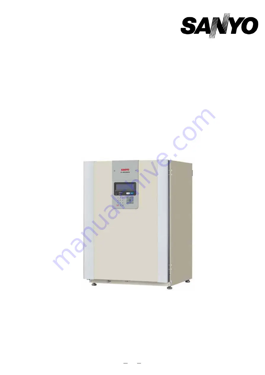
background image

91

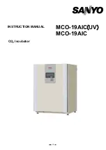
MCO-19AIC

㩿

UV

MCO-19AIC 

CO

2

 Incubator


INSTRUCTION MANUAL


Summary of Contents for MCO-19AIC

Page 1: ...91 MCO 19AIC㩿UV㪀 MCO 19AIC CO2 Incubator INSTRUCTION MANUAL ...

Page 2: ...M PARAMETERS 25 UV LAMP PARAMETERS 26 Using the UV lamp 26 Precautions when using the UV lamp 27 Setting the UV lamp ON period 28 Lighting the UV lamp for 24 hours 29 OTHER PARAMETERS 30 Setting the date time and log interval 30 Initial settings LCD DAQ parameters 32 DISPLAYING THE LOG 33 Transferring data 34 WATER LEVEL SENSOR 35 ROUTINE MAINTENANCE Cleaning the chamber and inner attachments 36 F...

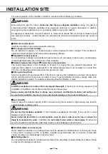
Page 3: ...n a suitable place so that it can be referred to as necessary Ŷ The contents of this manual are subject to change without notice for improvement of performance or functions Ŷ Contact a Sanyo sales representative or agent if any page of the manual is lost or the page order is incorrect Ŷ Contact a Sanyo sales representative or agent if any point in this manual is unclear or if there are any inaccur...

Page 4: ...y Symbol shows this symbol means caution this symbol means an action is prohibited this symbol means an instruction must be followed Be sure to keep this manual in a place accessible to users of this unit Label on the unit This mark is labeled on the cover in which the electrical components of high voltage are enclosed to prevent the electric shock The cover should be removed by a qualified engine...

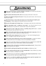
Page 5: ...tlet is not grounded it will be necessary to install a ground by qualified engineers Never ground the unit through a gas pipe water main telephone line or lightning rod Such grounding may cause electric shock in the case of an incomplete circuit Connect the unit to a power source as indicated on the rating label attached to the unit Use of any other voltage or frequency other than that on the rati...

Page 6: ...ling the cord may result in electric shock or fire by short circuit Disconnect the power supply plug before moving the unit Take care not to damage the power cord A damaged cord may cause electric shock or fire Disconnect the power plug when the unit is not used for long periods Keeping the connection may cause electric shock current leakage or fire due to the deterioration of insulation If the un...

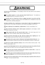
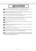
Page 7: ...e of setting Be careful not to tip over the unit during movement to prevent damage or injury Prepare a safety check sheet when you request any repair or maintenance for the safety of service personnel Wear rubber gloves when handling the H2O2 reagent Direct contact with the H2O2 reagent may result in inflammation of the skin H2O2 decontamination can be performed only for the chamber and chamber at...

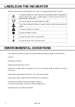
Page 8: ...cates an earth This symbol means ON for a power switch This symbol means OFF for a power switch EMVIRONMENTAL CONDITIONS The Indicator is designed to be safe if used under the following conditions based on the IEC 61010 1 Ŷ Indoors Ŷ Altitudes up to 2000 m Ŷ Ambient temperature from 5 to 40o C Ŷ Maximum humidity of 80 for temperatures up to 31o C decreasing linearly to maximum humidity of 50 at 40...

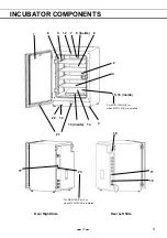
Page 9: ... COMPONENTS 1 2 3 4 5 6 7 8 9 inside 10 12 15 16 inside 13 inside 17 Rear Right Side 11 18 20 Rear Left Side For MCO 19AIC UV or when MCO 19UVS is installed 19 21 22 14 For MCO 19AIC UV or when MCO 19UVS is installed ...

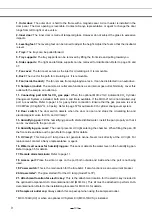
Page 10: ... pressure is set at 0 03 MPaG 0 3 kgf cm2 G 4 3 psiG Refer to page 57 for automatic CO2 cylinder changeover system 12 Door switch The door switch detects when the door is open and stops the circulating fan and electromagnetic valve for CO2 and UV lamp 13 Humidifying pan Fill the humidifying pan with sterile distilled water Install the pan properly so that it can be covered with the pan cover 14 Hu...

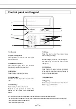
Page 11: ...rature alarm 7 CE Key Press this key to clear the entered value when entering a setting 8 Cursor Keys Up Down Left and Right Use these keys to move the cursor on the LCD panel 9 ENTER Key Press this key to select a menu command When entering a setting pressing this key to move to the next parameter 㩷 10 Numeric Keys 11 H2O2 Key Press this key to start H2O2 decontamination Refer to page 40 for deta...

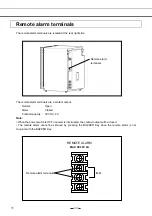
Page 12: ...Normal Open Alarm Closed Contact capacity 30 VDC 2 A Note When the power switch is OFF or power is interrupted the contact output will be closed The remote alarm cannot be silenced by pressing the BUZZER Key since the remote alarm is not conjunct with the BUZZER Key Remote alarm terminals REMOTE ALARM MAX DC30V 2A N O Remote alarm terminals ...

Page 13: ...oor If the floor is uneven or the installation is not level the Incubator will be unstable and this may cause accident or injury To avoid vibration and noise always make sure that the installation is stable An unstable surface may result in vibration or noise WARNING Install the Incubator at a location that can support the weight If the floor is not strong enough or if the installation is insuffic...

Page 14: ... possible then have a ground installed by qualified personnel If the Incubator is not grounded it may result in electric shock Never connect the ground wire to a gas pipe water pipe lightning rod or telephone ground wire Doing so may cause electric shock z Installing a ground fault circuit breaker If using the Incubator in a location with moisture or humidity cannot be avoided then it is recommend...

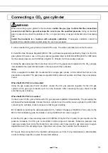
Page 15: ...egulator The gas pressure regulator safety valve will operate and there may an explosive sound When the MCO 21GC is not mounted Using the gas supply pipe that is provided connect the CO2 gas pressure regulator for the CO2 gas cylinder to CO2 gas pipe connection port A on the Incubator After connecting the pipe check to make sure that no gas is leaking When the MCO 21GC is mounted Connect a pair of...

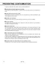
Page 16: ...gerprints If water spills from the humidifying pan or if the doors are left open for a long time condensation may form on the inside of the doors If that occurs wipe off the condensation with a dry sterile gauze In particular clean and disinfect the chamber if the culture medium is spilled For details refer to Routine Maintenance on page 36 z Use sterile distilled water in the humidifying pan Alwa...

Page 17: ...amage to the gasket Before opening the inner door check through the glass to confirm that the UV lamp is OFF if the MCO 19AIC UV or the optional MCO 19UVS is installed z Be careful when closing the outer door Use the handle when closing the outer door Holding the door in other places may cause injury by getting fingers caught in the door Do not lean on the outer door Doing so may result in injury ...

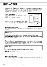
Page 18: ...Use the following procedure to start trial operation or actual operation of the Incubator 1 Install the Incubator correctly referring to Installation on page 13 2 Remove the packing materials from the chamber and inner attachments Clean and disinfect the chamber and inner attachments referring to Routine Maintenance on page 36 3 Add approximately 1 5 L of sterile distilled water to the humidifying...

Page 19: ...Cylinder Changeover System MCO 21GC is installed The port of the CO2 gas pipe that is currently supplying CO2 will be displayed in reverse video Nothing will be displayed if the MCO 21GC is not installed 6 Status display field Various status or alarms are displayed 䊶When UV lamp is lit UV is displayed in reverse video 䊶When humidifying water is low RH PAN is displayed in reverse video 䊶When the do...

Page 20: ...l MCO 19UVS page 26 6 Setting other parameters䊶䊶䊶The initial settings of the date time and log cycle page 30 and the LCD display and baud rate page 32 can be set 7 Displaying the operation log and transferring data䊶䊶䊶A graph of past operation data can be displayed page 33 and operation data can be transferred to a PC page 34 8 H2O2 decontamination䊶䊶䊶H2O2 decontamination of the chamber and internal...

Page 21: ... enter 370 ƔCO2 density 0 to 20 To set 5 0 enter 050 㩷 㩷 3 Press the MENU Key to display the menu after setting the parameters Select OK and press the ENTER Key The settings will be saved 㩷 Note When starting the Incubator for the first time or after not using it for an extended period of time allow at least 4 hours for the chamber temperature humidity and CO2 sensor to become stable after setting...

Page 22: ...d Field Input the 4 digit password default 0000 and press the ENTER Key When key lock is release the buzzer will sound briefly and Key Lock will disappear from the Stand by Setting Display 㩷 㩷 㩷 㩷 㩷 㩷 㩷 㩷 㩷 㩷 1 S t a n d b y S e t t i n g K e y L o c k 2 T e m p e r a t u r e 3 7 0 o C 0 5 0 0 o C 3 C O 2 D e n s i t y 5 0 0 0 2 0 0 4 K e y L o c k 0 P a s s w o r d H i g h L i m i t 5 2 0 o C 1 S...

Page 23: ...ect Key Lock PW Setting from the Select Tools Display press the MENU Key to display the menu select OK and press the ENTER Key 㩷 㩷 㩷 㩷 㩷 㩷 㩷 㩷 㩷 㩷 㩷 3 Input the current user password 4 digits select OK and press the ENTER Key The default user password is 0000 when the Incubator is shipped from the factory 㩷 㩷 㩷 㩷 㩷 㩷 㩷 㩷 㩷 㩷 㩷 S e l e c t T o o l s 1 2 T e m p C O 2 C a l i b r a t i o n A l a r m...

Page 24: ... 㩷 㩷 㩷 㩷 㩷 㩷 㩷 㩷 㩷 㩷 㩷 Note Be careful not to forget the key lock password If you have forgotten the password and cannot release the key lock contact a Sanyo sales representative or agent 㩷 㩷 㩷 㩷 K e y L o c k P W S e t t i n g N e w U s e r P a s s w o r d 㧖 㧖 㧖 㧖 R e E n t e r U s e r P a s s w o r d 㧖 㧖 㧖 㧖 K e y L o c k P W S e t t i n g N e w U s e r P a s s w o r d 㧖 㧖 㧖 㧖 ...

Page 25: ... limit alarm temperature to at least 50o C when H2O2 decontamination is performed 2 After setting the parameter press the MENU Key to display the menu select OK and press the ENTER Key The alarm temperature will be saved Refer to the tables of alarms and safety functions on page 46 for details Note 䊶The alarm temperature will be changed at any time by turning the upper limit regulator even if the ...

Page 26: ... be set 㩷 㩷 㩷 㩷 㩷 㩷 㩷 㩷 㩷 㩷 㩷 䊶Temperature alarm 1 0 to 5 0o C Default 1 0o C 䊶CO2 alarm 0 5 to 5 0 Default 1 0 䊶Alarm delay 0 to 15 minutes Default 15 minutes 䊶Ring back time 1 to 99 minutes or OFF Default 30 minutes 䊶Door alarm delay 1 to 30 minutes Default 2 minutes S e l e c t T o o l s 1 2 T e m p C O 2 C a l i b r a t i o n A l a r m S e t t i n g L C D D A Q S e t t i n g U V S e t t i n g ...

Page 27: ... the outer door is closed The default setting is for five minutes z If the outer door is not opened for at least 12 consecutive hours the UV lamp will light for the preset time period every 12 hours z The recommended replacement time for the UV lamp i e when the UV output ratio drops to 60 to 70 of its initial value is when the accumulated ON time reaches 1 000 hours When the accumulated ON time r...

Page 28: ... the UV lamp is lit open the outer door and then press the door switch with the inner door still closed Visible blue light can be confirmed from the front of the humidifying pan cover UV light is harmful to the eyes so do not light the UV lamp when the inner door or humidifying pan cover is open z Be careful when handling the UV lamp There is a UV lamp inside of the chamber duct Be careful not to ...

Page 29: ... the UV Timer for the UV lamp ON period 㩷 㩷 㩷 㩷 㩷 㩷 㩷 㩷 㩷 㩷 㩷 4 Press the MENU Key to display the menu select OK and press the ENTER Key The parameter will be saved 㩷 㩷 1 T e m p 3 7 0 o C C O 2 5 0 2 3 4 5 S t a t u s 6 O K 7 㧟㧣 㧜 㧡 㧜 M E N U S e t L o g T o o l s S e l e c t T o o l s 1 2 T e m p C O 2 C a l i b r a t i o n A l a r m S e t t i n g L C D D A Q S e t t i n g U V S e t t i n g K e ...

Page 30: ...ours 㩷 1 Remove all attachments from the chamber including the trays tray supports side supports fan cover duct fan humidifying pan and humidifying pan cover Clean all the attachments in an autoclave or with disinfectant alcohol 2 Clean and wipe off inside the chamber with disinfectant alcohol 3 Set the CO2 density to 0 and set the UV 24h Mode to 1 on the UV Setting Display 㩷 㩷 㩷 㩷 㩷 㩷 㩷 㩷 㩷 㩷 㩷 4...

Page 31: ...y press the MENU Key to display the menu select OK and press the ENTER Key 㩷 㩷 㩷 㩷 㩷 㩷 㩷 㩷 㩷 㩷 㩷 㩷 㩷 㩷 㩷 㩷 㩷 㩷 㩷 㩷 㩷 㩷 㩷 㩷 㩷 㩷 㩷 㩷 㩷 1 T e m p 3 7 0 o C C O 2 5 0 2 3 4 5 S t a t u s 6 O K 7 㧟㧣 㧜 㧡 㧜 M E N U S e t L o g T o o l s S e l e c t T o o l s 1 2 T e m p C O 2 C a l i b r a t i o n A l a r m S e t t i n g L C D D A Q S e t t i n g U V S e t t i n g K e y L o c k P W S e t t i n g D a t e ...

Page 32: ...ote Ŷ The default is 6 minutes Ŷ The log interval can be set to between 2 and 30 minutes Ŷ Relation between the log interval and the period that can be saved 1 Log interval of 2 minutes About 5 days 2 Log interval of 6 minutes About 14 days 3 Log interval of 30 minutes About 70 days For the data beyond the above period the older data is deleted to save the newer data 㩷 㩷 1 D a t e T i m e 3 D a t ...

Page 33: ...to set the DAQ speed DAQ ID and DAQ mode to use the optional communications software A special order is required for communications software Contact a Sanyo sales representative or agent for details 㩷 㩷 1 L C D D A Q S e t t i n g 3 L C D B a c k C o l o r 1 1 B l u e 2 W h i t e D A Q S p e e d 0 0 2 4 2 9 6 3 3 5 0 4 D A Q I D 0 0 O F F 1 2 5 5 5 D A Q M o d e 0 0 L o c a l 1 R e m o t e R e m o...

Page 34: ...sor Key to switch between the temperature and CO2 density displays Press the Left Cursor Key and Right Cursor Key to scroll the displayed data Left Cursor Key older data Right Cursor Key newer data 㩷 㩷 㩷 㩷 㩷 㩷 㩷 㩷 㩷 㩷 㩷 㩷 㩷 㩷 㩷 㩷 㩷 㩷 㩷 㩷 㩷 㩷 㩷 㩷 㩷 㩷 㩷 㩷 㩷 1 T e m p 3 7 0 o C C O 2 5 0 2 3 4 5 S t a t u s 6 O K 7 㧟㧣 㧜 㧡 㧜 M E N U S e t L o g T o o l s 1 5 0 C 2 0 0 9 0 3 0 1 T e m p 3 4 5 6 0 1 2 2...

Page 35: ... log data For Windows 2000 and Windows XP 1 From the Windows Start Button select Program㩷 㪄 Accessories㩷 㪄 Communications㩷 㪄 HyperTerminal to start the HyperTerminal If the HyperTerminal is not available from the Start Menu execute the following file C Program Files Windows NT hypertrm exe 2 In the HyperTerminal Window set a new connection the name for example Sanyo connection settings method of c...

Page 36: ... if the sensor does not come down completely If necessary set the pan again in the proper location The sensor detects the water level every 30 minutes and just after the outer door is closed It takes several seconds to detect the water level Therefore RH PAN may displayed in reverse video several times in the status display field on LCD panel after the outer door is closed even when the humidifyin...

Page 37: ...rmful to health CAUTION Wear rubber gloves when performing maintenance on the chamber Failure to wear gloves may result in cuts or abrasions from sharp edges or corners Note Be careful not to damage the humidifying pan water level sensor or the UV lamp in the chamber duct if the MCO 19AIC UV or the optional MCO 19UVS is installed Do not use detergents or antiseptic solutions with acid alkali or ch...

Page 38: ...remove it from the pins on the rear side See Fig 6 8 Remove the chamber circulation fan by pulling out the central spring and then by pulling out the fan See Fig 7 9 Remove the screw securing the clamp for the tray brace See Fig 8 10 Remove the clamp See Fig 9 11 Lift the tray brace off of the pins See Fig 10 Fig 7 Fig 8 Fig 9 Fig 10 Fig 4 Fig 5 Fig 6 ...

Page 39: ...y residual alcohol When cleaning the sensor take care not to apply excessive force to the lead wires 15 To reinstall all the attachments perform the procedure in reverse order from step 14 Note When installing the chamber circulation fan insert it securely on the motor shaft Lightly turn the fan manually to make sure that it does not strike the rear panel Improper insertion may cause poor performa...

Page 40: ... L preheated to 37qC See Fig 3 6 Set the pan with the inner side flush against the back and replace the cover Close the inner and outer doors and confirm that RH PAN is not displayed in reverse video in the status display area Note Preheat to 37qC the water to be added to the humidifying pan Adding low temperature water will lower the temperature and humidity in the chamber If the water level alar...

Page 41: ... the upper limit temperature alarm to 50qC or higher z For the H2O2 reagent use one bottle of the H2O2 Decontamination Reagent specified by Sanyo MCO H202 z After decontamination dilute the residual H2O2 Decontamination Reagent in the H2O2 Generator with a large quantity of water and dispose of it and rinse with distilled water Do not wash either the inside or outside of the H2O2 Generator with al...

Page 42: ...es when handling the H2O2 reagent Direct contact with the H2O2 reagent may result in inflammation of the skin CAUTION After H2O2 decontamination has been completed residual H2O2 solution will remain on the bottom of the chamber the H2O2 Generator and the bottom of the duct Wearing protective glasses and rubber gloves wipe it off with a non woven cloth Failure to do so may result in a deficient cul...

Page 43: ...ation Reagent MCO H2O2 into the H2O2 Generator Set the two pins on the H2O2 Generator in the 2 holes on the lower left side of the duct Fig 1 4 Connect the H2O2 Generator and connector on the bottom right of the far side of the chamber with the enclosed cable Be sure to keep the connector cap Fig 1 5 Set the humidifying pan cover humidifying pan and fan cover as shown in Fig 2 and close the inner ...

Page 44: ...rming up Note The outer door will be locked with an electric lock for safety until the decontamination has been completed 8 During the H2O2 mist generation H2O2 Decon will flash at the top left corner of the screen Note H2O2 mist generates from the H2O2 Generator and then quickly changes to a gas 1 H 2 O 2 D e c o n t a m i n a t i o n 3 4 R e a d y t o S t a r t 5 6 M E N U O K C a n c e l 1 H 2 ...

Page 45: ...sses and rubber gloves when performing decontamination 11 The following display will appear Press the MENU Key to display the menu select OK and press the ENTER Key to return to the Top Display 1 H 2 O 2 D e c o n t a m i n a t i o n S t e p 8 2 3 D e c o n F i n i s h e d 4 5 T e m p 4 5 0 㷄㩷 6 P l e a s e R e m o v e H 2 O 2 U n i t D o o r U n l o c k 7 1 H 2 O 2 D e c o n t a m i n a t i o n S...

Page 46: ...ination will be incomplete WARNING Never open the door by unlocking it with the unlock key during H2O2 decontamination or H2O2 gas resolution with the UV lamp H2O2 gas leakage is potentially harmful to health Precautions when handling H2O2 decontamination reagent Observe the following precautions when handling the H2O2 Decontamination Reagent MCO H2O2 㩷 㩷 z Handling Precautions x Wear protective e...

Page 47: ...nsor is short circuited Err06䋺Temp Sensor Short is displayed in the message display field 䇰 The heater turns OFF Remote alarm operates The sensor box temperature sensor is disconnected Err07 CO2S Box Temp Sensor Open is displayed in the message display field 䇰 CO2 valve is closed Remote alarm operates Sensor box temperature sensor error The sensor box temperature sensor is short circuited Err08䋺CO...

Page 48: ...eld After completion Decon Failed is displayed in the screen center Intermittent tone Electrically locked during power interruption After power is restored moves to UV analysis Remote alarm operates The UV lamp failed during H2O2 gas analysis by UV Err36 UV Lamp Failure is displayed in the message display field Intermittent tone UV analysis time is extended Remote alarm operates Failure during H2O...

Page 49: ...pan Enter 365 㩷 㩷 㩷 㩷 㩷 㩷 㩷 㩷 㩷 㩷 㩷 S e l e c t T o o l s 1 2 T e m p C O 2 C a l i b r a t i o n A l a r m S e t t i n g L C D D A Q S e t t i n g U V S e t t i n g K e y L o c k P W S e t t i n g D a t e T i m e M E N U O K S v c C a n c e l 1 T e m p 3 7 0 o C C O 2 5 0 2 3 4 5 S t a t u s 6 O K 7 㧟㧣 㧜 㧡 㧜 M E N U S e t L o g T o o l s 0 1 0 2 0 3 0 4 0 5 0 6 0 7 0 8 0 9 1 0 1 1 1 2 1 3 1 4 1 5...

Page 50: ... several points The temperature setting must not change by more than r1 0o C and the CO2 density must not change by more than r1 0 during calibration If these values are exceeded an error buzzer will sound the input data will be ignored and the Incubator will return to the display mode If it is necessary to change the temperature by more than 1 0o C or the CO2 density by more than 1 0 perform cali...

Page 51: ... pipe come loose or is there a gas leak x Has the CO2 gas concentration setting been changed x Is the gas cylinder empty Check the primary pressure of the gas cylinder once a week When the primary pressure is 3 8 MPa 38 kgf cm 2 G or lower it is a sign that there is little gas remaining Replace the cylinder soon The chamber temperature does not match the set value x Is the ambient temperature less...

Page 52: ...approaches the set value Injections may be stopped for periods of approximately 15 seconds but that is not an error The outer door does not open When the optional MCO HL is installed x When the power is OFF the electric lock is locked and the outer door does not open Either turn ON the power or use the accessory unlock key to override the electric lock x During decontamination the outer door is el...

Page 53: ...ot have access to the Incubator and that the Incubator doors cannot be completely closed If the doors can be closed it may be possible for children to become locked inside The Incubator must be dismantled and disposed of by qualified personnel only If the doors are not removed it may be possible for children to become locked inside ...

Page 54: ... help us to conserve the environment we live in German Ihr SANYO Produkt wurde entworfen und hergestellt mit qualitativ hochwertigen Materialien und Komponenten die recycelt und wiederverwendet werden können Dieses Symbol bedeutet daß elektrische und elektronische Geräte am Ende ihrer Nutzungsdauer von Hausmüll getrennt entsorgt werden sollen Bitte entsorgen Sie dieses Gerät bei Ihrer örtlichen ko...

Page 55: ...e manière inappropriée peuvent s avérer potentiellement dangereuses pour la santé humaine et pour l environnement Cependant ces matières sont nécessaires au bon fonctionnement de votre appareil ou de votre machine Pour cette raison il vous est demandé de ne pas vous débarrasser de votre appareil ou machine usagé avec vos ordures ménagères Spanish Los productos SANYO están diseñados y fabricados co...

Page 56: ...s de recolha separados para produtos eléctricos e electrónicos usados Por favor ajude nos a conservar o ambiente em que vivemos Italian Il vostro prodotto SANYO è stato costruito da materiali e componenti di alta qualità che sono riutilizzabili o riciclabili Prodotti elettrici ed elettronici portando questo simbolo alla fine dell uso devono essere smaltiti separatamente dai rifiuti casalinghi Vi p...

Page 57: ...ektronische apparatuur bij de daarvoor wettelijke instanties aangeboden Alstublieft help allen mee om het milieu te beschermen Swedish Din SANYO produkt är designad och tillverkad av material och komponenter med hög kvalitet som kan återvinnas och återanvändas Denna symbol betyder att elektriska och elektroniska produkter efter slutanvändande skall sorteras och lämnas separat från Ditt hushållsavf...

Page 58: ...ed to the CO2 gas pipe connected to port B 㩷 3 Open the valves of both gas cylinders 㩷 4 The current CO2 gas supply line is displayed on the Top Display A and B will be displayed only when the MCO 21GC is installed Nothing will be displayed if MCO 21GC is not installed 㩷 㩷 㩷 㩷 㩷 㩷 㩷 㩷 㩷 㩷 㩷 㩷 㩷 㩷 5 The MCO 21GC detects that there is no more CO2 gas in a cylinder when the CO2 density in the chamber...

Page 59: ...ricting of gas tube reduction of CO2 gas pressure or improper opening of CO2 gas cylinder Always check the gas quantity in the cylinder before disconnecting it 㩷 Ɣ Use the following procedure to manual switch the line between CO2 cylinders A and B only when MCO 21GC is installed This procedure shows switching the line from㩷 CO2 cylinder B to A as an example 㩷 㩷 1 From the Top Display press the Lef...

Page 60: ...㩷 㩷 㩷 㩷 2 Press the Down Cursor Key from the Select Tools 1 2 Display to display the Select Tools 2 2 Display and then select Standard Gas Setting press the MENU Key to display the menu select OK and press the ENTER Key 㩷 㩷 㩷 㩷 㩷 㩷 㩷 㩷 㩷 㩷 㩷 㩷 㩷 㩷 㩷 㩷 㩷 㩷 㩷 㩷 㩷 㩷 㩷 㩷 㩷 㩷 1 T e m p 3 7 0 o C C O 2 5 0 2 3 4 5 S t a t u s 6 O K 7 㧟㧣 㧜 㧡 㧜 M E N U S e t L o g T o o l s S e l e c t T o o l s 2 2 S t a...

Page 61: ...menu select OK and press the ENTER Key 㩷 㩷 㩷 㩷 㩷 㩷 㩷 㩷 㩷 㩷 㩷 2 The system check will start 㩷 㩷 㩷 㩷 㩷 㩷 㩷 㩷 㩷 㩷 㩷 㩷 㩷 㩷 㩷 㩷 㩷 㩷 S e l e c t T o o l s 2 2 S t a n d a r d G a s S e t t i n g S t a n d a r d G a s C a l i b r a t i o n M E N U O K S v c C a n c e l 1 S t a n d a r d G a s S e t t i n g 3 C O 2 S T D G a s D e n s i t y 5 0 4 5 6 M E N U O K C a n c e l 1 S t a n d a r d G a s C a l i...

Page 62: ... 㩷 㩷 㩷 㩷 㩷 㩷 㩷 㩷 㩷 㩷 㩷 㩷 㩷 㩷 㩷 㩷 㩷 㩷 㩷 㩷 㩷 㩷 㩷 㩷 㩷 㩷 㩷 㩷 㩷 㩷 㩷 㩷 㩷 㩷 㩷 㩷 㩷 㩷 㩷 㩷 㩷 㩷 1 S t a n d a r d G a s C a l i b r a t i o n 3 R e a d y t o S t a r t 4 5 C O 2 㧦 0 0 S T G 㧦 5 0 6 M E N U O K C a n c e l 1 S t a n d a r d G a s C a l i b r a t i o n S t e p 㧦 3 3 S t d G a s C a l i b r a t i n g 4 5 C O 2 㧦 4 8 S T G 㧦 5 0 6 1 T e m p 3 7 0 o C C O 2 5 0 2 3 4 5 S t a t u s 6 O K 7 㧟㧣 㧜 㧡 ...

Page 63: ...crews wiring connectors in 3 places ground wire and gas pipe from the Incubator that is to be on the top 6 Place the upper Incubator on top of the lower one being careful not to pinch your fingers 7 Make the lower Incubator level by adjusting the legs and then level the upper Incubator in the same way 8 Secure stacking bracket A to the upper and lower Incubators with the accessory screws 9 Remove ...

Page 64: ...154 Fig A Stacking plate B Stacking plate A Protective sticker Front panel Hook Front 63 ...

Page 65: ...ion Water level sensor Optical Alarms Automatic set temperature alarm Automatic set CO2 density alarm Upper limit temperature alarm Door alarm Low humidifying water alarm UV lamp failure alarm for UV equipped model only Remote alarm contacts Allowable contact capacity 30 VDC 2 A CO2 inlet connection 4 to 6 mm diameter tube CO2 inlet pressure 0 03 MPaG 0 3 kgf cm2 G 4 3 psiG Accessories 4 trays 4 s...

Page 66: ...n 0 15 ambient temperature 25o C setting 37o C CO2 5 no load Chamber humidity 95 5 Maximum heat emission 1 120 kJ h Applicable environment condition Temperature 5 to 35o C Humidity 80 max The designed performance may not be obtained if the ambient temperature is equal or less than 15o C Noise level 30 dB A scale Maximum power consumption 350 W 310 W 110 to 120 V 60 Hz 220 to 240 V 50 Hz Total maxi...

Page 67: ...ions for safe repair maintenance of the unit a The unit is safe to work on b There is some danger see below Procedure to be adhered to in order to reduce safety risk indicated in b below Date Signature Address Division Telephone Product name CO2 incubator Model MCO 19AIC UV MCO 19AIC Serial number Date of Installation Please decontaminate the unit yourself before calling the service engineer غ Yes...

Page 68: ...SANYO Electric Co Ltd Printed in Japan ...

Reviews: