background image

SERVICE MANUAL

PRODUCT CODE No.
1 682 

349


49

: PAL-BG(TV) DTV

FILE NO.

PRODUCT CODE No.

REFERENCE No.:

SM0915102

LED-42XR10FH


LED-LCD TV

Summary of Contents for LED-42XR10FH

Page 1: ...SERVICE MANUAL PRODUCT CODE No 1 682 349 49 PAL BG TV DTV FILE NO PRODUCT CODE No REFERENCE No SM0915102 LED 42XR10FH LED LCD TV ...

Page 2: ...s Working principle analysis of the unit Block diagram IC block diagram and instruction Wiring diagram Troubleshooting guide Schematic diagram APPENDIX A Main assembly list APPENDIX B Exploded View 3 5 13 17 19 20 29 30 33 Wall mounting instructions Installing the Stand or wall mount bracket ...

Page 3: ...will result 2 5 If any foreign substance such as water liquid metal slices or other matters happens to fall into the module be sure to cut the power off immediately and do not move anything on the module lest it should cause fire or electric shock due to contact with the high voltage or short circuit 2 6 Should there be smoke abnormal smell or sound from the module please shut the power off at onc...

Page 4: ... 20 80 Scope for storage 80 2 13 Display of a fixed picture for a long time may result in appearance of picture residue on the screen as commonly called ghost shadow The extent of the residual picture varies with the maker of LED screen This phenomenon doesn t represent failure This ghost shadow may remain in the picture for a period of time several minutes But when operating it please avoid displ...

Page 5: ... 9 10 11 12 13 Vol 2 5 V 0 5 V 5 0 5 V 5 N C 0 12 V 5 0 2 0 V 2 5 V b Test each pin voltage of 5 pin power socket X606 in turn 26 models please refer voltage to Table 3 Table 3 Each pin voltage of 5 pin power socket Pin 1 2 3 4 5 Vol 24 V 5 0 Alignment instructions 2 Test equipment VG 848 VGA YPbPr signal generator VG 849 HDMI digital video signal generator CA210 color analyzer 1 Safety Instructio...

Page 6: ...t of earphones and speakers are normal Input composite AV signal check if AV functions are normal Accessories checkup and packing Setup before shipment Other functions checkup such as LCN OTA etc Input digital HDMI signal check if display and other functions are normal analog parameters control H V center etc Insert USB check its functions Input component signal YPbPr check if YPbPr functions are ...

Page 7: ...DDC functions of D SUB port will recover k Factory menu item EEPROM Init for factory and customer data initialization TV set will reset and initial guiding interface will display after executing the item l Factory menu item Fac Channel Preset for factory channels presetting it is necessary to connect to central signal source before operating the item now digital frequency of central signal CH28 52...

Page 8: ...al VG848 Timing 856 1024 768 60 Hz Pattern 914 Color Temp move cursor to item MODE press keys and to select item RGB then move cursor to item AUTO ADC and press key OK to begin auto adjustment until prompt Success displays which means successful auto calibration 4 2 White balance adjustment Unless specified by customer a 26 models Default color temperature Cool is 10000K and its chromatic coordina...

Page 9: ...dinate of X will increase when R gun is adjusted upwards coordinate of X will decrease when R gun is adjusted downwards G Gun adjusting G gun will effect coordinate of Y and value of Lv greatly coordinate of Y will increase when G gun is adjusted upwards coordinate of Y will decrease when G gun is adjusted downwards 5 Functions checkup 5 1 Analog digital TV functions Input central signal to RF por...

Page 10: ...atically Table 5 Analog RGB signal formats No Definition H fre kHz V fre Hz Dot pulse fre MHz Note 1 640 480 31 469 59 94 25 175 IBM 2 720 400 31 469 70 086 28 322 IBM 3 640 480 37 861 72 809 31 5 VESA 4 640 480 37 5 75 31 5 VESA 5 800 600 35 156 56 25 36 VESA 6 800 600 37 879 60 317 40 VESA 7 800 600 48 077 72 188 50 VESA 8 800 600 46 875 75 49 5 VESA 9 1024 768 48 363 60 004 65 VESA 10 1024 768 ...

Page 11: ... 59 94 60 Hz 11 720 576 31 25 50 27 720 576p 50 Hz 4 3 16 9 12 1280 720 37 5 50 74 25 1280 720p 50 Hz 13 1920 1080 28 125 50 74 25 1920 1080i 50 Hz 14 720 1440 576 15 625 50 27 720 1440 576i 50 Hz 4 3 16 9 15 720 1440 288 15 625 Mode 1 49 761 27 Mode 2 49 92 Mode 3 50 08 16 2880 576 15 625 50 54 2880 576i 50 Hz 4 3 16 9 720 1440 288p 50 Hz 4 3 16 9 17 2880 288 15 625 Mode 1 49 761 54 Mode 2 49 92 ...

Page 12: ...ions of LCN OTA are normal 6 User menu setup before shipment Enter into LOCK user menu input initial password 0000 select item Restore Factory Default and then press key OK to make setup before shipment a Clear out information of all programs b Clear out information of program lock favorite programs etc c Recover default analog parameters d Set menu language as English e Set power on mode as Stand...

Page 13: ...06 5272404002 AT24C04IV 10SU 2 7 HDCP KEY Yes Use ALL 100 etc N302 N305 N316 5272402002 AT24C02BN10SU 1 8 HDMI EDID Yes Use ALL 100 etc 26 LED N309 5272402002 AT24C02BN10SU 1 8 VGA EDID Yes Use ALL 100 etc Note 1 Method of write protect setup enter into burning interface of ALL 100 tick option Config press item config Setting set option Protect as All Protect make sure that option Config must be t...

Page 14: ...to Fig 3 if connection is failed press the first menu Device to select SPI Flash type manually then press menu Connect again Fig 3 Successful connection d Press menu Read select the burning file such as MERGE bin please refer to Fig 4 Fig 4 Burning file e Press menu Auto tick options All chip program and relative option switches please refer to Fig 5 press key Run to begin burning ...

Page 15: ... it is passed by quickly please confirm procedure 2 and begin burning process again 2 Then the following step is Programming 3 A prompt Pass will display at last g A prompt Pass will display if burning process is successful please refer to Fig 7 Fig 7 Successful burning process h If there are other machines to be burned remain ISP burning interface and repeat procedures c to e only ...

Page 16: ...USB memory to begin upgrade detailed upgrading processes are below 1 Read data from USB memory a prompt Unknown image type will display if upgrading file is wrong 2 If upgrading file is right a prompt Software upgrading and percent of upgrading progress will display while indicated light is twinkling at the same time 3 The unit will restart after upgrading processes has completed e Restart the uni...

Page 17: ... to be demodulated to analog audio signal then it is sent to earphone amplifier BH3547F to be amplified after the processes of preamplification acoustic effect processing and volume control and then it is divided into two one is sent to earphone jack the other is sent to audio power amplifier R2A15112FP D class to be amplified and then drive speakers 2 DVB T signal flow Send DVB T digital RF signa...

Page 18: ...nt into main chip MSD209GL for acoustic effect processing and volume control after the processing of voltage division impendence matching and AC coupling then it is sent to earphone amplifier BH3547F to be amplified one is sent to earphone jack the other is sent to audio power amplifier R2A15112FP D class to be amplified and then drive speakers 5 HDMI input signal flow HDMI video signal is sent in...

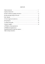
Page 19: ...Blockdiagram ...

Page 20: ...s from external sources such as USB interface For analog TV the MSD209GL includes NTSC PAL SECAM multi standard video decoder comprising a 3D motion adaptive comb filter and time based correction and a NICAM A2 audio decoder to support worldwide television standards The MSD209GL is also configured with a VBI processor to decode digital information such as Close Caption V chip teletext WSS CGMS A V...

Page 21: ...S streams extractions and provision of time stamps RealMedia Decoder z Supports maximum resolution up to 720p 30fps z Supports RV8 RV9 RV10 RA8 LBR and HE AAC decoders z Supports file formats with RM and RMVB z Supports Picture Re sampling z Supports in loop de block for B frame Hardware JPEG z Supports sequential mode single scan z Supports both color and grayscale picture z Operates in scan unit...

Page 22: ...orts z Three analog ports support up to 1080P z Supports PC RGB input up to SXGA 75Hz z Supports HDTV RGB YPbPr YCbCr z Supports Composite Sync and SOG Sync on Green separator z Automatic color calibration Auto Configuration Auto Detection z Auto input signal format and mode detection z Auto tuning function including phasing positioning offset gain and jitter detection z Sync Detection for H V Syn...

Page 23: ...rts up to 10 bit dual LVDS full HD 1920 x 1080 panel interface z Supports 2 data output formats Thine TI data mappings z Compatible with TIA EIA z With 6 8 bits optional dithered output z Spread spectrum output frequency for EMI suppression CVBS Video Output z Supports CVBS bypass output z Built in video encoder for encoding digital video into CVBS output 2D Graphics Engine z Point draw line draw ...

Page 24: ...lity z Independent ADC controls for IF and RF z Configurable parallel serial MPEG 2 transport stream interface z Impulse Noise suppression z Advanced performance for SFN networks z Supports single or dual AGC control z Direct 36MHz 44MHz IF sampling scheme from tuner z Full digital frequency offset recovery with wide acquisition range 500kHz z IQ imbalance compensation for ZIF Integrated VIF recei...

Page 25: ... in compliance with the European ATV standards for analogue as well as with the terrestrial standard ETS 300 744 and cable standard ETS 300429 for digital It consists of a 3 band RF tuner which receives RF signal and down converts it to an IF frequency of 36MHz for digital and 38 9MHz for analog IF The analogue IF output can directly drive a SAW filter A digital IF Stage which consists of one SAW ...

Page 26: ...r out put No external heat sink note These apply when the thermal pad is soldered to the printed circuit board directly Recommended Power Condition SE operation mode 15Wx2ch VD 24V 4Ω load THD N 1 BTL operation mode 30Wx1ch VD 21V 8Ω load THD N 10 z Highly efficient low noise and low distortion z Popless z Built in protection Overcurrent overheat and undervoltage z Built in Mute and Standby functi...

Page 27: ...upports 2 4 phase output z Supports left right screen partition z Supports TH TI format z Supports dithering options z Spread spectrum output frequency for EMI suppression Video Processing z MFCPRO Motion Frame Conversion Professional supports z Wider searching range z Refined judder free motion video and film z Motion blur elimination to improve MPRT z Advanced halo and artifact elimination z Out...

Page 28: ...ng z Splits screen demo for motion frame conversion Miscellaneous z Embedded 8 bit Microcontroller z Supports 16 bit DDR2 interface z Supports I2C SPI PWM and GPIOs z Supports booting from internal SRAM external EEPROM and SPI flash z 216 pin LQFP package ...

Page 29: ...WIRING DIAGRAM Key Board IR Light sencor Board Sound Box Board Backlight Board Main Board Board Power Board Sound Box Bass Panel Sound Box Amp Power Bass Power Key IR Light sensor Debug Power Switch ...

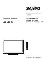
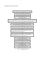
Page 30: ...Troubleshooting guide LED 42XR10FH 1 No Backlight ...

Page 31: ...2 No Picture but backlight is normal ...

Page 32: ...ed circuits Check if N609 12 25 has input signal Check if voltage of N609 10 27 is high level Check peripheral circuits of power amplifier Check mute circuits of power amplifier Check if N320 3 5 has input signal Check earphone amplified circuits Check audio output circuits of main chip Yes Yes Yes Yes No No No No ...

Page 33: ... 6 WP 7 Vcc 8 R112 100 CVBS LOUT 003 D6 UART RX 003 A5 003 A1 005 D1 R132 33 HDMI3 RXC 003 G1 L104 BG1608B121 RXO1 004 B1 CVBS ROUT 003 D5 R101 1K 1 HDMI2 RX0 003 A4 C140 10u GND D 3 3V ADC YPBPR Y_IN 003 D1 SCL 002 D3 004 B2 005 C2 L110 BG1608B121 R107 47 C114 1n SDA 002 D3 004 B2 005 C2 3 3V VIF G101 12MHz HDMI1 RX0 003 A2 HDMI2 HP 003 B4 1 8V DDR2 MVREF 3 3V VDD 1 2V VDDC RFAGC SEL 002 C2 RXOC ...

Page 34: ...3 44 TS_DATA 2 45 TS_DATA 1 46 TS_DATA 0 47 VDDC_47 48 RF_AGC TP201 GND D SDA 001 C1 004 B2 005 C2 V204 BC847AW GND D L202 BG1608B121 C240 10n R214 10K V201 BC847AW R219 33 R217 33 3 3V DE R231 33 GND D R216 1K R245 10K R213 1K R218 4 7K 47 R202 TSDATA 001 E4 47 R205 3 3V DE R224 6 8K 12V C213 1n 12V AIF 1 2V DE R246 10K R223 33 5V TSVALID 001 E3 GND D V203 2SC4215 3 3V DE R203 47 R208 2K 1 2V VDD...

Page 35: ... 5V 5V HDMI2 R365 75 CVBS ROUT 001 B6 AU REF 75 R354 GND D R369 10K 220MHz Z301 HDMI3 SDA 001 D5 47 R360 R344 10K GND D 5V HDMI2 GND D GND D 24C02N 10SI27 N316 AO 1 A1 2 A2 3 GND 4 SDA 5 SCL 6 WP 7 Vcc 8 HDMI2 SDA 001 C5 10K R330 X303 HDMI 18 11 4 17 7 14 3 2 10 13 6 19 9 1 16 5 12 15 8 R317 10 CVBS1_IN 001 B4 C365 10u AMP LIN 005 F2 005 F4 5V HDMI1 N310 PESD5V0L4UG 1 2 3 4 5 47p C310 5V HDMI1 RX0...

Page 36: ...100 R445 100 R446 100 R448 100 R449 100 R452 100 R457 100 R454 100 R451 100 R458 100 R455 100 1 GND_1 2 SDAS 3 SCLS 4 GPIO 8 5 GPIO 9 6 GND_6 7 VDDC_7 8 GPIO 10 9 GPIO 11 10 GPIO 12 11 GPIO 13 12 PDI 13 BIST 14 GPIO 14 15 VDDP_15 16 GND_16 17 VDDC_17 18 MDATA 4 19 MDATA 3 20 GND_20 26 GND_26 27 MDATA 9 28 MDATA 14 29 AVDD_DDR_29 30 DQM 1 31 DQM 0 32 GND_32 33 DQS 0 34 DQSB 0 35 AVDD_DDR_35 36 VDDP...

Page 37: ...4558CM E1 1 OUT1 2 3 4 5 6 7 OU2 8 GND D 12V HPS C643 10u R646 10K C641 10u R653 47K HPS REF 12V AMP RIN 003 G3 005 F4 AMP LIN 003 G4 005 F4 R650 470 C645 4 7n C647 4 7n C646 4 7n C649 4 7n C648 4 7n R655 470 C650 4 7n R649 0 R648 0 R652 150K R657 150K R651 33K R656 33K N611 R2A15112FP 1 OUT1_1 2 OUT1_2 3 NC3 4 VD1_4 5 VD1_5 6 NC6 7 NC7 8 NC8 9 NC9 10 STBYL 11 GAIN1 12 IN1 13 CBIAS 14 ROSC 15 AVCC...

Page 38: ...D1 24 ADD0 25 SCLK 26 SDA 27 INT 28 GPIIO7 29 GPIO6 30 GPIO5 31 GPIO4 32 DVSS 33 GPIO3 34 GPIO2 35 GPIO1 36 GPIO0 37 NC 38 THD1 39 THD0 40 CIN0 GND V33 C4 1u V33 D 0 7 C5 100p C8 100n R12 0 R9 20K PAD7 LED3 LED6 R4 100 LED8 R13 5 6K X1 1 2 3 4 5 6 R6 10K C7 100n 5V LED1 TP2 KEY PAD2 V33 R914 3K R912 3K GND R913 47 GND GND R904 2 7K R903 100 N902 HRM138CB5400 Vout GND Vcc GND N901 ISL29001 1 VDD 2 ...

Page 39: ...5 100p D519 CD4148WP H R542 1K C528 4 7n R520 470K 3 1 4 6 R557 2 2K FU501 IEC 5AL 250V UL 5A 250V C538 4 7n BON BON C565 100n C539 470p 2KV C548 220u 25V R525 680 C510 100n N504 TLP781 R502 1M D523 R535 2 2K D522 FR105P D516 MMSZ5254B H L501 V507 MMBT3904 R545 10K N503 SSC9512 1 Vsen 2 VC1 3 FB 4 GND 5 SS 6 OC 7 RC 8 RV 9 VC2 10 PGND 11 VGL 12 NC12 13 VB 14 VS 15 VGH 16 NC16 C563 220u 25V H N505 ...

Page 40: ...515 220p 1KV C551 220n D505 CD4148WP C569 100n C549 1000p D504 RM3A C503 0 22u 275VAC R578 30K D502 BHS600V 15 20 R552 1K X501 1 2 R537 10K C521 47u 63V 24VCF C511 47n R550 56 X504 1 2 3 4 5 6 7 8 9 10 11 12 13 14 R573 L503 L101 3A R538 2 4K X503 1 2 3 4 5 6 7 8 9 10 11 12 13 V_9500 V_20 D513 MMSZ5245B 5VSB 5VSB N515 AO4803A 1 S2 2 G2 3 S1 4 G1 5 D1_5 6 D1_6 7 D2_7 8 D2_8 R560 47K R517 1M N511 LM4...

Page 41: ...567 100n R573 3 3K R523 2 7K C547 4 7u D505 CD4148WP R509 0 22 2W C560 470u 35V 32V C536 1000u 25V N503 3 1 IN 2 OUT V_9500 R555 100K C509 100p ON OFF R529 47K D509 FR103 3 1 4 6 C554 220p 1KV C550 10p 1KV R527 22 V502 2SA1013 0 R569 47 RT502 2 C512 220n Standby D515 MMSZ5245B C594 100n R515 1M C544 1000p R542 1K 24VCF R538 1 6K V509 S D G Standby V507 BC857B C578 C516 100p R576 2 2K C540 47u 63V ...

Page 42: ...1 N201 N609 N103 TUNER201 MSD209GL LF 5270209002 K4T1G164QE HCF7 5270164002 MST6M20S 5270620001 MSB1210 LF 5271210001 R2A15112FP 5271511201 EN25Q64 104HIP 5272564002 FT2130 5524050027 IR board XI6KH0050910 Key board XI6KQ0020510 Power board XI6HT0252010 Remote control XI6010900501 RC 905 0A Panel XI5203428309 T420HW07 V0 ...

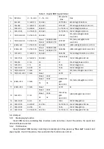
Page 43: ...APPENDIX B Exploded view LED 42XR10FH ...

Page 44: ...ox assembly 4 Power switch 5 Display panel 6 Pedestal bracket right 7 Pedestal bracket left 8 Main board assembly 9 Back cover assembly 10 Standing pole assembly 11 Pedestal assembly 12 Power board assembly 13 Key board assembly Note design and specification are subject to change without notice ...

Page 45: ...8A0086400 Pedestal bracket left 1 8 XI6KH0120110 Main board assembly 1 9 XI674251H040 Back cover assembly 1 10 XI6156106000 Standing pole assembly 1 11 XI6151218000 Pedestal assembly 1 12 XI6HT0252010 Power board assembly 1 13 XI635KH01210 Key board assembly 1 14 XI6010900501 Remote control 1 15 XI5944037300 User manual 1 16 XI60Z0000716 Backlight board 1 17 XI60Z0000715 Logical board 1 Only the p...

Page 46: ...verse order To install the stand 1 Remove the stand from the box and place it on a table or bench You must pay attention to the direction of the stand The wide portion of the stand should go towards the front of the TV 2 Lay your TV flat screen down on the edge of a table or bench Make sure that you put down a soft cushion or cloth so that your TV is not scratched 3 Put the stand close to the TV b...

Page 47: ...ctor to the rear of the display unit Caution the direction of the connectors should be strictly confirm to the diagram illustrated above 5 Put the back of the display unit close to the wall mounting holder insert the four wall mounting connectors into the four calabash shaped holes on the wall mounting holder Fig 5 Take out these parts from the box Wall Mounting Holder Expansion Bolt Wood Screw Co...

Page 48: ...May 2010 ...

Reviews: