background image

SERVICE MANUAL

PRODUCT CODE No.
1 682 

351 39

PAL-B/G (CCIR)

FILE NO.

PRODUCT CODE No.

REFERENCE No.:

SM0915202

L

ED-19XZ11 

NTSC(AV) 

LED-LCD TV

INPUT 

Summary of Contents for LED-19XZ11

Page 1: ...SERVICE MANUAL PRODUCT CODE No 1 682 351 39 PAL B G CCIR FILE NO PRODUCT CODE No REFERENCE No SM0915202 LED 19XZ11 NTSC AV LED LCD TV INPUT ...

Page 2: ...upgrade instructions Working principle analysis Block diagram IC block diagram Wiring diagram Troubleshooting flow chart Schematic diagram APPENDIX A Assembly list APPENDIX B Exploded View 3 5 12 15 17 18 21 22 25 Assembling the Stand WALL MOUNTING INSTRUCTIONS ...

Page 3: ... bad effect will result 2 5 If any foreign substance such as water liquid metal slices or other matters happens to fall into the module be sure to cut the power off immediately and do not move anything on the module lest it should cause fire or electric shock due to contact with the high voltage or short circuit 2 6 Should there be smoke abnormal smell or sound from the module please shut the powe...

Page 4: ...n range 20 85 Storage range 10 90 2 13 Display of a fixed picture for a long time may cause a permanent after image on the screen as commonly called ghost shadow The degree of the after image varies with the maker of LCD screen This phenomenon doesn t represent failure This ghost shadow may remain in the picture for a period of time several minutes But when operating it please avoid displaying sti...

Page 5: ...Equipments Multimeter or oscilloscope VG 849 CA 210 USB DVD support HDMI 1 4 or equipments with the same functions 3 Adjustment Processes 3 1 Power voltage checking According to the wiring diagram specified by Product Specification connect power board assembly data processing assembly IR Key board assembly backlight board assembly correctly supply with power press button to power on the TV set Mak...

Page 6: ...justment Input central signal check TV function omitted channel analog parameters control etc check earphone speakers output Input Component signal check YPbPr functions Input D SUB signal check display and all functions such as analog parameter H V center etc Check AV input output and relevant functions Default settings before ex factory Check USB multimedia port and Check accessory and packing C...

Page 7: ...setting could not change if central signal setting has any modification so please search for digital program manually by perform item DTV of menu Channel k Factory menu item Color Temp to be used for white balance adjustment l Factory menu item Store Setting Init m Factory menu item USB SW Update to be used for software updating from USB port when U disk containing updating software is inserted in...

Page 8: ...n 914 Chess Pattern move cursor to item MODE press keys and to choose item HDMI then move cursor to item TEMPERTURE and press keys and to choose COOL e Fix G GAIN adjust R GAIN B GAIN to set 14th chromatic coordinates as 272 278 f Fix G OFFSET adjust R OFFSET B OFFSET to set 4th chromatic coordinates as 272 278 g To make sure chromatic coordinates of bright scale are X 280 10 Y 290 10 and chromati...

Page 9: ...isplay 5 2 AV port Input AV signal with formats listed as Table 1 separately check picture sound and other functions Table 1 AV video signal formats No Lines per frame H Freq kHz V Freq Hz Note 1 525 15 734 15 75 59 94 60 NTSC NTSC4 43 PAL60 PAL M 2 625 15 625 50 PAL PAL N SECAM 5 3 Component port Input Component signal from VG 849 with formats listed as Table 2 separately check picture and sound ...

Page 10: ...768 60 023 75 029 78 75 VESA 12 1152 864 67 5 75 108 VESA 13 1280 960 60 60 108 VESA 14 1280 1024 63 98 60 02 108 VESA 15 1280 1024 80 75 135 SXGA 16 1360 768 47 7 60 85 5 WXGA 17 1440 900 55 9 60 106 5 WXGA Panel National only 18 1680 1050 65 3 60 146 25 WSXGA Panel National only 19 1920 1080 67 5 60 148 5 5 5 HDMI port HDMI port supports all signal formats supported by Component port Table 2 and...

Page 11: ...ts as below Photo JPEG BMP PNG Video H 264 MPEG 1 MPEG 2 VC 1 FLV Audio WMA MP3 M4A AAC 5 7 Music port depending on different models whether contain the port or not Input audio signal to side music port analog audio input from audio output equipment check audio output 5 8 Other functions check a Check timing on off sleeping time off picture sound mode OSD stereo digital audio port etc b Check pure...

Page 12: ...lease make sure option Config is ticked off during software upgrading and reset write protection after ALL 100 upgrading software is opened each time Note 2 Upgrading method with ISP upgrading instrument 1 Main board upgrading connect 4 core line of ISP to Debug port X603 on main board The Unit upgrading connect both VGA ports of ISP and main board enter into factory menu and set ISP Mode as ON 2 ...

Page 13: ...he first menu Device and choose MX25L64 manually then press Connect 4 Press Read choose upgrading file such as MERGE bin please refer to Fig 4 Fig 4 Choosing upgrading file 5 Press Auto tick off All chip program and other necessary options please refer to Fig 5 Fig 5 Options ...

Page 14: ...epeat Note 3 Upgrading with USB 1 Make sure the U disk is formatted as FAT32 2 Copy software file named as Merge bin to the U disk 3 Turn on the TV set then insert the U disk in USB port of the unit a First press key INPUT then press keys 2 5 8 0 in turn to enter into primary factory menu b Choose USB SW Update to begin upgrading 4 Upgrading processes A Read data from the U disk while data indicat...

Page 15: ...lexing digital video signal is processed by MSD309PX decoder and video processor then LVDS signal is outputted to drive display panel Audio channel demultiplexing digital audio signal is processed by MSD309PX decoder and audio processor then double sound track analog audio signal stereo is outputted to MSD309PX to be processed by preamplifier acoustic effect processor and volume controller 3 AV in...

Page 16: ...ve display panel HDMI audio signal is sent to main chip MSD309PX to be processed by audio decoder pre amplifier acoustic effect processor and volume controller Finally the sound is sent to earphone amplifier BH3547F to be amplified and then outputted to earphone jack and an audio amplifier TDA7266SA to drive speakers Finally the sound is sent to earphone amplifier BH3547F to be amplified and then ...

Page 17: ...DDR2 512MbitX2 HDMI1 USB 4MB VGA MAX9820 SILICON TUNER TDA7266SA FLASH HP AMP YPbPr AMP AV XC5200C USB2 0 VIDEO SIGNALS AUDIO SIGNALS HDMI1 4 DIF LVDS MSD309 PANEL A B C D E F 1 2 3 4 Block Diagram ...

Page 18: ...Intermediate Frequency IF which is then sampled by an internal high resolution analog to digital converter A D for further processing The IF signals are filtered using a standard dependent high rejection channel filter and converted to a user programmable output frequency At the output of the D A converter the TV signal is low pass filtered using a high performance smoothing filter and input to a ...

Page 19: ...ORT CIRCUIT PROTECTION THERMAL OVERLOAD PROTECTION BLOCK AND APPLICATION DIAGRAM 1 2 4 Vref ST BY 7 IN1 0 22µF VCC 13 3 D94AU175B OUT1 OUT1 15 14 12 MUTE 6 IN2 0 22µF OUT2 OUT2 8 9 S GND PW GND 470µF 100nF 2 AMP IC TDA7266SA DESCRIPTION The TDA7266SA is a dual bridge amplifier specially designed for LCD Monitor PC Motherboard TV and Portable Radio applications ...

Page 20: ...citors required by conventional single supply headphone amplifiers The MAX9820 features an undervoltage lockout that prevents over discharging of the battery During brownout conditions click and pop suppression that eliminates audible transients on startup a low power shutdown mode and thermal overload and short circuit protection Additionally the MAX9820 suppresses RF radiation received by input ...

Page 21: ...19KI7701JL XIAMEN OVERSEAS CHINESE ELECTRONIC CO LTD TITLE DWG NO REV APPROVED BY XOCECO IR BOARD X606 X604 X602 X703 INVERTER X502 X501 X101 KEY BOARD X601 LVDS SPEAKERS PANEL POWER BOARD MAIN BOARD A B C D E F G H 1 2 3 4 5 6 Wiring Diagram ...

Page 22: ...ck backlight board Check STANDBY circuits on power board Press key POWER on remote control or the unit check indicator Check if level of X601 PIN13 on main board is high Check if level of X601 PIN9 on main board is high Check power board Check if 5V is supplied to X601 PIN10 Check power control circuits on main board Check power control circuits on main board ...

Page 23: ...et by keys on remote control or the unit Do no channel have picture at all Enter into factory menu to initialize EEPROM then cut off main power and then turn on the TV set again check if there is picture Replace the main board Readjust the main board Press key MENU can OSD display normally ...

Page 24: ...y circuits from X601 to X607 on main board Check if levels of N607 PIN6 7are all high Check if levels of V615 b and V607 b are both low Check if there is sound from speakers Check main chip audio output circuits Touch CV04 and CV05 with probe check if there is sound from earphones Check earphone amplifier circuits Replace X607 Replace V615 V607 Replace N101 ...

Page 25: ...C9 PAD_IO 6 A_A6 C23 PAD_IO 45 A_A7 B8 PAD_IO 4 A_A8 A24 PAD_IO 46 A_A9 B22 PAD_IO 42 A_A10 C8 PAD_IO 2 A_A11 B24 PAD_IO 35 A_A12 C13 PAD_IO 14 A_DQ0 A19 PAD_IO 32 A_DQ1 A12 PAD_IO 15 A_DQ2 B19 PAD_IO 33 A_DQ3 C20 PAD_IO 34 A_DQ4 B12 PAD_IO 13 A_DQ5 C19 PAD_IO 31 A_DQ6 A13 PAD_IO 17 A_DQ7 B14 PAD_IO 18 A_DQ8 C18 PAD_IO 29 A_DQ9 C14 PAD_IO 19 A_DQ10 A18 PAD_IO 30 A_DQ11 B18 PAD_IO 28 A_DQ12 B13 PAD...

Page 26: ...214 100K R201 33 R204 232 C206 1u R205 1M R213 100K 3 3VA_DE 3 3V_DE C215 100n 3 3V_DE R227 100K 3 3V_DE C207 100n 1 2V_DE IFAGC_D C235 100n L205 SGMI2012 2R2KT 3 3V_DE C241 100n C224 10u VDD1 2_DE C238 100n C246 10u C247 100n C249 100n C251 100n 1 2V_DE C234 100n C243 100n L203 STBH2012 221PT C248 10u C273 100n 3 3VA_DE C250 100n C225 100n C252 100n L204 STBH2012 221PT C240 100n C233 100n C239 10...

Page 27: ...29 1u 1u C339 C330 1u C322 1u C356 100u 16V R354 68 R356 68 YPBPR PR_IN 001 G5 C316 47n R355 68 C318 47n YPBPR Y_IN 001 G5 C317 47n YPBPR PB_IN 001 G5 GND D R412 68 R411 68 VGA B_IN 001 G4 VGA G_IN 001 G4 VGA R_IN 001 G4 R410 68 GND D C349 47n C350 47n C348 47n R306 10 HDMI1 SCL 001 E5 GND D GND D GND D HDMI1 RXC 001 E5 5V HDMI1 HDMI CEC 001 E5 003 A5 003 A4 PESD5V0L4UG N305 1 2 3 4 5 R326 4 7K HD...

Page 28: ...GND G14 GND H14 GND J14 GND K14 GND L14 GND M14 GND N14 GND P14 GND R14 GND T14 GND U14 GND D15 GND E15 GND F15 GND G15 GND H15 GND J15 GND K15 GND L15 GND F20 VDDC1 2V_8 G20 VDDC1 2V_9 G22 VDDC1 2V_10 J20 DVDD_MIUB F10 AVDD_DVI G9 AVDD_DVI G16 AVDD_DDRB_G16 H16 AVDD_DDRB_H16 H17 AVDD_DDRB_H17 J16 AVDD_DDRB_J16 J17 AVDD_DDRB_J17 U16 GND_85 T16 GND_86 R16 GND_87 P16 GND_88 N16 GND_89 M16 GND_90 L16...

Page 29: ...1 2 R906 1K R902 4 3K R901 10K R913 47 GND N902 HRM138BB5117 Vout GND Vcc R911 1 1K GND LED901 HFT5037MBR 1 R X903 1 2 3 4 C911 100n 16V R915 3K GND GND V901 BC847AW C912 10u 16V R914 3K R916 0 CH POWER CH MENU VOL VOL SOURCE VCC_5V IR LED GND KEY IR A B C D E F 1 2 3 4 ...

Page 30: ...Power board ...

Page 31: ...X LF SV 5270309003 N107 N108 NT5TU32M16DG_AC 5273216001 N312 MAX9820 5279820001 N205 XC5200C 5275200002 Main board XI6KI01601A0 X607 TDA7266SA 5267266001 IR board XI635KI01801 Key board XI635KI01800 Power board XI6KI0162010 Remote control XI6010900802 RC 908 0A Panel XI5203195212 CLAA185WA04 V4 ...

Page 32: ...APPENDIX B Exploded view LED 19XZ11 ...

Page 33: ...nector down 6 Interface baffle side 7 Power Backlight assembly 8 Bracket for power cord clip 9 Data processing assembly 10 Back cover assembly 11 Interface baffle 12 Standing pole 13 Pedestal assembly 14 Key board assembly 15 Power cord clip 16 Light guided pole 17 Display panel Note Design and specification are subject to change without notice ...

Page 34: ...0045200 Bracket for power cord clip 1 9 XI6KI01601A0 Data processing assembly 1 10 XI671977H020 Back cover assembly 1 11 XI5841001A10 Interface baffle 1 12 XI58D0030210 Standing pole 1 13 XI6151253000 Pedestal assembly 1 14 XI635KI01800 Key board assembly 1 15 XI572011201C Power cord clip 1 16 XI570031901D Light guided pole 1 17 XI5203195212 Display panel 1 LB_CLAA185WA04 V4 18 XI6010900802 Remote...

Page 35: ...om damages and scratches 2 Attach the stand column to the bottom of the main unit align the locators on the stand column with the locating grooves on the TV back secure the stand column to the main unit with the three provided screws using a screwdriver 3 Align the stand base to the stand column secure the stand base to the stand column with the one provided screws using a screwdriver Note You mus...

Page 36: ...e sure to ask an authorized service personnel to carry out setup 2 Thoroughly read this instruction before setup and follow the steps below precisely 3 The wall to be mounted should be made from solid materials Only use accessories supplied by the manufacturer 4 Very carefully handle the unit during setup We are not liable for any damage or injury caused by mishandling or improper installation 5 B...

Page 37: ...August 2011 ...
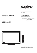
Reviews: