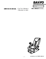
Sanyo HEC-DR5000, Service Manual
The Sanyo HEC-DR5000 Service Manual is your go-to resource for seamless operation and troubleshooting of this cutting-edge device. Easily download this comprehensive manual for free from our website, enabling you to harness the full potential of your Sanyo HEC-DR5000 without any hassle.
Share
Download


Reviews:
No comments
Related manuals for HEC-DR5000

4
Brand: Venen Engel Pages: 22

700
Brand: Katana Pages: 38
iJoy-1ST
Brand: Interactive Health Pages: 8
EP-MA70
Brand: Panasonic Pages: 13
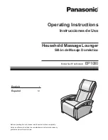
EP1080
Brand: Panasonic Pages: 18
EP1273 - MASSAGE LOUNGER
Brand: Panasonic Pages: 26
Real Pro Ultra EP30004
Brand: Panasonic Pages: 49
EP-MA73
Brand: Panasonic Pages: 58
EP30006KU - Real Pro Ultra Massage Chair
Brand: Panasonic Pages: 50

Pro
Brand: U-gym Pages: 8
X Rocker
Brand: Ace Bayou Pages: 6
AC-2000
Brand: Daga Pages: 32
RM-500
Brand: Daga Pages: 20
evero V4
Brand: HABYS Pages: 20
PRESTIGE-REH
Brand: HABYS Pages: 12
6036
Brand: OBH Nordica Pages: 14

Foot Spa
Brand: Lanaform Pages: 36
Full Mass
Brand: Lanaform Pages: 27


