background image

MODEL

Power source

Power consumption

Rated time

Personal sensor course

Automatic course

Kneading rate

Tap rate

Tap range

Back stretch settings

Vertical motion rate

Massage sphere vertical reach
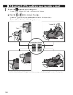
Reclining angle

Leg massage

Roller rotation

Timer

Dimensions (W x D x H)

Weight

HEC-DR21

AC 110 V 60Hz

165 W

30 minutes

Recovery / Relax

Four (neck / shoulders, upper torso, lower back, legs)

Approx. 16,22,30 pulses/min. (3 speeds)

Approx. 300,480,600 times/min. (3 positions)

Approx. 70,100,130mm (3 positions)

Approx. 70,100,130mm (3 positions)

Approx. 30sec./up-and-down cycle

Approx. 635mm (straight line)

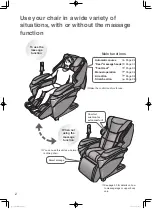
Back: approx. 120-170 degrees,  Leg: approx. 0-100 degrees

Rotating roller (Manual course: approx. 15 min., Automatic course: approx. 12 min.)

Higher speed: 100 times/min., Lower speed: 70 times/min.

Approx. 13 min. (Automatic Sensor course)

Approx. 12 min. (Automatic course)

Approx. 15 min. (Manual course)

Approx. 670 x 1,000 x 1,050 mm (When footrest is stored)

Approx. 670 x 1,550 x 550 mm (When footrest is in horizontal position)

Approx. 670 x 1,700 x 550 mm (When footrest is fully opened)

Approx. 55 kg


- 1 -

FILE No.

SERVICE MANUAL

Massage chair

HEC-DR21


(TAIWAN)

PRODUCT CODE NO.

  1 - 383  206  51  ( K )

  1 - 383  206  52  ( H )

REFERENCE NO.

 SM6510406-00

Summary of Contents for HEC-DR21

Page 1: ...Approx 70 100 130mm 3 positions Approx 30sec up and down cycle Approx 635mm straight line Back approx 120 170 degrees Leg approx 0 100 degrees Rotating roller Manual course approx 15 min Automatic course approx 12 min Higher speed 100 times min Lower speed 70 times min Approx 13 min Automatic Sensor course Approx 12 min Automatic course Approx 15 min Manual course Approx 670 x 1 000 x 1 050 mm Whe...

Page 2: ... elevating motor rotation Leg motor load detection Reclining backrest limit detection Reclining footrest limit detection Remote control operation and display Body contour detection coil Top end position detection of back massage section microswitch Rotation detection of massaging motor Hall IC IC 202 Detection of massaging arm home position Hall IC IC 201 Rotation detection of tapping motor Hall I...

Page 3: ...it Switch Reactor Reactor Leg Roller Switch Switch Motor Leg Roller Motor Switch Transfomer Transfomer Fuse 250V 4A Motor Printed board UP DOW Pulse Printed board Foot Rest Motor Elevation Printed board Sensor A Printed board Sensor B Printed board Indication Reclining Motor Back Rest Reclining Motor Leg Rest Printed board Main Printed board Pulse Printed board Relay Sensor B Printed board Control...

Page 4: ... Elevation Switch Fuse Transfomer Reactor Switch UP Reclining motor Back rest Reclining motor Leg rest Switch DOW Switch UP Switch DOW Limit switch Motor Leg roller Printed board Foot rest Printed board Shape Printed board UP DOW pulse Printed board Pulse Printed board Main Printed board Relay 4 Circuit Diagram HEC DR21 TAIWAN ...

Page 5: ...Printed board Control Printed board Indication Printed board Sensor A Printed board Sensor B Sensor B 5 Circuit Diagram HEC DR21 TAIWAN ...

Page 6: ... increase 4 In the case of pains perspiration rate greatly increases and number of pulses tends to increase Stiffness feeling is indicated by three colors green relax orange normal red stiffness feeling pains The body contour sensor judges the body contour shoulder position by changes of angles of massage arms Sensors consist of coils and iron cores detect displacement of reactance and convert int...

Page 7: ...completion of detection massage a buzzer comes on and massage of the course chosen takes place 6 Based on stiffness feeling judged in four stages by detection massage massage suited for stiffness feeling is carried out for about 10minutes by varying speed and time with respect to standard action of each course When Relax course is chosen Each massage at portions with stiffness feeling is carried o...

Page 8: ... via the driving belt whereby the massage unit is moved upward and downward This motor rotates clockwise and counterclockwise to thereby move the massage unit upward and downward Tapping massaging You can enjoy the good comfort that you can not do by hand tapping massage by starting both the tapping motor and the massage motor simultaneously I shaped tapping Z shaped massaging Massaging same porti...

Page 9: ...4 The connection confirmation of Printed board main CN13 and Printed board relay CN201 and CN202 5 The connection confirmation of Printed board pulse CN301 6 Check the Printed board pulse IC301 for inclination 7 The magnet check for the TATAKI detection Replace the current fuse Check the power switch and power cord and transfomer for normal conductivity and replace them if necessary upon check Rep...

Page 10: ...out the CN18 connector and check turning on confirmation of the motor side No1 to No2 pin and No3 to No4 pin Each connector insertion Each connector insertion If output from the both Replace the elevation motor If no output Replace the Printed board main or the elevation motor Each connector insertion Replace the limit switch Correct the tilted condition Replace the Printed board UP DOW Pulse Moun...

Page 11: ...f body contour sensor of the following section Check connections of substrate perspiration sensor CN951 and electrode cord Replace substrate perspiration sensor remote control main Check connection of substrate remote control main CN604 Replace substrate pulse and temperature sensors Replace substrate main Leg roller motor overcurrent Body contour sensor trouble Stiffness detecting sensor measurem...

Page 12: ...emperature sensor When temperature is about 17 or lower LED Ease goes on When temperature is over about 17 LED Ease goes out Pulse sensor Attach a finger to sensor by the side LED Recovery from fatigue blinks リクライニング Red s lighting up Skin temperature Pulse sensor Perspiration sensorLED Skin temperature sensorLED Red s lighting up Red s lighting up Presses Red s lighting up Red s lighting up Red s...

Page 13: ...TREST Photo 3 2 Detach PRINTED BOAD ASS Y FOOTREST Photo 3 3 Replacement of power switch section 1 Disconnect connector CN1 connected to PRINTED BOAD ASS Y MAIN Photo 2 2 Unscrew two CASE SWITCH BOX set screws and detach power supply switch section Photo 1 3 Open fuse case of current fuses and take out current fuses Photo 4 4 Unscrew two switch holder set screws and detach switch holder Photo 4 5 ...

Page 14: ... ASS Y MAIN 2 Detach bushing of remote control cord and remove remote control section 3 Unscrew five remote control case set screws and open remote control case vertically Photo 5 4 Unscrew one PRINTED BOAD ASS Y REMOTE CONTORL set screw and disconnect connector of CONNECTOR ASS Y Photo 6 5 Unscrew all the sensor set screws and remove PRINTED BOAD ASS Y SENSOR A SENSOR B Photo 6 COUTION LAVEL REMO...

Page 15: ... Photo 11 4 Unscrew two STAY A MOTOR T set screws and remove tapping motor section Photo 11 5 Remove PULLEY TM from tapping motor shaft and unscrew three tapping motor set screws Photo 11 Precautions for Assembly Securely fix STAY A with two STAY A set screws so that holes of frame coincide with those of STAY A MOTOR T see round section of Photo 12 Photo 12 Adjust and mount PULLEY TM so that groov...

Page 16: ...Replacement of gear box section 1 Detach massaging belt Photo 15 2 Unscrew two STAY HARNESS set screw and remove STAY HARNESS Photo 15 3 Unscrew one HOLDER MAGNET WIDTH set screw and detach HOLDER MAGNET WIDTH from shaft Photo 15 4 Remove RING C 13 from shaft Photo 15 5 Slightly unscrew four SAHFT M set screws on the right Photo 13 6 Unscrew four GEAR BOX ASS Y section fixing screws and detach GEA...

Page 17: ...and detach switch Photo 18 14 How to remove backrest section 1 Turn off power switch of main body with massage unit moved to the position of Photo 19 by adjusting UP DOWN by the use of remote control 2 Unscrew five BACK REST ASS Y set screws and remove BACK REST ASS Y Photo 19 15 Replacement of right and left arm section 1 Remove arm HELICAL SPRING Photo 20 2 Unscrew right arm fixing nut and detac...

Page 18: ...INN ASS Y Photo 22 18 Replacement of SHAFT ASS Y section 1 Unscrew two NUT PLASTIC NUT set screws Photo 23 2 Unscrew two HOLDER ROLLING SHAFT UP set screws remove HOLDER ROLLING SHAFT UP and remove the massaging section upwards Photo 23 19 Replacement of reclining section 1 Disconnect lead wires of each LINEAR ACTUATOR ASS Y 2 Since each LINEAR ACTUATOR ASS Y is fixed at two placed on both sides d...

Page 19: ...R UPPER Photo 27 4 Disconnect cords of MOTOR GEAR BOX ASS Y Photo 27 5 With ROLLER STAY ASS Y RIGHT LEFT suspended en block remove ROLLER STAY ASS Y LEFT from shaft of ROLLER STAY ASS Y LEFT Photo 27 6 Pull out SPRING PIN of MOTOR GEAR BOX ASS Y shaft Photo 28 7 Unscrew three MOTOR GEAR BOX ASS Y set screws and remove MOTOR GEAR BOX ASS Y Photo 28 Photo 25 Photo 26 FOOT REST COVER A Fasteners FOOT...

Page 20: ...ew three fixing screws to remove the transformer cover Photo 28 2 Unscrew fixing screws to remove the folder and pull out a connector 3 Unscrew fixing screws to remove the transformer Photo 30 20 SANYO Electric Co Ltd Osaka Japan Replacement Procedure HEC DR21 TAIWAN Oct 2002 Printed in Japan ...

Reviews: