

Summary of Contents for DVD1451U
Page 1: ...GB SERVICE MANUAL DVD1451U MPEG4 PLAYER SERVICE MANUAL ...
Page 9: ... Pinout Diagram 8 ...
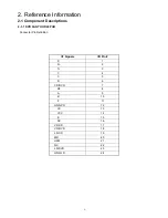
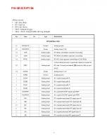
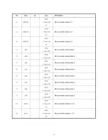
Page 10: ...PIN DESCRIPTON 9 ...
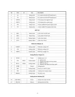
Page 11: ... 10 ...
Page 12: ... 11 ...
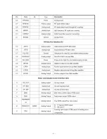
Page 13: ... 12 ...
Page 14: ... 13 ...
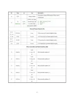
Page 15: ... 14 ...
Page 16: ... 15 ...
Page 17: ... 16 ...
Page 18: ... 17 ...
Page 19: ... 18 ...
Page 20: ... 19 ...
Page 21: ... 20 ...
Page 22: ... 21 ...
Page 25: ... 24 ...
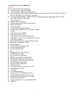
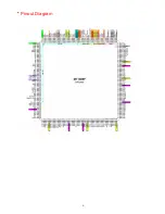
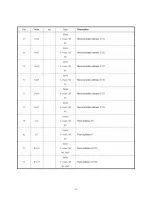
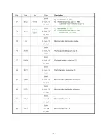
Page 27: ...Pin Configuration 26 ...
Page 33: ... 32 6 Disassembly and Reassembly ...
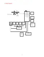
Page 35: ... 34 8 Block Diagram ...
Page 39: ......


