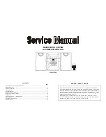
background image

FILE NO.

Service Manual

Micro Component System

DC-DA70

(AU)

(PA)

PRODUCT CODE No.
129 573 04 (AU)
129 573 05 (PA)

REFERENCE No. 

SM

5810135

SPECIFICATIONS

General
Output power ......................... 4 W x 2 (at 4 ohms, 10% distortion)
Outputs .................................. SPEAKERS : 4 ohms

PHONES : 8 - 32 ohms

Power requirements ............... AC 230 - 240 V, 50 Hz (AU)

      AC 110-120V/220-240V,
      50/60Hz (PA)

Power consumption ............... 19 W
Dimensions (W x H x D) ........ Approx. 140 x 210 x 200 mm
Weight .................................... Approx. 2.2 kg

Speaker system
Type ....................................... Full range bass reflex
Drivers ................................... 10 cm cone type
Maximum
   power-handling capacity ..... 6 W (peak)
Nominal impedance ............... 4 ohms
Dimensions (W x H x D) ........ Approx. 140 x 210 x 184 mm
Weight .................................... Approx. 1.2 kg (per speaker)

Specifications subject to change without notice.

Tuner
Reception frequency .............. FM : 87.5 - 108.0 MHz

AM : 522 - 1710 kHz(9KHz step)

520 - 1710 kHz(10KHz step)

  CD player

Channels ................................ 2-channel stereo
Sampling frequency ............... 44.1 kHz
Pick-up ................................... Optical 3-beam

semiconductor laser

Wave length ........................... 790 nm
Wow and Flutter ..................... Below measurable limits

Cassette deck section
Track system ......................... 4-track, 2-channel stereo
Frequency response .............. 80 Hz - 15kHz
Signal to noise ratio ............... 40 dB
Wow and Flutter ..................... 0.15% (WRMS)
Fast forward / Rewind time .... Approx. 110 sec. (C-60)

PA : This service manual consists of "DC-DA70U" (Main unit : 129 572 05)

         and "SX-DA70" (Speaker system : 165 006 00).

 AU : This service manual consists of "DC-DA70U" (Main unit : 129 572 04)

         and "SX-DA70" (Speaker system : 165 006 00).

Summary of Contents for DC-DA70

Page 1: ...rox 140 x 210 x 184 mm Weight Approx 1 2 kg per speaker Specifications subject to change without notice Tuner Reception frequency FM 87 5 108 0 MHz AM 522 1710 kHz 9KHz step 520 1710 kHz 10KHz step CD player Channels 2 channel stereo Sampling frequency 44 1 kHz Pick up Optical 3 beam semiconductor laser Wave length 790 nm Wow and Flutter Below measurable limits Cassette deck section Track system 4...

Page 2: ...ITETTAESSA OLET ALTTIINA NÄKYMÄTTÖMÄLLE LASERSÄTEILYLLE ÄLÄ KATSO SÄTEESEEN CD PICK UP MAINTENANCE About pick up Optical lens Cleaning Clean a lens with swab of the cotton which moistened it with alcohol cleaning paper or cleaning disc appointed Specified cleaning disc LC 1 Part code 645 026 1961 manufactured by SANYO Show a clean procedure in the following in reference by swab of cotton 1 Cotton ...

Page 3: ...ion after work is completed b Adjusting head azimuth 1 Load a test tape VTT 738 etc 10kHz for azimuth adjustment 2 Press the PLAY button 3 Use a cross tip screwdriver to turn the screw for normal azimuth adjustment so that the left and right outputs are maximized at the same phase during normal playback 4 Press the STOP button d Replacing the motor 1 2 3 4 4 MOTOR SPEED ADJUSTMENT c Adjusting moto...

Page 4: ...1 3 22pin TP22 TP23 T2002 IC211 3 22pin TP22 TP23 is 0 0 0 05V is 0 0 0 05V Cover Voltage Alignment Low 87 5MHZ 1 00 0 5V Check Only L2002 Check Only High 108 0MHZ 6 20 0 1V Check Only Tracking Voltage Alignment Low 90 0MHZ Maximum Confirm S N 30dB High 106 0MHZ AM Ant IRE LOOP ANT Modulation frequency 1kHz Modulation 30 Item Frequency Alignment P a r t s Remark IF Alignment 450kHz at 999kHz Maxim...

Page 5: ...12 13 3 4 2 5 6 7 8 9 10 11 19 20 16 18 31 26 17 25 23 22 21 15 24 14 27 28 Y15 Y15 Y06 Y06 Y07 Y13 Y12 Y14 Y14 Y08 Y08 Y08 Y11 Y03 29 Y13 Y14 Y04 Y10 Y09 Y09 Y05 Y05 Y16 Y16 Y10 Y07 Y13 Y01 Y01 30 30 73 57 72 75 74 52 71 76 58 55 56 51 ...

Page 6: ...A PAUSE 11 614 307 2270 MOUNTING DECK KNOB 12 614 307 2263 LID CASSETTE 13 614 308 5058 SPRING DOOR DECK 14 614 308 1197 ASSY CABINET REAR AU 14 614 308 1203 ASSY CABINET REAR PA 15 614 307 2003 BUTTON POWER 1 KEY 16 614 307 2010 BUTTON FUNCTION 10 KEYS 17 614 307 2027 BUTTON CD OPEN 1 KEY 18 614 307 8784 LEVER 19 614 307 8722 BUTTON PUSH 1 KEY 20 614 307 2034 BUTTON BASS 1 KEY 21 614 311 7872 ASS...

Page 7: ...TR 2SA608 G SPA or 405 006 1806 TR 2SA933S R or 405 006 1905 TR 2SA933S S or 405 004 4601 TR 2SA608 F SPA or 405 143 6504 TR KTA1267 GR Q4851 405 151 4400 TR KTD1303 or 405 021 0204 TR 2SD1012 F SPA or 405 021 0600 TR 2SD1012 G SPA or 405 033 6706 TR 2SD1468S R or 405 033 6805 TR 2SD1468S S Q4902 405 017 9709 TR 2SC3330 U or 405 017 9600 TR 2SC3330 T or 405 011 8609 TR 2SC1740S S or 405 143 8706 T...

Page 8: ...01 645 009 8871 SWITCH PUSH 2P 2T POWERSW S4905 645 040 8137 SWITCH SLIDE 2P 2TX1 BEAT CCL S4950 645 038 7586 SWITCH PUSH R PSW SA401 411 021 6405 SCR S TPG BIN 3X8 SA402 411 021 6405 SCR S TPG BIN 3X8 614 125 0236 CUSHION FOR W207 FRONT P W BOARD ASSY REF NO PART NO DESCRIPTION 72 614 310 4100 ASSY PWB FRONT Only Initial BR601 614 307 2164 HOLDER LCD C6200 403 259 0508 NP ELECT 1U M 50V CN601 645...

Page 9: ...10W R1454 401 038 9001 MT GLAZE 680 JA 1 10W R1455 401 038 9308 MT GLAZE 68K JA 1 10W R1456 401 037 6704 MT GLAZE 1 2K JA 1 10W R1462 401 038 7601 MT GLAZE 560 JA 1 10W R1463 401 038 7601 MT GLAZE 560 JA 1 10W R1464 401 037 5400 MT GLAZE 1K JA 1 10W R1465 401 038 7601 MT GLAZE 560 JA 1 10W R1472 401 038 6406 MT GLAZE 4 7K JA 1 10W R1473 401 037 5707 MT GLAZE 100K JA 1 10W R1475 401 038 7601 MT GLA...

Page 10: ...T GLAZE 10K JA 1 10W R2105 401 037 5608 MT GLAZE 10K JA 1 10W R2106 401 038 2101 MT GLAZE 2 7K JA 1 10W R2107 401 038 9209 MT GLAZE 6 8K JA 1 10W R2113 401 037 5608 MT GLAZE 10K JA 1 10W R2117 401 039 0601 MT GLAZE 820K JA 1 10W R2119 401 038 0800 MT GLAZE 22K JA 1 10W R2126 401 037 6902 MT GLAZE 120K JA 1 10W R2127 401 038 6406 MT GLAZE 4 7K JA 1 10W R2128 401 038 3801 MT GLAZE 330K JA 1 10W R212...

Page 11: ... 009 1766 RF BELT TM05 645 033 3415 MAIN BELT TM06 614 304 1467 ASSY MOTOR TM06 TM05 TM04 TM02 TM01 TM03 CD MECHANISM CDDA11 SASH Only Initial REF NO PART NO DESCRIPTION PM01 620 021 8436 PLUG 6P PM02 620 233 0853 ASSY MOTOR BASE CHASSIS ASSY PM03 620 236 3776 COVER GEAR PM04 620 230 8753 GEAR MIDDLE RELAY GEAR PM05 620 230 8760 GEAR DRIVE PM06 620 231 0596 SHAFT SLIDE PICK RAIL PM07 620 233 0860 ...

Page 12: ...se Input PICK INSIDE Input REMOCON Input BAND Output AUDIO MUTE Output Compalsion MONO Output FUNCTION Input Output CHATTERING TIME 40MS STEREO Input CHATTERING TIME 40MS SYNC REC Input CHATTERING TIME 40MS Power supply SD Input Display SEGMENT Output VOL IC Control Output Operating KEY Input Destination Input BASS X LID SW Input CHATTERING TIME 40MS BACK UP MODE Control Outpu Power supply Ground ...

Page 13: ... LOGICK SPINDLE SERVO SLED SERVO g IC412 TA8229K AF Main Amplifier 1 2 3 4 5 6 7 8 9 10 11 12 13 14 15 16 17 18 19 20 21 22 23 24 Vcc Vref VIN4 VG4 Vo8 Vo7 GND Vo6 Vo5 VG3 VIN3 CD RES Vcc Mute VIN1 VG1 Vo1 Vo2 GND Vo3 Vo4 VG2 VIN2 Reg OUT Reg IN Vcc 11k 11k 11k 11k Level Sift BTL Driver BTL Driver Level Sift RESET Regulator Level Sift BTL Driver Level Sift BTL Driver IC411 LC75392 Pick up Actuator...

Page 14: ... 28 29 48 60 61 46 52 45 44 43 39 41 42 40 37 35 38 36 34 31 30 9 21 6 4 3 5 7 2 59 64 11 32 33 62 8 23 Slice level Control Subcode Dxract QCRC Syncrnous Detect EFM Demodulation VCO Clock Oscillator Clock Control X tal Root Timing Generator RAM Address Generatorl 2K 8bit RAM Billingual Digital Out General Ports Digital Attenuator Quadruple Over Sampling Digital Filter Interpolalation Mute C1 C2 Er...

Page 15: ... 15 14 SCHEMATIC DIAGRAM TUNER AU This is a basic schematic diagram ...

Page 16: ... 19 18 SCHEMATIC DIAGRAM TUNER PA This is a basic schematic diagram ...

Page 17: ... 23 22 SCHEMATIC DIAGRAM AMP AU This is a basic schematic diagram ...

Page 18: ... 27 26 SCHEMATIC DIAGRAM AMP PA This is a basic schematic diagram ...

Page 19: ... 31 30 SCHEMATIC DIAGRAM FRONT This is a basic schematic diagram ...

Page 20: ...001 PA This schematic diagram is for units with smaller serial number than M0403001 AU M0402001 PA Please refer to the schematic diagram on the page 34 35 for the units with serial number M0403001 AU M0402001 PA onward Please see the wiring diagram on the page 38 This is a basic schematic diagram ...

Page 21: ...01 PA This schematic diagram is for units with serial number M0403001 AU M0402001 PA onward Please refer to the schematic diagram on the page 32 33 for the units with smaller serial number than M0403001 AU M0402001 PA Please see the wiring diagram on the page 36 37 This is a basic schematic diagram ...

Page 22: ...s with serial number M0403001 AU M0402001 PA This wiring diagram is for units with smaller serial number than M0403001 AU M0402001 PA Please refer to the wiring diagram on the page 36 37 for the units with the serial number M0403001 AU M0402001 PA onward ...

Page 23: ... 39 WIRING DIAGRAM LED POWER LED P W BOARD POWER TRANSFORMER P W BOARD This wiring diagram is for AU version This wiring diagram is for PA version ...

Page 24: ...8 8 0 1 0 6 3 9 0 3 9 0 6 0 IC411 LC75392 UNIT V Pin No 1 2 3 4 5 6 7 8 9 1 0 1 1 1 2 1 3 1 4 1 5 1 6 1 7 1 8 1 9 2 0 2 1 2 2 Voltage 7 6 1 63 1 65 1 64 1 64 1 63 1 64 1 63 1 64 1 64 1 64 1 64 8 53 0 04 0 04 0 04 0 1 64 1 64 1 64 1 64 1 64 Pin No 2 3 2 4 2 5 2 6 2 7 2 8 2 9 3 0 Voltage 1 64 1 64 1 64 1 64 1 64 1 71 1 63 7 6 IC412 TA8229K UNIT V Pin No 1 2 3 4 5 6 7 8 9 1 0 1 1 1 2 1 3 1 4 1 5 Volt...

Page 25: ...XF IC412 TA8229K HEAD PHONE RIGHT SPEAKER LEFT SPEAKER CN421 PICK UP A C B D E F 1 2 3 4 41 10 5V IC101 LA9241M IC102 LC78622NE 37 40 L R L R RF 13 14 21 1 1 IC211 LA1844M IC201 LA1186N EF FILTER RF BPF FM ANT AM LOOP R P P R P R P P R L R L R L R R P R HEAD P R HEAD HF DSC 6 TUNER SECTION CD SECTION AMP SECTION 12 10 2 6 S4950 3 S4950 4 S4950 6 S4950 5 S4950 1 ...

Page 26: ... W B LED P W B BOARD TO BOARD LCD60 CN441 2P CN406 4P CN491 12P CN421 PHONES CN490 8P CN402 2P CN401 2P CN422 2P CN601 12P CN603 17P CN602 2P CN122 8P CN111 15P 15P CN113 6P 6P CN201 CN203 1P CN202 17P CN405 4P FU401 T2A L 250V BK RE BR P T POWER SUPPLY P W B AMP P W B TUNER P W B AM LOOP ANT FM ANT BL AC IN 230 240V 50Hz AU 110 120V 220 240V 50 60Hz PA ...

Page 27: ...M1 7A 7B 6A 6B JAZZ PLAY 5 AM COM2 COM2 7F 7G 7C 6F 6G 6C MHZ MEM FM COM3 COM3 7E 7D CH 6E 6D TR KHZ LW MW PAD NO 13 14 15 16 17 18 19 20 21 22 23 24 25 COM1 4A 4B 4H 3A 3B 3H 2A 2B 2H PCP 1A 1B 1H COM2 4F 4G 4C 3F 3G 3C 2F 2G 2C ROCK 1F 1G 1C COM3 4E 4D REP 3E 3D PS 2E 2D MONO CLASSIC 1E 1D ST 1H 2H 3H 4H A J F I K B G M L N H E C D ...

Page 28: ... 17 16 WIRING DIAGRAM TUNER AU ...

Page 29: ... 21 20 WIRING DIAGRAM TUNER PA ...

Page 30: ... 25 24 WIRING DIAGRAM AMP AU ...

Page 31: ... 29 28 WIRING DIAGRAM AMP PA ...

Page 32: ...e units with serial number M0403001 AU M0402001 PA This wiring diagram is for units with serial number M0403001 AU M0402001 PA onward Please refer to the wiring diagram on the page 38 for the units with the smaller serial number than M0403001 AU M0402001 PA ...

Reviews: