background image

Service Manual

FILE NO.

REFERENCE No. 

SM

5810232

PRODUCT CODE No.
164 073 07 CWM-240/MX
164 073 02 MCD-Z128F/XE
164 073 06 MCD-Z128F/AU
164 073 00 MCD-Z130F/XE
164 073 01 MCD-Z130/CA
164 073 03 MCD-Z130F/AU
164 073 04 MCD-Z130F/PA
164 073 30 MCD-Z130L/UK
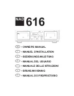
CD Portable Radio
Cassette Recorder

CWM-240 

   (MX)

MCD-Z128 series
MCD-Z130 series

SPECIFICATIONS

(CASSETTE SECTION)

Recording System ................. 4-track, 2-channel stereo

Erasing System ..................... Magnet erase

Tape speed ........................... 4.75 cm/sec.

Fast forward and

      Rewind time .................... Approx. 110 sec. (C-60 tape)

 Frequency range .................. 80 - 12,000 Hz (Normal tape)

(CD PLAYER SECTION)

Channels ............................... 2 channels stereo

Wow & Flutter ........................ Below measurable limits

Sampling frequency .............. 44.1 kHz

Quantization .......................... 16 bits linear/ch

Pickup light source ................ Semi-conductor laser

Pickup wave length ............... 790 nm

Laser output .......................... Continuous wave max. 0.6 mW

(RADIO SECTION)

Tuning range ......................... FM : 87.5 - 108 MHz

AM : 526.5  - 1,606.5 kHz

LM : 148.5  - 283.4 kHz(130L Only)

(GENERAL SECTION)

Power output ......................... 2W/ch (DC max)

Speaker ................................. 10 cm x 2

Terminal impedance ............. PHONES : 32 ohms

Power source ........................ AC : 120V, 60Hz (MX,CA)

: 230V, 50Hz (XE,UK)

: 230-240V, 50Hz (AU)

: 110-120/220-240V, 50/60Hz (PA)

DC : 12 V (8 "R20/D" batteries)

Dimensions ........................... 472 (W) x 158 (H) x 252 (D) mm

Weight (approx.) .................... 3.0 kg (Not including batteries)

Specifications subject to change without notice.

CWM-240
MCD-Z130 Series

MCD-Z128 Series

Summary of Contents for CWM-240

Page 1: ...Hz Normal tape CD PLAYER SECTION Channels 2 channels stereo Wow Flutter Below measurable limits Sampling frequency 44 1 kHz Quantization 16 bits linear ch Pickup light source Semi conductor laser Pickup wave length 790 nm Laser output Continuous wave max 0 6 mW RADIO SECTION Tuning range FM 87 5 108 MHz AM 526 5 1 606 5 kHz LM 148 5 283 4 kHz 130L Only GENERAL SECTION Power output 2W ch DC max Spe...

Page 2: ...ZEN VARO AVATTAESSA JA SUOJALUKITUS OHITETTAESSA OLET ALTTIINA NÄKYMÄTTÖMÄLLE LASERSÄTEILYLLE ÄLÄ KATSO SÄTEESEEN AU XE PA Pickup that emits a laser beam is used on this CD section CAUTION USE OF CONTROLS OR ADJUSTMENTS OR PERFORMANCE OF PROCEDURES OTHER THAN THOSE SPECIFIED HEREIN MAY RESULT IN HAZARDOUS RADIATION EXPOSURE LASER OUTPUT 0 6 mW Max CW WAVE LENGTH 790 nm LASER BEAM SAFETY PRECAUTION...

Page 3: ...01 2 pin E Connect FM SG to JP105 H D102 E Connect FM SG to JP105 H D102 E Output Connect VTVM to generator to 19 IC101 H and C104 E Connect VTVM to speaker terminals Connect VTVM to speaker terminals Adjusting Circuit IF Tuning coverage Tracking SG Frequency 10 7 MHz 87 30 MHz 108 75 MHz 90 0 MHz 106 0 KMz Position of Tuning dial Low Low end High end 90 0 MHz 106 0 MHz VTVM Oscilloscope Max Max S...

Page 4: ...6 LW COIL CT105 Connections a AM Adjustment Band switch MW Input Connect sweep generator to IC101 1 pin H IC101 2 pin E Connect FM SG to JP105 H D102 E Connect FM SG to JP105 H D102 E Output Connect VTVM to generator to 19 IC101 H and C104 E Connect VTVM to speaker terminals Connect VTVM to speaker terminals Adjusting Circuit IF Tuning coverage Tracking SG Frequency 10 7 MHz 87 30 MHz 108 75 MHz 9...

Page 5: ... secure the azimuth adjustment screw 4 MOTOR SPEED ADJUSTMENT 1 Insert the test tape TCC 119 etc 3 000 Hz 2 Press the PLAY button 3 Use a flat tip screwdriver to turn the SVR located inside the rear of the motor to adjust SVR so that the frequency counter become 3 000 Hz 5 CHECKING THE MECHANISM TORQUES AND TENSION Clean the head capstan and pinch roller before making any measurement Measurement T...

Page 6: ...CN202 5P CN204 5P CN101 5P DC12V 15P RECTIFIER P W B CD MAIN AMP P W B DISPLAY P W B TUNER P W B REC SW P W B CD SWITCH P T BATTERY AC IN FM ROD ANT RED ORANGE BROWN YELLOW YELLOW BLACK AC IN 1 AC IN 3 GND DC 0 DC 1 L CH SPEAKER R CH SPEAKER YELLOW BLACK YELLOW YELLOW BLACK MOTOR SWITCH R P HEAD M TAPE DECK MECHANISUM BLACK LED ORANGE LH RH GND BS FM ANT WIRING CONNECTION ...

Page 7: ...Y12 Y12 Y13 Y13 Y14 Y16 Y18 Y17 Y20 Y20 Y20 Y22 Y22 Y23 Y20 Y20 Y01 51 Y02 Y02 7 Y02 Y03 Y03 7 7 Y02 7 6 6 Y01 3 10 11 12 14 15 15 25 16 17 18 21 23 26 27 28 71 72 73 74 29 29 30 32 33 34 35 36 57 40 41 31 24 13 52 54 53 55 56 75 81 43 42 MCD Z130F XE MT 2001 04 ...

Page 8: ...ET 128 AU 130 PA 128 XE 5 645 051 6344 ASSY CABINET 240 MX 130 CA 130 UK 130 XE 130 AU 6 645 033 4252 ASSY GEAR S905 7 645 033 0360 SPK CLIP 9 645 051 6863 KNOB CASS PAUSE 10 645 051 6870 KNOB CASS STOP EJECT 11 645 051 6887 KNOB CASS FFWD 12 645 051 6894 KNOB CASS REWIND 13 645 051 6900 KNOB CASS PLAY 14 645 051 6917 KNOB CASS RECORD 15 645 051 6948 CTL BD HOLDER FOR DISPLAY 16 645 051 6849 KNOB ...

Page 9: ... 1U M 50V C0903 403 057 3800 POLYESTER 0 1U M 50V C0904 403 062 1105 POLYESTER 0 047U M 50V C0905 403 060 6904 POLYESTER 3300P M 50V C0908 403 060 8908 POLYESTER 0 033U M 50V C0909 403 057 3800 POLYESTER 0 1U M 50V C0911 403 062 1105 POLYESTER 0 047U M 50V C0912 403 063 0800 POLYESTER 6800P M 50V C0928 403 060 8908 POLYESTER 0 033U M 50V C0930 403 057 1202 POLYESTER 0 01U M 50V C0932 403 060 8908 ...

Page 10: ... 0708 POLYESTER 0 018U M 50V CF102 645 051 6450 CERAMIC FILTER CF103 645 027 0291 CERAMIC FILTER Except UK XE CF103 645 041 9966 CERAMIC FILTER UK XE CF104 645 051 6467 BAND PASS FILTER CN101 645 051 6535 5P HEADER V TYPE CT105 645 033 4771 TRIMMER 20PF UK CT106 645 033 4771 TRIMMER 20PF UK D0101 645 023 6099 DIODE 1N 4148 D0102 645 023 6099 DIODE 1N 4148 D0103 645 023 6082 DIODE 1S 2638 AFC D0104...

Page 11: ...Y MOTOR 1 2 3 4 5 6 7 8 9 10 11 12 24 23 22 21 20 19 18 17 16 15 14 13 FM RF AM RF AM MIX FM MIX FM OSC AM OSC REG Vcc1 Vcc2 GND2 GND1 DECODER PHASE COMP PILOT DET TRIG ST SW VCO DET DET AM IF S METER FM IF AGC FF FF FF ST LED TUN LED IC BLOCK DIAGRAM DESCRIPTION IC101 LA1824 Tuner 28 27 26 25 24 23 22 21 20 19 18 17 16 15 1 2 3 4 5 6 7 8 9 10 11 12 13 14 Vcc Vcc DRIVER MUTE D BUF D BUF D BUF D BU...

Page 12: ... sled movement signal from microprocessor 30 SL Input pin for sled movement signal from microprocessor 31 OSC Pin for setting oscillating frequency 32 NC No connection No PIN NAME Function 33 SLOF Sled servo off control input pin 34 TGRF Pin for setting the function on off which function is tracking gain following to RF level 35 SP8 Switch control pin for spindle 8cm 12cm mode 36 EFBAL E F balance...

Page 13: ...ut terminal The pull up resister internal 29 DOUT Digital OUT output terminal EIAJ format 30 NC NC Being open 31 SEG8 The segment output 8 terminal The pull up resister internal 32 SEG7 The segment output 7 terminal The pull up resister internal No PIN NAME Function 33 SEG6 The segment output 6 terminal The pull up resister internal 34 SEG5 The segment output 5 terminal The pull up resister intern...

Page 14: ...o 1 2 3 4 5 6 7 8 9 10 11 12 13 14 15 16 Voltage 3 6 3 7 2 5 2 5 7 05 5 1 5 1 0 2 5 2 55 3 61 3 55 0 7 3 0 55 0 71 Pin No 17 18 19 20 21 22 23 24 25 26 27 28 Voltage 3 3 3 95 3 91 2 8 2 5 7 82 7 81 2 5 2 6 3 75 3 75 0 IC101 LA1824 RADIO MODE V Pin No 1 2 3 4 5 6 7 8 9 10 11 12 13 14 15 16 AM Voltage 1 27 1 27 4 96 4 9 4 9 0 4 9 0 0 1 27 1 26 0 6 4 9 0 0 1 3 FM Voltage 1 2 1 2 4 91 4 91 4 91 0 4 9 ...

Page 15: ...onents in which safety can be of special significance When replacing a component identified by use only the replacement parts designated or parts with the same ratings of resistance wattage or voltage that are designated in the parts list in this manual Leakage current or resistance measurements must be made to determine that exposed parts are acceptably insulated from the supply circuit before re...

Page 16: ...onents in which safety can be of special significance When replacing a component identified by use only the replacement parts designated or parts with the same ratings of resistance wattage or voltage that are designated in the parts list in this manual Leakage current or resistance measurements must be made to determine that exposed parts are acceptably insulated from the supply circuit before re...

Page 17: ...ents in which safety can be of special significance When replacing a component identified by use only the replacement parts designated or parts with the same ratings of resistance wattage or voltage that are designated in the parts list in this manual Leakage current or resistance measurements must be made to determine that exposed parts are acceptably insulated from the supply circuit before retu...

Page 18: ... 17 SCHEMATIC DIAGRAM CD for Z130 series ...

Page 19: ... 18 SCHEMATIC DIAGRAM CD for Z128 series ...

Page 20: ... 19 SCHEMATIC DIAGRAM TUNER for XE PA ...

Page 21: ... 20 SCHEMATIC DIAGRAM TUNER for UK ...

Page 22: ... 21 SCHEMATIC DIAGRAM TUNER for CA MX ...

Page 23: ... 22 SCHEMATIC DIAGRAM TUNER for AU ...

Page 24: ... 23 WIRING DIAGRAM CD MAIN ...

Page 25: ... 24 WIRING DIAGRAM TUNER for except UK ...

Page 26: ... 25 WIRING DIAGRAM TUNER FOR UK ...

Page 27: ... 26 WIRING DIAGRAM DISPLAY ...

Page 28: ...SANYO Electric Co Ltd Osaka Japan Aug 01 2850 BB Printed in Japan WIRING DIAGRAM RECTIFIER REC SW RECTIFIER REC SW ...

Reviews: