SERVICE MANUAL Colour Television
Product Code: 111358219
Original Version
Chassis Series: AC5-G1
C4VZ
FILE NO.
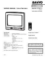
Model No. CP21KX2
(A)
Service Ref. No. CP21KX2-50
(Australia)
Give complete “SERVICE REF. NO.” for
parts order or servicing. It is shown on the
rating plate at the cabinet back of the unit.
This T.V. receiver will not work properly in
foreign countries where the television
transmission system and power source dif-
fer from the design specifications. Refer to
the specification table.
REFERENCE NO.
SM
5110601
0
7
1
4
8
5
2
3
6
9
P
▲
P
▼
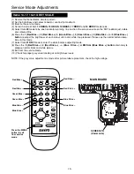
JXMYA
-/--
P
P
TV/AV
A B
CH SCAN
TIMER
MENU
PIC MODE
SWAP
BASS
SURROUND
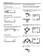
VIDEO
L-AUDIO-R
TV/AV MENU
CH
Specifications
Power Source . . . . . . . . . AC110-240V, 50Hz/60Hz.
Colour System . . . . . . . . PAL/NTSC4.43/NTSC/PAL-60Hz
Television System . . . . . . B/G, D/K, K’, I, M/M
Channel Coverage . . . . . VHF: 0-11, 5A (Aus.), 1-11(NZ),
E2-E12, R1-R12, K1-K9, A2-A13, J1-J12
UHF: 21-69, A14-A69, J13-J62
CATV: S1-S41, X, Y, Z, Z+1, Z+2
Video IF . . . . . . . . . . . . . . 38.0MHz
Aerial Input Impedance . . 75
Ω
Ext. Terminals
Video inputs: Phono jack
✕
2 (1Vp - p, 75
Ω)
Audio inputs: Phono jack(L/R)
✕
2(436mVrms, more than 40K
Ω)
Video monitor outputs: Phono jack
✕
1(1Vp - p, 75
Ω)
Audio monitor outputs: Phono jack (L/R)
✕
1(436mVrms, less than 600
Ω)
Sound Output (RMS) . . . . 5W + 5W
Speaker
. . . . . . . . . 6 cm
✕
12 cm
✕
2 pcs.
Dimensions
. . . . . . . . . 625 (W)
✕
461 (H)
✕
484 (D)mm
Weight
. . . . . . . . . approx. 21.2 Kg
Specifications subject to change without notice.
Summary of Contents for CP21KX2
Page 26: ... 26 ...
Page 27: ... 27 ...
Page 28: ...SANYO Electric Co Ltd A14800 Oct 04 30 BB Printed in Japan ...