background image

Summary of Contents for CLA-1380

Page 1: ...uit Description 36 Troubleshooting Guide 40 PRODUCT CODE No 178 585 93 Voltages of lC and Transistor 49 Block Diagram Handset 53 Schematic Diagram Handset 54 Wiring Diagram Main of Handset 56 Block Diagram Base Station 58 Wiring Diagram Control of Handset 60 Schematic Diagram Base Station 62 Wiring Diagram Control of Base Station 64 Wiring Diagram OHM 65 Wiring Diagram Main of Base Station 66 Sche...

Page 2: ...cessories yes base station 10 number 10 channel Manual scan 10 million 1 week yes yes yes yes yes yes handset and base station yes yes Local current with AC adaptor AC 230 240 V I 50 Hz DC9V Ni Cd battery 3 6 V 270 mAH 172 W x53 H x227 D mm 58 W x205 H x50 D mm 694 g without adaptor 265 g including batteries AC adaptor and plug adaptor Telephone line cord Wall mount Hanger Instruction manual Micro...

Page 3: ...tine by another cordless talephona If you hear a high pitched beep tone or no dial tone ths means that ths security ccda has been fost If this occurs reset the security coda ss de scribed onpagell If a power failure occurs or Hthe battmy is mplacad tha security We must ba reset Sea page 11 operating range The operating range may vary depencfhg on the operating condkions location and distancs betwe...

Page 4: ...oting guide on page 41 c After initial setup recharge the handset banery by placing it on the base station cradle whenever the BAIT LOW indmator hghts Replacement banery packs are available from an authorized Sanyo service center ReDlacemmt bafferv mck D BAIT LO mdcator nUkbOC SANYO 3N 2 70W Use of other brand or type baner es may cause serious damage or equipment maituntilons NOTE 6 When batterie...

Page 5: ...ve a noisy telephone exchange If the switch is not in the CPC OFF position your calls may ba disconnected prematurely ANSWER ONLY If you do not want massagas to ba raceivad and racordad sat the switch to the ANS ONLY peaiion The unil then plays your outgoing massage but doss not record iktcoming messages CPWANS ONLY switch 3 Mount tha basa station on the wall P l o k A Wall mount 2 hanger To socke...

Page 6: ...rely SW We 13 even if the RINGERsw tch s VOLUMEControl Musts mesouti levelfrcmU m base ho speaker Seepage10 BOTTOM VIEW J o ml e 3Pa Rmte AccessCodeNumber Label w w B a Dl Jno MEMORYButton 7 presstostore phOmnumb mrnmwycftomcda sl nwd onen nbr see page2 2 reJyt0tTsp9s lem REDIALIPBun Presstordld he Ih t umberd aledIfWI press my otier dmlmg button More pmsmg m bum t furcticiuasa pauseMton 3wp 228 2...

Page 7: ...hs desirad Iwation 3 Fully esfend ths antenna on the handset 4 Press the TALK button Make sure that you gaf a dial tons and the TALK indiitor fights 5 Make a call 6 Press the END button to ratum the handset to tha standby mcxte NOTE If the phone doss not work propw Iy chack the system connactiins and the oparatmg rangs If the BATT LOW indwator IS It charge the handset Saa page 8 1O CHANNEL ACCESS ...

Page 8: ...e station Auto Intercom 1 Hand8et Press the END buffon 2 Hand8et Prass tha INT button to page tha base stafiin The baae stafiin automatically switches to intercom mode 3 Handset and bna station Bagin intercom conversafiin 4 Handset When intenmn conversation is ovar press tha END bulton to swnch tfw intercom mode off INTERCOM From base statban 10 handset 1 Sa80daUcw Press tha PAGE NT bulton to page...

Page 9: ...n The message tape rewinds and a beep sounds After the message tape is erased the unit automafical fy returns to the auto answer retie NOTE If the end of tha rfwssage tap IS reached whtfa a message or memo IS being racorded the ANSWER ihdiiator flashes slowly and continuously If this happens you cannot perform AUTOMATIC PLAYBACK Before proceeding wth manual message playback press the STOP button a...

Page 10: ...es sage playback begins again To turn off ths answering system using ths hsrtdsat 1 Press the REMOTE button The REMOTE Indmtor hghts If no messsges have been recorded 3 bseps sound 2 Press O Immediately The unit turns oft automafiially H u REMOTE Indicator 0000 REMOTE 000 buiton indicator REMOTE CONTROL FROM ANOTHER TELEPHONE You can access your answering RemoteAcce8sCodeNumbu label system from an...

Page 11: ...6 rings the unit plays back your outgoing message and 3 beeps sound 3 Affer 3 beeps no sound IS mmm heard for approximately 10 seconds 4 Within these 10 seconds enter L ___ your remote access cwle The message taps rewinds and W pkl back At the end of the last message 3 beeps sound 5 After 3 beeps press 2 within 10 seconds 6 Hang up The message tapa rewinds and the unit automafiialiy resets to the ...

Page 12: ...ry to rstrieve your rmsssges from anotlmr telephons but nothing hsppen You may nothave entered the correctmmofe sccess code numb r You may nothave entersd the correctremote sccess cede or entered ti incomcfiy You may notbe usingTwchTotw telspiwne m the telephonedoes not producecontinuoustonas W 3 the dialingbulfonsare prsssed You may have entered yourmmcde accesscode beforethe beep that followsyou...

Page 13: ...n can affact tha oparation ranga Try sev eral l fiOns in your home or bush nass and pick the one that gives you tfw claarest signal to the handsI t Tummg around whik holding the handset may help you find tha bast position 3 INTERFERENCE Elacfrwmc circuits activate a relay to connsct the cordless telephone to your telephone line These elecfmnic citcuits oparate inthe radio fraquemy spectrum Wh e sa...

Page 14: ...P LID 1 Remove 4 bottom cabinet mounting screws 2 REMOVAL OF MAIN P W BOARD 1 Remove the antenna lead wire 2 Remove a MAIN P W Board mounting screw 3 REMOVAL OF MECHANISM 1 Remove 4 mechanism mounting screws 1 I 4 REMOVAL OF CONTROL P W BC ARD 1 Remove 6 CONTROL P W Board mounting screws 2 Remove the CONTROL P W Board as shown the figure d 13 ...

Page 15: ... I 2 HANDSET SECTION n I REMOVAL OF CABINET LJ The procedure for disassembly the handset is as follow 1 2 3 4 Remove the battery compartment lid 0 Remove the battery pack Remove a handle mounting screw Q While pressing the shaded area to release the hooks on both sides of the cabinet 0 gently open the bottom of the cabinet 0 While gently opening the handle lift and remove 0 6 PUSH y Jill I i n 600...

Page 16: ...ad wire and the P W Board Q 3 Remove the 3 connectors 4 Remove the antenna 3 REMOVAL OF CONTROL P W BOARD 1 Remove the 5 CONTROL P W Board mounting screws D 2 Taking care not to damage the TALK and BATT LOW LED s remove the control P W Board as shown in the figure Q 3 Remove the ringer switch on the control P W Board as shown in the figure 15 ...

Page 17: ...or speed 3kHz lOdB MC 30 Normal tape 2 Oscilloscope 3 AF VTVM 4 Frequency counter CLEANING THE HEADS To ensure continued high performance from the answering system clean the 5 Screwclriv er non metallic for adjustments head pinch roller and capstan periodically whenever dust or reddish brown oxide particles have accumulated Failure to do so may result in inferior sound qualify and inconsistent tap...

Page 18: ... 3kHz for azimuth RIP HEAD E HEAD Siili5 gi BLUE w adjustment Press the PLAY button HEAD AZIMUTH ADJ Use a cross tip screwdriver to turn the screw for azi muth adjustment so that the output is maximized After completion of the adjustment use thread lock TB 1 401 B to secure the azimuth adjustment screw 2 MOTOR REPLACEMENT AND SPEED ADJUSTMENT 1 MOTOR REPLACEMENT I I I 1 I 2 MOTOR SPEED ADJUSTMENT ...

Page 19: ...Hz 39 950 MHz 9 30 275 MHz 39 975 MHz 0 1o 30 300 MHz 40 000 MHz TEL BASE STATION 30 MHz BAND o I CONTROL TX 1 L 1 i I I I I I I 39 MHz BAND I RX I 1 L J MEASURING INSTRUCTIONS TOOLS 1 2 3 k 4 5 6 7 8 9 FM STANDARD SIGNAL GENERATOR MSG 2560B etc Frequency 100 kHz 110 MHz Modulation 2 5kHz Level 46dBP LINEAR DETECTOR FOR FM LD 460 etc RF VTVM or ELECTRONIC VOLTMETER ML 69A etc FREQUENCY COUNTER VP ...

Page 20: ...oitmeter and switch S101 to P152 P152 2 Set switch S101 to the TX position 2 Set switch S101 to the RX position 3 Adjust T253 TX so that the reading of the Digital 3 Adjust TI 52 RX so that the rdading of the Digital voltmeter is 1 8 V 0 2 V voltmeter is 1 8 V 0 2 V STEP CONDITION ADJUST ADJUST VALUE SPECIFICATION 1 TX VCO S101 TX SIDE T253 1 8V 1 820 2V 2 RX VCO S101 RX SIDE T152 1 8V 1 8 0 2V TX...

Page 21: ... 2 Connect IC651 pin tor 1OOflF 16 3V 3 MIC MODULATION 1 2 3 4 5 Connect a Linear test pin CN151 10 by pushing O followed by i to ground by electrical capaci detector and switch S102 to ANT Set switch S102 to the MOD position Connect an AF oscillator Mod 1kHz and AF VTVM to microphone input Adjust an AF oscillator so that the reading of the AF VTVM is 10 mV Adjust VR651 so that the reading of the ...

Page 22: ...LEVEL 1 Connect a FM SSG O dBP 46 dB to the ANT test pin CN151 2 Adjust VR352 so that the reading of the AF voltmeter is 50 mV 10 mV at SPEAKER output STEP CONDITION ADJUST I ADJUST VALUE I SPECIFICATION 1 RXIF FM SSG 46dB T351 MAXIMUM LEVEL 2 RX RF FM SSG OdB T151 MINIMUM DISTORTION less than 10 3 RX AF LEVEL FM SSG 46dBfl VR352 50 mV 50mV flOmV CN151 Unit L151 DPX SIDE Sp 7 FM SSG IC351 Voltmete...

Page 23: ...GER CPC ONLY Unit Condition 1 Setting band 10 channel Initial setting Select channel 10 by FFWD button Confirm at Frequency Counter 2 RX VCO 1 TX VCO 1 Connect a Frequency counter to CN101 1 Connect a Frccluency counter to CN101 2 Connect a Digital voltmeter and switch S103 to CN 2 Connect a Digital voltmeter and switch S103 to CN 102 102 3 Set switch S103 to the TX position 3 Set switch S 103 to ...

Page 24: ...y Counter Push PLAY button 3 TX LINE MODULATION 1 2 3 Connect a Linear detector and switch S104 to CN 101 Set switch S104 to the MOD position Connect an AF oscillator 1kHz and AF VTVM to 4 5 TEL line Adjust an AF oscillator so that the reading of the AF VTVM is 20 dBm Adjust VR603 so that the reading of the linear detec tor is 2 0 kHz fO 1 kHz dev 4 TX DATA MODULATION 1 After TX LINE MODULATION ad...

Page 25: ...on pushed six times at speedy Confirm at Frequency Counter only when changed a S403 PULSE I TONE to PULSE position Push PLAY button 2 RX RF 1 Connect a FM SSG 46dB 4 10clB to the CN101 2 Adjust T101 so that the reacting of the distortion me ter is minimum distortion less than 100 3 RX AF LEVEL 1 Connect a FM SSG l OCIBP 46dB to the CNIO1 2 Adjust VR301 so that the reading of the AC volt meter is 1...

Page 26: ...EXPLODED VIEW HANDSET 207 273 I 1 257 2 3 253 Y202 255 I 6256 Y202 0 c A Y202 Y 205 Y202 1 Y201 0 25 ...

Page 27: ...EXPLODED VIEW BASE STATION 152 lo4 Ylol 8 9 1 172 Ylol k 1 108 y ylol B _y102 Q 111 Ylol 154 8 87 155 y A 8 Y101 K 0 114 Ylol 9 11 Ylo2 Y102 26 ...

Page 28: ...E CHCO TAPE CASSETTE C 30 OLYMPAS Description ASSY LID CASSETTE ASSY CRADLE SERVICE TERMINAL CHARGE BUTTON PAGE INT ANS PLAY BUTTON STOP MEMO BUTTON FF REW SHIELO FOR OGM SHIELD FOR OGM COVER VOL ASSY CABINET BOTTOM SPRING PLATE TOP LID CLICK MARKING PLATE BOTTOM LUG ANT LUG CONT MECHA CABINET 2ND DIE CUSHION RUBBER SP KNOB SLIDE ASSY HANDLE ASSY LID BATTERY BRACKET E ROD ANT SWITCH DIAL KEY SWITC...

Page 29: ...179 M6 TR 2SO1O48 X7 TR 2SD1757K S TR 2S6815 66 TR 2SB624 BV4 TR 2SB624 BV5 TR 2SC2812 L6 TR 2SC2412K R TR 2SC1623 L6 TR 2SC2812 L6 TR 2SC2412K R TR 2SC2812 L6 TR 2SC2412K R TR 2SC2812 L6 TR 2SC2412K R TR 2SC1623 L6 TR 2SC2812 L6 TR 2SC2412K R TR 2SC1623 L6 TR DTA114EK TR FN1A4M TR DTC114YK TR 2SA1037K R TR 2SA812 M6 TR 2SA1179 M6 SWITCH SWITCH SLIDE RESONATOR XTAL 4 15MHZ Ref No DO09 DO1O DO1l D0...

Page 30: ...DE GMAO1 bf No Part No Description 407 407 012 4406 DIODE 1SS133 r 407 007 9904 DIODE GMAO1 40B 407 012 4406 DIODE 1SS133 r 407 007 9904 DIODE GMAO1 409 407 150 7703 DIODE RB441Q m 407 111 3805 OIODE MA723 1412 407 003 3609 DIODE DAN202K r 407 008 5400 DIODE MA151WK 1413 407 012 4406 DIODE 1SS133 Ii 407 007 9904 DIODE GMAO1 1414 407 012 4406 DIODE 1SS133 br 407 007 9904 OIODE GMAO1 1417 407 003 36...

Page 31: ...L6 TR 2SC2412K R TR 2SD1048 X7 TR 2SD1757K S TR 2SC2812 L6 TR 2SC2412K R TR 2SC2812 L6 TR 2SC2412K R TR 2SC2812 L6 TR 2SC2412K R TR 2SC2812 L6 TR 2SC2412K R TR 2SA1037K R TR 2SA812 M6 TR 2SA1179 M6 TR 2SC2812 L6 TR 2SC2412K R TR 2SC2812 L6 TR 2SC2412K R TR 2SB698 F TR 2SB698 F TR 2SC2812 L6 TR 2SC2412K R TR 2SC2812 L6 TR 2SC2412K R TR 2SC2812 L6 TR 2SC2412K R TR 2SC2812 L6 TR 2SC2412K R TR 2SC3331...

Page 32: ... h 31 ...

Page 33: ...44 7301 614 238 6309 412 044 7509 J Description WASHER SPECIAL CUT 1 6X3 2X0 25T PINCH ROLLER SCREW SPECIAL 3P 1 7X12 SCREW SPECIAL 3P 1 7X5 5 HEAD RECORD PLAYBACK SPRING COMP AZIMUTH SPRING WIRE PINCH BASE HEAD SPACER SCREW SPECIAL 3P 1 7X6 5 HEAD ERASE DM 390 ASSY SLIDE HEAD BASE SPRING WIRE HEAD BASE ASSY MOTOR MM5B60T24 1 K ASSY REEL SUPPLY ASSY REEL TAKEUP SPRING PLATE CST HOLDER WASHER SPECI...

Page 34: ...Clock Out o 44 Poo Key Matrix Input II 21 RESET System Reset Input LOW f 45 Po 1 Key Matrix fnput I 22 RX VOL RX Volume Control o 46 P02 Key Matrix Input I 23 TX POWER 2 TX Power Control 2 LOW o 47 P03 Key Matrix Input I 24 BATLOW LED BaNery Low LED Control LOW o 48 Plo Key Matrix Strobe Out o Key Matrix Plo Pll P12 P13 P20 P03 1 2 3 TALK END P02 4 5 6 FLASH SCAN Pol 7 8 9 REDIAL MEMORY Poo x o IN...

Page 35: ...03 o Charoe Detect of Handset LOW I FF 41 PLL EN 42 CHARGE 43 RING CP Ringer CPC Signal Input I 1 1 L RING Branch Check LOW I Busv InOut from IC430 LOW I 60 RX DATA RX Data Input I 61 REC I PLAY REC PLAY Con rol to o IC430 L PLAY A B Rotale Detect LOW I VOX Signal tnput LOW I Key Scan Data Input from I 62 RING O Buzzer Sound oulput o 63 TEST Test block Sw tch _ow I 64 AC CHECK AC Power Check Ow I ...

Page 36: ...eg ister 27 ST SP Start of Record or Playback or End of Record or Play back Or During Playback Repeat Playback when HIGH Level hold 28 MCUM Standalone Micro Processor Ty e Select Active flo No I 29 I f f 30 I I I 31 I I o 0 32 I o 33 0 34 I 35 0 36 37 38 0 0 39 40 I 41 f I 42 HfGH Pulse I 43 I 44 L Signal Name TAS SAS SAD Csl CS2 CS3 CS4 XT XT Bar WE DVDO DIN DOUT RWCK 2VCK MON Description of Func...

Page 37: ... o 0 0 1 0 0 0 0 0 1 1 3 OGM PLAY SPEAKER H L L L H L L L o 0 0 1 0 0 0 0 0 1 1 4 OGM PLAY TEL LINE H H L L H L L L o 0 0 1 0 0 0 1 0 1 1 5 OGM SAVE IC TAPE H H L H H L H L o 0 0 1 1 0 1 1 1 1 1 6 OGM LOAD TAPE IC L L H L L H L o 1 0 0 0 0 0 0 0 1 1 7 ICM REC H H H H H H H H L 1 0 0 0 1 0 1 0 0 1 1 8 MEMO PLAY BASE STATION L H H H L H H L o 0 1 0 1 0 1 0 0 1 0 9 MEMO PLAY HANDSET H H L H H L H L o...

Page 38: ...PIN 43 i k t c401PIN43 r I 2 The CPC Calling Parity Control detection circuit This circuit detects the disconnect pulse CPC which is emitted from the telephone line when a caller hangs up while CLA 1380AUS is in the AUTO answer mode and inform pin 43 in IC401 When the telephone line is closed i e off hook the direct current from the telephone line flows from telephone line to Then IC901 switches t...

Page 39: ...CHES OFF HOOK TEL LINE to I o IC401 PIN 43 II 4 The VOX Voice activate recording detection circuit This circuit determines whether the signal sent from the telephone line while CIA 1 380AUS is in the auto answer mode is voice a busy signal silence or a continuous sound then stops auto answer mode While in the auto answer mode the signal from the telephone line is input to pin 3 in IC702 After bein...

Page 40: ...rom another location Example 0 and 3 0 5 sec or more within 2 0 sec 0 5 sec or more DTMF TONE PHASE IN 4 BIT CODE LOW HIGH 1C704 LC7385M KEY GROUP GROUP FREQUENCY FREQUENCY 12 13 12 11 1 697 1209 L L L H 2 697 1336 L L H L 3 697 1477 L L H H 4 770 1209 L H L L 5 770 1336 L H L H 6 770 1477 L H H L 7 852 1209 L H H H 8 852 1336 H L L L 9 852 1477 H L L H o 941 1336 H L H L 941 1209 H L H H 941 1477...

Page 41: ...he OSC circuit include X401 I No Is the level of pin 64 of IC401 HIGH Check D903 Q905 and Q401 The handset does not operate No Check battery IS the voltage of pin 39 of icOOl 3 3v or higher Check connector CNOO1 Yes Is the level of the reset terminal of pin 21 of icOOl high 0 Check ICO03 Yes No Is the frequency of pin 20 of IC401 4 15MHz Check XOO1 and ICOO1 The security code cannot be registered ...

Page 42: ...ot possible by pushing the TALK button The unit does not link No Is the level of pin 36 of ICOO1 High Check charger terminals and D951 QO07 QO08 Yes IS a modulation signal 4 Is TX data being output to pin 34 of ICOO1 Yes Check D251 Check ICOO1 IS a carrier signal being output to the antenna H Is there voltage in pin C of QO02 Yes Is RX data being input to pin 8 of ICOO1 I I No Yes I 1 Check ICOO1 ...

Page 43: ...al reach pin 17 IC301 b Check IC 301 Yes No Does the transmission signal reach pin 6 IC602 b Is the level of pin 16 of IC602 High Yes Check IC602 Check IC401 No Does the transmission signal reach pin 9 IC701 Is the level of pin 6 of IC701 High Yes Yes No Does the transmission signal reach telephone line side of T901 I No Check T901 and Q702 Q713 No voice signal is emitted during voice communicatio...

Page 44: ...ck IC601 Q71O Q711 and Q712 Yes No Does the voice signal reach pin 18 of IC602 Is the level of pin 17 of IC602 High 1 I I ies Yes No HANDSET ee Does the voice level reach pin 18 of IC351 Check IC351 1 Yes Does the voice level reach pin 3 of IC651 Y 0 Is the level of pin 10 of IC651 High Yes Does the voice signal reach terminal speaker check c l No Check QO1O QO11 and Speaker I The number cannot be...

Page 45: ...F Set ringer switch S403 to the HI or LO position Yes 1 Are the handset and base station linked Refer to the section c and d Yes 2 No Does the ringer signal reach pin 1 and 2 of IC903 Check CN901 L903 L904 D901 and D902 Yes 3 Is the HI I LO signal being emitted to pin 3 and 4 of 0 IC903 Check IC903 L 4 IYes No Is the Hi LO signal being emitted to pin 12 of IC401 5 I I 1 I IYes Does the ringer tone...

Page 46: ...et being output from pin o 6 of IC702 Check IC701 I 1 1 1 I Yes 4 1s the voice signal from the handset being output from pin o Are the voltage leaves of pin 22 23 and 24 8 of IC702 b in IC702 the same as those shown in the TAS MODE table I I Is the voice signal from the handset being output from pin No 15 of IC702 Check IC401 Yes I Check CN701 and SP701 I I Yes Base Station Handset Does the voice ...

Page 47: ... Is the OGM signal being output from pin 12 of IC430 Check IC430 and IC431 1 1 No Does the OGM signal reach pin 6 of IC702 No Is the OGM signal being output from pin 8 in IC702 Are the voltage levels of pin 22 23 24 in IC702 the same as those shown in the Yes TAS MODE table Is the OGM signal being output from pin 15 of IC702 Check IC702 Check IC401 Check speaker and CN701 Check VR703 and IC702 The...

Page 48: ...does not emanate from the speaker No is ICM recording possible b Refer to the section k 1 I No Is the OGM signal output to the telephone line Refer to the section j 3 k Are the voltage level of pin 22 23 and 24 in IC702 the same as those shown in the TAS MODE table ti The remote control signal does not emanate Does the remote signal being output from collector of Q701 H Check CN901 R902 R908 C916 ...

Page 49: ...dset Is memory recording possible with the handset 1 I Yes Check microphone CN702 and D701 No Are the voltage levels of pin 22 23 24 in IC702 the same as those shown in the TAS MODE table I No 1 Check IC401 I Refer to the station m m The memo recording does not oper ate handset No Is the OGM recording with the base station Refer to the station j 1 j 2 j 1 The OGM recording does not operate j 2 The...

Page 50: ... Measuring Pin No 1 2 3 4 5 6 7 8 TALK MODE 3 0 3 4 2 0 0 2 9 2 9 2 9 5 8 _____ _____ PLAY MODE 2 0 3 3 2 0 0 2 9 2 9 2 9 5 8 IC351 LA8609M Measuring Pin No 1 2 3 4 5 6 7 8 9 10 11 12 13 14 15 _____ _____ ____ 16 TALK MODE 1 28 3 7 2 8 0 1 23 1 28 2 98 3 0 3 3 1 23 1 23 3 8 3 7 0 0 7 1 7 Measuring Pin No 17 18 19 20 21 22 23 24 25 26 27 28 29 30 31 32 ___ _____ _____ _____ _____ _____ _____ _____ ...

Page 51: ... 0 0 0 IC430 MSM6388GS Measurtng Pin No 1 2 3 4 5 6 7 8 9 10 11 12 13 14 15 16 TALK MOOE 5 5 5 5 0 5 7 0 5 5 0 0 0 0 0 0 0 _____ _____ _____ _____ ____ _____ _____ _____ ____ ___ ____ ____ ____ 0 3 5 7 3 PLAY MODE 5 5 5 5 0 5 7 0 5 5 0 0 0 0 0 0 0 0 0 0 Measuring Pin No 17 18 19 20 21 22 23 24 25 26 27 28 29 30 31 32 TALK MOOE 5 5 5 5 0 0 2 5 3 4 0 0 0 0 0 0 55 5 5 5 5 5 5 PLAY MOOE 5 5 5 5 0 0 3 ...

Page 52: ...___ ___ TALK MODE 7 7 1 7 7 7 0 1 7 1 7 17 3 4 lc701 LC4066BM Measuring Pin No 1 2 3 4 5 6 7 8 9 10 11 12 13 14 TALK MODE 2 9 0 2 8 0 0 4 9 0 2 9 2 9 2 8 0 _____ _____ _____ ____ ____ ____ ___ ____ ____ ____ 0 0 5 8 _ PLAY MODE 2 9 2 9 2 3 0 0 0 0 2 9 2 O 2 3 0 0 4 7 5 8 IC702 LA2805M Mcasurlng Pln No 1 2 3 4 5 6 7 8 9 10 11 12 13 14 15 16 TALK MODE 3 5 0 0 0 0 0 2 0 6 5 0 0 3 7 3 7 9 0 _ ______ _...

Page 53: ...tor No Q153 Q201 Q202 Q251 Q252 Measuring Pin Name E c B E c B E c B E c _ _ __ _____ B E c B TALK MODE 3 8 3 7 3 1 0 5 2 0 6 2 3 5 5 2 5 0 3 2 0 7 0 3 5 0 4 1 I Transistor No I Q253 I C 254 I Q301 I Q351 I Measuring Pin Name E c B E c B E c B E c __ _ _ B TALK MOOE 1 8 3 7 2 2 3 8 3 8 3 1 0 0 0 3 7 2 98 3 0 Transistor No Q401 Q402 Q403 Q451 Q651 J Measuring Pin Name E c B E c B E c B E c B _ E c ...

Page 54: ... I r j 1 1 1 _ I I I I i T 1 1 I 1 1 1 1 I I 1 1 I I I 1 1 I 1 1 I Liwl I ma IC651 4 FILn I_ lJ d w165i E W 1 1 I mia 010 w WM9 w X112 r Icml RXDATA MT LW Lxo3 CmLuol 1 DIN LSD I C013 1cc 3 SWITCW M clml FILcuil TX DATA 0010 4 mm l K RX Txts2 TX 1 SMITCH KsYm W16 SUITCH t a2s6 TX TX w L rEcslvlffi SIQUL ml mltKs Gqq i m ...

Page 55: ... ss M weJ6e p o wwaqos o seq e s s ql r ___ _ _ r l Ill Iii i 1 L iF L 1 3A I Ile ll I I r I 1 1 g _ _ _ L__ 2 ...

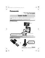
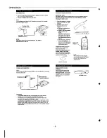
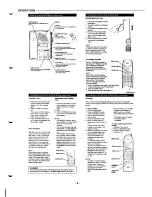
Page 56: ... J t 1 i CHARGER ...

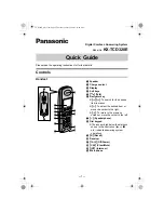
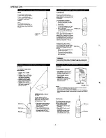
Page 57: ... I g t 1 I I WI A1l 11 l I I I I I E 8 J 1 I I I Y d L5TAT1Ul ET I I I l A e ...

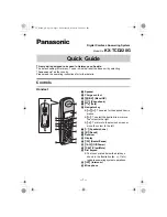
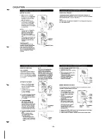
Page 58: ...I m I t I t T w w m B x m JJ ...

Page 59: ... 1 ...

Page 60: ...I k i WIRING DIAGRAM BASE STATION CONTROL BASE MAIN P W B CN401 1 L Lv L Ue This is a basic schematic diagram BASE CONTROL P W B 64 ...

Page 61: ...WIRING DIAGRAM OGM BASE OGM P W B I A u I 1 R51O O ohm Jumper Wire k 3 2 BASEMAIN P W B JJJ 65 ...

Page 62: ... ...

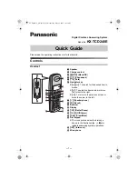
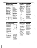
Page 63: ... F1 mm I g I A w 1 g z 0 ...

Page 64: ...42 o C 5 11 D456 P03 0 4 BAS A I N P02 I o RB ii 1D I ix LED INT o IN USE 1 CN451 Poo CHARGE ANS nPM Uul 1 I CN430 oBASE E IC431 kEWEa7J r I I I I e 1 CA3 2 0 1 9 SF o I 1 L 1 1 L L Cm ml II Ffc 7ix7ix OJ I I 1 1 w a C434 1 53 cd35 1 50 z ...

Page 65: ...5 1 0 7 7 10 7 8 1 PLAY MODE o Flash Flash o 0 0 0 0 0 0 4 8 0 7 7 9 7 7 9 Transistor No Q905 Q906 Q907 Q909 Q910 Measuring Pin Name E c B E c B E c B E c B E c B TALK MODE o 0 0 5 5 8 5 8 5 1 0 0 1 0 7 0 0 0 1 3 3 3 1 9 PLAY MOOE o 0 0 8 5 9 0 5 9 0 9 8 0 0 5 2 0 0 0 0 PLAY MODE 1 5 9 I 0 4 I 5 9 I Apr 1 951100 NS Printed in Japan 71 s O SANYO Electric Co Ltd Osaka Japan ...

Reviews: