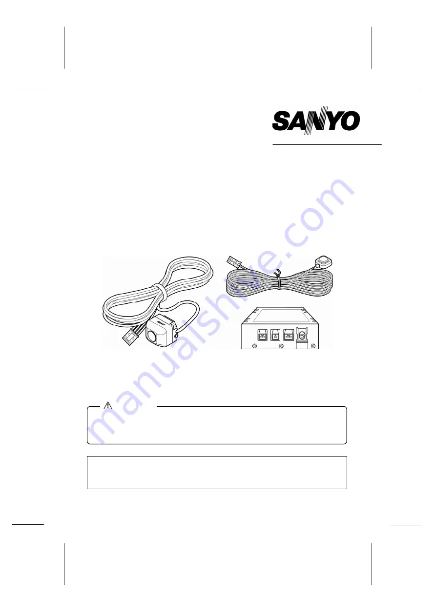
background image


INSTRUCTION MANUAL 

CCA-BC200


Rear View Back up Camera System 


SANYO’S HELP-LINE 

Call the toll-free number below if you have any difficulties operating this product. 

1-800-421-5013

 (Weekdays 7:30 AM – 5:00 PM, Pacific Time) 

  Installation and wiring require technical expertise and experience. To ensure 

proper installation and safety, consult the dealer where the product was 
purchased. 

CAUTION


Summary of Contents for CCA-BC200

Page 1: ...ll free number below if you have any difficulties operating this product 1 800 421 5013 Weekdays 7 30 AM 5 00 PM Pacific Time Installation and wiring require technical expertise and experience To ensure proper installation and safety consult the dealer where the product was purchased CAUTION ...

Page 2: ... 1 ...

Page 3: ... manual are not followed properly After using this instruction manual store it in a place where it can be easily located WARNING A WARNING indicates a situation in which serious injury or death could result if the warning is ignored CAUTION A CAUTION indicates a situation in which bodily injury or damage to objects or both could result if the caution is ignored WARNING Be sure to disconnect the ne...

Page 4: ...trated the Rear View Back up Camera System or liquid has spilled onto it which may produce smoke foul odor or abnormal noise discontinue use immediately and always consult the dealer where the Rear View Back up Camera System was purchased If the Rear View Back up Camera System continues to be used it could result in an accident fire or electrocution If power to the power cable has been cut or a fu...

Page 5: ... or re attaching the bracket weakens the adhesion strength The bracket may fall off resulting in an accident or injury This Rear View Back up Camera System has been designed to assist the driver in confirming the rear view when backing up the vehicle into a garage or when parallel parking For safety reasons it is important for the driver to take extra precautions when backing up Power Supply DC 12...

Page 6: ...ystem will not be damaged Screen flicker may occur while in fluorescent lit areas utilizing 50 Hz power supplies however this will not cause damage to the system Do not wipe the camera unit and lens area installation bracket or camera cable with volatile chemicals or cleaning agents containing alcohol benzene thinner or gasoline Use of these chemicals or cleaners will cause deformation deteriorati...

Page 7: ...ng with double sided tape ECU box 1 pc Electronic Control Unit box Bracket for camera 1 pc with double sided tape Screw for camera 2 pcs Hexagon type M3 x 6 Hexagon wrench 1 pc Double sided tape 1 pc for waterproof pad Waterproof pad 1 pc Cable tie 2 pcs Hook and loop fastener 1 set for ECU box Cable clamp 10 pcs Self lock conductor 1 pc for reverse signal detection Video output cable 1 pc Cleanin...

Page 8: ...efer to Step 3 on page 20 Offset Calibration If the camera is not installed in the center rear of the vehicle the offset can be corrected using the alignment function View from top Corrected center Standard view Deviated center Virtual camera Camera View from top Standard rear view Standard rear view Digitally corrected rear view Left right guide lines Green Guide lines to indicate width of vehicl...

Page 9: ... while pressing the connector lock If the cable is pulled it may come off causing a malfunction Do not splice the power supply cable to connect it to the power source of other devices A fire or electrocution could occur due to excess current flow on the power cable Always connect the red lead wire of the power supply cable to the accessory ACC power supply Do not connect this Rear View Back up Cam...

Page 10: ...erse signal cable of vehicle using self lock conductor included with the Rear View Back up Camera System Refer to How to use self lock conductor Power supply cable Brown Brown Connect to Camera input terminal or video input terminal on navigation or external monitor Control switch Control switch cable Self lock conductor Fuse 1A Video output cable RCA Type Yellow ECU box Yellow Red Black Connect t...

Page 11: ...e sides of the vehicle To assure that the camera remains firmly attached to the vehicle a Do not install the rear view back up camera system outdoors in rainy or foggy weather High humidity will prevent the camera from firmly adhering to the vehicle b If installation is required in areas of high humidity completely dry the surface where the camera installation bracket is to be installed c If the t...

Page 12: ...re adhering the bracket will weaken the adhesion strength Position the camera so that it is not aimed directly at the headlights of rear oncoming vehicles The recommended installation area is shown below Installing the camera outside of this area could result in reduced camera functionality and reduced rear view visibility Installing the camera on the rear spoiler or liftgate example The camera ca...

Page 13: ...will weaken the adhesion strength and result in a loose installation that could eventually fall off If the temperature where the camera bracket is to be installed is low warm the area with a hair dryer so that the tape adheres firmly to the surface Do not apply heat to the camera or the lens 3 Install the camera to the bracket using the screws Install the camera SANYO logo facing upward using the ...

Page 14: ...cle floor without using the mating piece Verify the tightness of the screws and tighten them more if necessary CAUTION Tighten Loosen Avoid installing near the ventilators for the heater CAUTION Approx 105 Approx 135 After installing the camera the screen displays an approximate 135 degree view between the left and right and an approximate 105 degree view between up and down The rear view back up ...

Page 15: ...self lock conductor and lock the reverse signal cable 3 Insert the reverse signal pick up cable Brown included with the system into the self lock conductor Insert the cable until it stops 4 Close the self lock cover and firmly lock it by pinching it with pliers Do not install the control switch in a position that obstructs vehicle operation CAUTION Vehicle reverse signal cable Cable stopper Revers...

Page 16: ...the liftgate hinge and harness cover Route the cable carefully so that the cable is not pinched when the door opens and closes Route the cable carefully to prevent water penetration Route the cable so that it does not block or obstruct vehicle operation Route the rear view camera cable as far away from the vehicle antenna as possible to prevent noise interference with AM radio band reception Also ...

Page 17: ...he liftgate Connecting Video Cable Connect the video output cable to the camera input terminal or video input terminal on the navigation system or external monitor Read the separate instruction manuals for these devices to connect them correctly Luggage finish plate Weather strip Position with no ribs on the rear side Waterproof pad 0 1 in 0 1 in Route the cable so that it does not obstruct vehicl...

Page 18: ... advance 1 Locate an area with parallel lines painted on a tarmac or similar flat surface such as a parking lot 2 Prepare markers to indicate the center line of the vehicle 3 Prepare two markers to indicate the width of the vehicle 4 Ruler to measure 1 5 ft and 3 ft and two markers Cans or bottles make good markers Marking tape for alignment is provided with this Rear View Back up Camera System to...

Page 19: ...corresponding to each alignment item moving from left to right with each rectangle having a different color 1 View from top angle alignment White 2 Center line alignment Red 3 View from top height alignment Violet 4 Left right guide lines alignment Yellow 5 Right guide line alignment Green 6 3 ft guide line alignment Light Blue 7 1 5 ft guide line alignment Blue If no picture appears on the screen...

Page 20: ...p angle alignment is now set and the screen changes to the center line alignment setting The center guide line is shown in red on the screen 2 Center line alignment flashing red rectangle 2 1 Each time the control switch is pressed the screen moves to the right Continuously pressing the control switch returns the screen to the left Align the center guide line with the center markers 2 2 Press and ...

Page 21: ...e lines alignment setting Left right guide lines are indicated in red on the screen 4 Left right guide lines alignment flashing yellow rectangle 4 1 Each time the control switch is pressed the width of the guide lines becomes narrower Continuously pressing the control switch sets the screen at the maximum width Set the left guide line to match the left side marker of the vehicle 4 2 Press and hold...

Page 22: ... alignment setting The 3 ft guide line is indicated in red on the screen 6 3 ft guide line alignment flashing light blue rectangle 6 1 Each time the control switch is pressed the 3 ft guide line moves farther from the vehicle Continuously pressing the control switch moves the line farther away until it exceeds a certain range and the line returns to the position closest to the vehicle Set the 3 ft...

Page 23: ...line to match the 1 5 ft marker 7 2 Press and hold the control switch for more than two seconds The 1 5 ft guide line alignment is now set and also 6 ft guide line alignment is now set automatically and all the alignment settings are now completed The screen will disappear after displaying the view from top for three seconds 8 After turning the ignition switch off and removing the auxiliary items ...

Page 24: ...ver remains responsible for being aware of and confirming the vehicle surroundings For safety reasons it is important for the driver to take extra precautions when backing up CAUTION Need help Call 1 800 421 5013 After the ignition switch is turned from off to the ACC ON or ON position a digitally corrected rear view is displayed on the screen first When changing the display mode the selected disp...

Reviews: