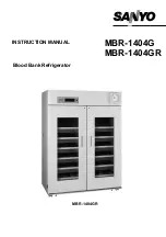
background image


MBR-1404G
MBR-1404GR

Blood Bank Refrigerator

INSTRUCTION MANUAL


MBR-1404GR 

Summary of Contents for BR-1404G

Page 1: ...MBR 1404G MBR 1404GR Blood Bank Refrigerator INSTRUCTION MANUAL MBR 1404GR ...

Page 2: ...inaccuracies SANYO Electric Biomedical Co Ltd All rights reserved Printed in Japan CONTENTS PRECAUTIONS FOR SAFE OPERATION P 2 CAUTIONS FOR USAGE P 7 ENVIRONMENTAL CONDITIONS P 8 REFRIGERATOR COMPONENTS P 9 INSTALLATION P 13 BEFORE COMMENCING OPERATION P 15 REMOTE ALARM TERMINAL P 15 START UP OF UNIT P 16 OPERATING INSTRUCTIONS P 17 ROUTINE MAINTENANCE P 19 TROUBLESHOOTING P 22 DISPOSAL OF UNIT P ...

Page 3: ...t in a hazard to personnel possibly resulting in serious injury or death CAUTION Failure to observe CAUTION signs could result in injury to personnel and damage to the unit and associated property Symbol shows this symbol means caution this symbol means an action is prohibited this symbol means an instruction must be followed Be sure to keep this manual in a place accessible to users of this unit ...

Page 4: ...re that a suitable fuse of adequate amperage is used to allow for compressor start up Remove dust from the power supply plug before inserting in a power source A dusty plug or improper insertion may pose a hazard Use a power supply outlet with ground earth to prevent electric shock If the power supply outlet is not grounded it will be necessary to install a ground by qualified engineers Never grou...

Page 5: ...ter directly onto the unit as this may cause electric shock or short circuit Never disassemble repair or modify the unit yourself Any such work carried out by an unauthorized person may result in fire or injury due to a malfunction Disconnect the power supply plug before replacement of the florescent light to prevent electric shock Disconnect the power supply plug if there is something wrong with ...

Page 6: ...e This may cause fire or electric shock Do not touch any electrical parts such as the power supply plug or any switches with a wet hand This may cause electric shock Do not put a container with water or heavy articles on the unit Injury may be caused if the articles fall Current leakage or electric shock may result from the introduction of spilled water into electrical components Do not climb onto...

Page 7: ... splashed water may cause current leakage or electric shock Be careful not to tip the unit over during movement to prevent damage or injury Disconnect the power plug when the unit is not used for long periods Do not put the packing plastic bag used in the packaging within reach of children as suffocation may result CAUTION ...

Page 8: ... case condensation forms on the front glass or frame due to a high humidity environment wipe if off with a soft and dry cloth 4 Do not clean the unit with scrubbing brushes acid thinner solvents powdered soap cleanser or hot water These agents can scratch the paint or cause it to peel Plastic and rubber parts can be easily damaged by these materials especially solvents When a neutral detergent is ...

Page 9: ...umidity 80 for temperature up to 31o C decreasing linearly to 50 relative humidity at 40o C 5 Mains supply voltage fluctuations not to exceed 10 of the nominal voltage 6 Other supply voltage fluctuations as stated by the manufacturer 7 Transient overvoltages according to Installation Categories Overvoltage Categories II For mains supply the minimum and normal category is II 8 Pollution degree 2 in...

Page 10: ...9 REFRIGERATOR COMPONENTS MBR 1404GR 1 2 3 4 5 6 7 8 9 10 11 12 13 14 15 16 17 ...

Page 11: ...ning or closing the door 8 Fluorescent light 40 W white light For the replacement refer to page 20 9 Light switch This switch is used for the fluorescent light 10 Air intake vent Ensure this vent is never blocked Failure to do so will result in unstable temperature distribution 11 Air exhaust vent Ensure this vent is never blocked Failure to do so will result in unstable temperature distribution 1...

Page 12: ...r side This spacer keeps the unit the proper distance from the wall This spacer is also available for metal fitting to prevent tipping 5 Evaporating tray rear side This is for evaporation of the drained water from evaporator 6 Power switch ON OFF 7 Battery switch ON OFF switch of installed battery for power failure alarm Make sure to turn on this switch when the unit is in operation Note Turn off ...

Page 13: ...rature Normally this key is not used 5 Digit shift key Pressing this key in the CAL mode will cause the changeable digits to move 6 Numerical value shift key Pressing this key in the CAL mode will cause the numerical value to change 7 Door check lamp DOOR This lamp is lit when the door is ajar or open 8 Alarm lamp ALARM This lamp is flashed during alarm condition 9 10 Temperature display monitor l...

Page 14: ...for installation This precaution will prevent the unit from tipping Improper installation may result in water spillage or injury from the unit tipping over 5 A location where objects will not fall on the unit CAUTION Never install the unit in a place where the possibility exists that an object may fall on it There are cooling circuits and electric components in the upper part of this unit Current ...

Page 15: ...Fix the cabinet to the wall with these hooks and rope or chain If holes can be opened on the wall open a hole with a 10 5 mm diameter and fix the cabinet by using the special bolt nut supplied with this cabinet This bolt nut can be used only on concrete walls See Fig 2 4 Ground earth WARNING Use a power supply outlet with ground earth to prevent electric shock If the power supply outlet is not gro...

Page 16: ... solution into the monitor bottle after removing the cap as shown in the figure 2 6 Cap the monitor bottle and return the bottle to its original position Route the lead wire through the hook on the wall 7 Attach the sensor to the bottle and replace the cover on the bottle REMOTE ALARM TERMINAL The terminal of remote alarm is located inside the front cover The signal is a dry contact Contact capaci...

Page 17: ...re 6 Turn on the light switch to ensure that the chamber light is properly functional 7 When you are satisfied that the unit is working correctly begin slowly placing product into the chamber to minimize the temperature rise Handling of containers Arrange containers so as not to disturb air circulation in the unit Disturbance of air circulation may cause freezing of contents or increase of tempera...

Page 18: ... average temperatures within the chamber Defrost cycles There is no need for routine defrosting of the unit as this occurs automatically as follows 1 Cycle defrost To keep the temperature stable inside the chamber the refrigeration compressor is cycled on and off During off periods any frost which has accumulated on the evaporator is melted by energizing a defrost heater This will not have any dis...

Page 19: ...short circuit Alarm lamp flashes Monitor bottle temp E2 are alternately displayed Defrost sensor goes open or short circuit Alarm lamp flashes Monitor bottle temp E3 are alternately displayed Thermal sensor abnormality Over temp sensor goes open or short circuit Alarm lamp flashes Monitor bottle temp E4 are alternately displayed Intermittent tone Remote alarm is active Note The remote alarm contac...

Page 20: ...he cabinet or accessories thoroughly with a cloth soaked in clean water Then wipe the cabinet or accessories unit with a dry cloth to eliminate the moisture Never pour water onto or into the unit Doing so can damage the electric shock or short circuit The compressor and other mechanical part are completely sealed This unit requires absolutely no lubrication There is a fan behind the compressor so ...

Page 21: ... drawers 4 In the case of MBR 1404GR after removing all drawers remove the rail that is placed vertically at the center of the frame 5 Pull the fluorescent light towards the rear together with the cover as shown in Fig 1 together with the wiring 6 Take out the fluorescent light and remove the connector water proofing rubber at both ends As shown in Fig 2 shift the rubber by rolling it 7 Remove the...

Page 22: ...ted 6 Wait for the temperature on the display to stabilize If the display is not 0o C calibrate using the following procedure If the display does indicate 0o C proceed to step 7 1 Press the CAL key for approximately 5 seconds until C00 is displayed 2 Enter the code of the probe to be calibrated using the numerical shift key Upper temperature sensor code is C01 Lower temperature sensor code is C02 ...

Page 23: ...m lamp and buzzer are activated follow the procedures to determine a cause On start up The temperature in the unit does not match a set value In use The door was kept opened for a long time Containers of high temperature load were put in the unit In these cases alarm is removed automatically by running the unit for several hours DISPOSAL OF UNIT WARNING If the unit is to be stored unused in an uns...

Page 24: ...tronic control system High temp alarm Changeable Lamp flashing Buzzer and remote alarm Low temp alarm Changeable Lamp flashing Buzzer Door alarm Door alarm lamp ON Buzzer after delay of 2 minutes Memory back up Nonvolatile static memory Fluorescent lamp White light 40 W x 1 Glow starter FG 4P Temperature recorder 7 day type Accessories 1 set of key 2 sets of bolt Battery 6 V 1100 mAh Ni MH Weight ...

Page 25: ...Unit interior No contamination Decontaminated Contaminated Others 3 Instructions for safe repair maintenance of the unit a The unit is safe to work on b There is some danger see below Procedure to be adhered to in order to reduce safety risk indicated in b below Date Signature Address Division Telephone Product name Blood Bank Refrigerator Model MBR 1404G MBR 1404GR Serial number Date of Installat...

Page 26: ...7FB6P101236004 5 April 2005 Recycled paper SANYO Electric Biomedical Co Ltd 10 15 Hongo 3 Chome Bunkyoku Tokyo 113 8434 Japan Printed in Japan ...

Reviews: