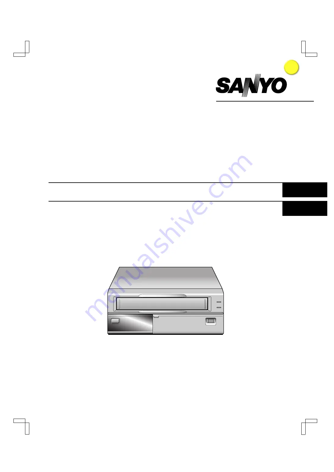
background image

INSTRUCTION MANUAL

SRC-850A

Video Cassette Recorder

English

Magnétoscope à Cassette

Français

Videograbador

Español

Please read this manual and accompanying “IMPORTANT SAFETY INSTRUCTIONS” sheet carefully before connecting
your VCR and operating it for the first time.
Be sure to read carefully and follow all the PRECAUTIONS on page 1 and 2.
Keep the manual in a safe place for future reference.

NF4Q/NA (SRC-850A GB)  Tue. Sept., 10/2002

I

i n d ex

Summary of Contents for audio system

Page 1: ...ease read this manual and accompanying IMPORTANT SAFETY INSTRUCTIONS sheet carefully before connecting your VCR and operating it for the first time Be sure to read carefully and follow all the PRECAUTIONS on page 1 and 2 Keep the manual in a safe place for future reference NF4Q NA SRC 850A GB Tue Sept 10 2002 I index ...

Page 2: ...ss B digital apparatus complies with Canadian ICES 003 This equipment has been tested and found to comply with the limits for a Class B digital device pursuant to part 15 of the FCC Rules These limits are designed to provide reasonable protection against harmful interference in a residential installation This equipment generated uses and can radiate radio frequency energy and if not installed and ...

Page 3: ...s this may cause playback or recording problems Avoiding Electrical Shock and Fire œ Do not handle the power cord with wet hands œ Do not pull on the power cord when disconnecting it from an AC wall outlet Grasp it by the plug œ If any liquid is spilled on the VCR unplug the power cord immediately and have the unit inspected at a factory authorized service center œ Do not place anything directly o...

Page 4: ...ND USAGE DURATION 33 OUTPUT TERMINALS 34 MAINTENANCE 38 TROUBLESHOOTING GUIDE 40 SPECIFICATIONS 41 WARRANTY 42 FEATURES œ Tape management function œ High speed Fast Forward Rewind œ Field recording playback œ Audio recording œ Autorepeat recording œ Series recording function œ Alarm recording function œ On screen mode setting œ Integrated time date generator œ Day Time search function œ Alarm scan...

Page 5: ...ALL RESET button I COUNTER RESET button j button J l button K TRACKING button SHIFT button ENTER button L TRACKING button SHIFT button CLEAR button M MENU button Press this button to display the menu Buttons I J K and L are used for menu control N ON SCREEN switch O Front door P Digital display panel REW FF STOP STILL PAUSE SEARCH MENU TRACKING c SHIFT b ON SCREEN MENU E X I T OFF ON MENU RESET AL...

Page 6: ...her types of display Refer to WARNING OUT Terminal on page 36 œ To cancel the display press the STOP button œ Recording playback speed mode œ Alarm search setting display œ Alarm scan setting display œ Day Time search setting display œ Time display No tape œ Linear time counter display Tape inserted œ Dew display œ Tracking control display œ Data transfer speed setting display œ Address setting di...

Page 7: ...rd pause REC PAUSE Playback PLAY Still image STILL Fast forward FF Rewind REW Forward picture search Reverse picture search Forward field advance Reverse field advance 5 OFF indicator Lights when the tape end has been reached after recording 6 Cassette indicator Lights when a cassette is loaded NF4Q NA SRC 850A GB Tue Sept 10 2002 6 English ...

Page 8: ... clock set trigger input terminal Q ALARM IN alarm trigger input terminal R VIDEO IN video input jack S VIDEO OUT video output jack T AUDIO OUT audio output jack U AUDIO IN audio input jack V MIC IN microphone input jack W REMOTE remote control input jack X AC power input NOTE œ The terminal may be damaged by a torque of 0 49 N m 5kg cm or more and by using screwdriver with a tip with a diameter o...

Page 9: ...VIDEO OUT jack From an external audio source To remote control sold separately Power cord To outlet MIC IN Power Cord Installation 1 Plug the supplied power cord firmly into the AC power input AC IN socket 2 Insert the plug of this power cord into a outlet NOTES œ The grounded power cord 3 pin plug must be connected to a grounded power outlet œ For more details please refer to the manuals accompan...

Page 10: ...the setting and move to the next item on the right CLEAR button œ When a sub menu is being displayed press this button and the MAIN MENU will appear œ If there are several items on one line press this button to move to the previous item on the left Sub menus To enter or modify settings within a sub menu 1 When a MAIN MENU is being displayed press the l or j button to select one of the sub menus th...

Page 11: ... are highlighted appear in blue characters when they are selected œ Settings flash while they are being changed œ When a menu is displayed recording will not be possible œ During recording or playback the menus cannot be displayed œ To reset the settings of a menu to their original values select the desired menu and then press the MENU RESET button œ The USED TIME data in the POWER FAILURE DEW USE...

Page 12: ...pears in blue characters 3 Press the ENTER button ø The month position starts flashing 4 Press the l or j button to set the month 10 then press the ENTER button ø The day of week is set automatically 5 Press the l or j button to set the day 15 then press the ENTER button 6 Press the l or j button to set the year 2002 then press the ENTER button 7 Press the l or j button to set the hours 15 for 3 P...

Page 13: ...adjustment is made œ Press the l or j button to set the week then press the ENTER button 1ST 2ND 3RD 4TH or LST first second third fourth or last œ Press the l or j button to set the day of week then press the ENTER button SUN MON TUE SAT Sunday Monday Tuesday Saturday œ Press the l or j button to set the month the daylight saving time adjustment is made then press the ENTER button 01 02 11 12 for...

Page 14: ...button 7 Press the l or j button to set Y displayed or N not displayed then press the ENTER button DATE The date appears TIME The time appears ALARM COUNT The number of alarm recordings appears 8 Repeat steps 6 and 7 when setting other items 9 When finished press the MENU EXIT button NOTE œ If the ON SCREEN switch is set to the ON position the items for which Y have been set are recorded The items...

Page 15: ...es that are damaged tapes that have been cut and repaired or tapes that have been altered in any way œ Some rewinders may tangle the tape and therefore their use is not recommended œ When tapes are recorded over and over again the recording quality will deteriorate Refer to Concerning the Number of Times Tapes can be Rerecorded on on page 19 and replace the tape with a new tape as required Loading...

Page 16: ...ton to select the 4 GENERAL SET line then press the ENTER button ø The GENERAL SET menu appears GENERAL SET TAPE IN MODE STOP TAPE END MODE REW CLOCK ADJUST 01 00 THREAD CHECK N VIDEO LOSS N REMOTE MENU VIDEO COLOR 3 Press the l or j button until the THREAD CHECK setting is highlighted then press the ENTER button 4 Press the l or j button to select the desired mode then press the ENTER button N Th...

Page 17: ...ready been recorded on the message USED TAPE will flash on screen until recording starts If tape management data is present on the tape The tape management data is checked and if there is no conflict the VCR will rewind the tape to the beginning then recording starts and the updated tape management data is recorded onto the tape The message T MANAGE OK appears on screen while the tape is being rew...

Page 18: ...of re recording times then press the ENTER button OFF The number of re recording times will not be checked 1 100 Maximum number of re recording times Refer to Concerning the Number of Times Tapes can be Rerecorded on on page 19 NOTES œ Since data is read before it is recorded the number of times will be incremented even if the recording is stopped before the end œ During autorepeat recording the r...

Page 19: ...JECT œ If the OVERRIDE is set to Y Yes the TAPE MANAGEMENT menu is displayed and conflicting setting preventing recording will flash and the VCR will switch to stop mode To enter recording mode press the REC button PROTECT DAY CONFLICT The tape is protected and the tape protection term ex 30 days is not yet over Under LAST M D the date of the last recording on the tape or the last expected recordi...

Page 20: ...ding Speed Mode Recording speed mode hour mode Maximum recording duration hours Recording interval second Audio recording Tape motion 8 8 1 60 Possible Continuous Record Pause Recording can be interrupted temporarily 1 Press the STILL PAUSE button during recording ø The pause still indicator flashes NOTES œ The image appears on screen but it is not recorded œ If a recording pause continues for 5 m...

Page 21: ...or rewind modes etc VIDEO LOSS can be displayed on screen If in the WARNING OUT EJECT SET menu VIDEO LOSS is set to Y the output at the WARNING OUT terminal becomes 0V Low Refer to WARNING OUT Terminal on page 36 1 Press the MENU button to display the MAIN MENU 2 Press the l or j button to select the 4 GENERAL SET line then press the ENTER button ø The GENERAL SET menu appears GENERAL SET TAPE IN ...

Page 22: ... active even if there was an alarm trigger 5 Press the MENU EXIT button Setting the video input signal The video input signal during recording can be set to either color or black white 1 Press the MENU button to display the MAIN MENU 2 Press the l or j button to select the 4 GENERAL SET line then press the ENTER button ø The GENERAL SET menu appears 3 Press the l or j button until the VIDEO settin...

Page 23: ...inning and recording will resume ø When the end of the tape is reached a buzzer will be heard if TAPE END in the BUZZER SET menu is set to Y OFF will be displayed and the TAPE END OUT terminal output will be 0 V until the rewinding operation starts 7 To stop recording press the STOP button NOTES œ If there is an alarm trigger during autorepeat recording AL and A flash on the digital display and al...

Page 24: ...uration 20S 40S 1M 2M 3M 4M 5M or CC then press the ENTER button 20S 5M Recording only for the displayed duration CC Recording as long as the alarm signal is being input minimum 5 seconds 7 Press the MENU EXIT button NOTES œ During alarm recording all buttons are disabled œ If OFF appears on the digital display alarm recording is not possible in order to prevent the recorded tape to be recorded ov...

Page 25: ... or j button to select the 8 OTHERS line then press the ENTER button ø The OTHERS menu appears OTHERS ALARM LOG POWER FAILURE DEW RS 485 SET STATUS INFO Y ALARM INFO Y 3 Press the l or j button to select the ALARM LOG line then press the ENTER button ø The ALARM LOG menu appears ø The number of alarm recordings and the 10 most recent alarm recording times are displayed Example ALARM LOG 010 001 12...

Page 26: ...rs on the digital display Alarm Scan To look for an alarm recording by viewing the first 5 seconds of each alarm recording 1 Press the SEARCH button twice during stop mode ø AL SCAN will be displayed on screen 2 Press the FF or REW button ø The unit will advance or rewind the tape at high speed and playback the first 5 seconds of every alarm recording ø To cancel the alarm scan mode press the STOP...

Page 27: ...cording to the TAPE END MODE setting in the GENERAL SET menu NOTES œ When using tapes that are based on the VHS standard a single tape can be used to record 8 00 00 or more based on the counter setting œ If SERIES REC is set to N in the ALARM SERIES REC SET menu series recording will not be possible œ The counter must start from the beginning of tape œ Even if OFF is displayed series recording wil...

Page 28: ... button repeatedly NOTE œ This function does not operate when a warning display appears on the digital display Picture Search Forward and Reverse 1 Press the FF or REW button during normal playback ø The image can be seen while the tape is advanced or rewound at high speed 2 To return to normal playback press the PLAY button NOTES œ During picture search noise horizontal bars will appear in the pi...

Page 29: ...p at the desired location In such a case use alarm scan to find the desired recording location œ The day time search function may not operate correctly if searching for a timer recording time or if the clock on the recording VCR has been adjusted using the CLOCK ADJUSTMENT function œ If a recording on a tape extends for over a one month period the same day may be present twice on the tape If such ...

Page 30: ...r j button to set Y sound a buzzer or N not sound a buzzer then press the ENTER button ALARM The buzzer will be heard during alarm recording TAPE END The buzzer will be heard when the end of the tape is reached during recording To stop the buzzer press the STOP EJECT PLAY FF or REW button KEY IN The buzzer will be heard when one of the VCR buttons is pressed WARNING The buzzer will be heard if the...

Page 31: ...s highlighted then press the ENTER button 4 Press the l or j button to set the hour at which the adjustment will be conducted then press the ENTER button NOTE œ The clock adjustment cannot be set to 00 00 Example GENERAL SET TAPE IN MODE STOP TAPE END MODE REW CLOCK ADJUST 03 00 THREAD CHECK N VIDEO LOSS N REMOTE MENU VIDEO COLOR 5 Press the MENU EXIT button The setting procedure on the first VCR ...

Page 32: ...ION setting is highlighted then press the ENTER button 6 Press the l or j button to select the desired operation then press the ENTER button SLAVE The function is restricted to only the VCR being operated MASTER The function is applied to the VCR being operated and all VCRs that are connected after it 7 Press the MENU EXIT button NOTE œ The EJECT button will not be operative during recording mode ...

Page 33: ...o select the 8 OTHERS line then press the ENTER button ø The OTHERS menu appears OTHERS ALARM LOG POWER FAILURE DEW RS 485 SET STATUS INFO Y ALARM INFO Y 3 Press the l or j button until the STATUS INFO setting is highlighted then press the ENTER button 4 Press the l or j button to set the STATUS INFO setting then press the ENTER button Y The VCR status information is output at the RS 485 connector...

Page 34: ...Y 12 25 07 30 DEW 001 FAILURE 12 25 11 00 RECOVERY 12 25 12 00 USED TIME VIDEO 00003H POWER 00007H POWER FAILURE The number of power failures and the date and time of the most recent power failure and recovery are displayed DEW The number of failures due to condensation and the date and time of the most recent failure and recovery are displayed USED TIME The video heads usage duration and the powe...

Page 35: ...ton until the TAPE END OUT setting is highlighted then press the ENTER button 4 Press the l or j button to select the desired mode then press the ENTER button 8 00 The output becomes 0 V Low when the tape counter reaches 8 00 00 and or when the tape reaches the end END The output becomes 0 V Low when the tape reaches the end NOTES œ If the SERIES REC is set to Y in the ALARM SERIES REC SET menu th...

Page 36: ...ress the ENTER button 4 Press the l or j button to select the desired output timing then press the ENTER button FIELD 1 pulse is output after each set number of fields FRAME 1 pulse is output after each set number of frames 5 Press the ENTER button 6 Press the l or j button to select the desired pulse signal interval 1 2 3 4 5 10 30 or 60 then press the ENTER button œ If TIMING is set to FRAME see...

Page 37: ... the VCR enters a mode other than recording i e recording pause stop mode etc during recording MECHA PROBLEM The output becomes 0 V and M appears on the digital display when the tape stops or other problem with the internal mechanism VIDEO LOSS The output becomes 0 V and V appears on the digital display when there is no video signal 7 Repeat steps 5 and 6 when setting other items 8 When finished p...

Page 38: ... or j button to select the 4 GENERAL SET line then press the ENTER button ø The GENERAL SET menu appears GENERAL SET TAPE IN MODE STOP TAPE END MODE REW CLOCK ADJUST 01 00 THREAD CHECK N VIDEO LOSS N REMOTE MENU VIDEO COLOR 3 Press the l or j button until the REMOTE setting is highlighted then press the ENTER button 4 Press the l or j button to select the desired switch mode then press the ENTER b...

Page 39: ...ly thanks to the automatic head cleaning function but due to factors such as the use of poor quality tape and the usage environment the heads could become dirty in a short time The video heads should be inspected every 1 000 hours of use to determine if they need to be replaced The video heads usage can be checked using the POWER FAILURE DEW USED TIME menu Cabinet Cleaning Clean the outside of the...

Page 40: ...E E ASSY BRAKE T E E E E ASSY BRAKE CAPSTAN E E E E ASSY BRAKE SOFT T E k Loading Drive System ASSY LOADING MOTOR E k DAMPER k COMPL GEAR WORM E k CAM MAIN k SPECIAL WASHER 3 6 X 0 5 E k GEAR WHEEL 1 k GEAR WHEEL 2 E k GEAR RELAY PINCH OPT k SLIDE CRECENT E k GEAR LOAD S E k GEAR RACK FRONT E k GEAR RACK START E k GEAR PINON E k Performance Check BACK TENSION TORQUE E E E E PB BACK TENSION TORQUE ...

Page 41: ...TAPE MANAGEMENT on page 16 Autorepeat recording is not possible AL appears on the digital display Display ALARM LOG menu then press the MENU RESET button to turn off the AL indicator Alarm recording is not possible OFF appears on the digital display Press the EJECT STOP FF REW or PLAY button to turn the indicator off Noise in the playback picture The video heads need cleaning Clean the video heads...

Page 42: ...rophone input 60 dBs 3 5 mm mini jack 10 kΩ unbalanced Connectors Alarm input No voltage make contact switch input Low input 100ms or more Normally 5 V Clock input No voltage make contact switch input Low input 100ms or more Normally 5 V Series input No voltage make contact switch input Low input 1s or more Normally 5 V Eject input No voltage make contact switch input Low input 100ms or more Norma...

Page 43: ...rating setup installation removal of the product for repair or reinstallation of the product after repair This warranty does not apply to repairs or replacements necessitated by any cause beyond the control of SFC including but not limited to any malfunction defect or failure caused by or resulting from unauthorized service or parts improper maintenance operation contrary to furnished instructions...

Page 44: ...NF4Q NA SRC 850A GB Tue Sept 10 2002 ...

Reviews: