


FILE NO.
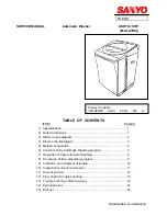
SERVICE MANUAL
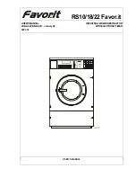
Automatic Washer
ASW U1100T
(MALAYSIA)
TABLE OF CONTENTS
ITEM
PAGES
1) Specifications ...............................................................................1
2) Outer dimensions .........................................................................1
3) Water course diagram ...................................................................2
4) Electric circuit diagram ................................................................3
5) Method of operation ....................................................................4
6) Content of fully Automatic Washing program ..............................5
7) Operation of fully Automatic Washing...........................................6
8) Procedure of time presetting program ..........................................9
9) Indication and judgment of trouble................................................10
10) Inspection mode of service man .................................................11
11) Care of service..............................................................................12
12) Flow chart of trouble shooting .....................................................15
13) Trouble shooting of Bearing Ass y ..............................................19
14) Exploded view...............................................................................21
15) Part list ........................................................................................24
REFERENCE.No.SM930202
Product Code No .
300-849-85 240V 50 Hz M3 H
Summary of Contents for ASW U1100T
Page 4: ... 3 4 Electric circuit diagram For the purpose of safety please use only designated parts ...
Page 22: ... 21 14 Exploded View ...
Page 23: ... 22 ...
Page 24: ... 23 ...
Page 25: ... 24 ...