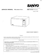
Sanyo 432-318-51, Service Manual
Discover the Sanyo 432-318-51 Service Manual, your ultimate companion for troubleshooting and maintaining this remarkable product. Unlock its full potential with our free download manual available exclusively at manualshive.com. Accessible, informative, and effortless, this manual guarantees a seamless user experience, ensuring your product's longevity and optimal functionality.
Share
Download


Reviews:
No comments
Related manuals for 432-318-51
700
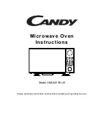
Brand: Candy Pages: 14
Convection Grill Combination Microwave
Brand: GE Pages: 6
Monogram ZMC1095 Series
Brand: GE Pages: 8
Monogram ZMC1095 Series
Brand: GE Pages: 36
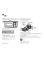
JEM31WF - Spacemaker II Microwave Oven
Brand: GE Pages: 2

Advantium SCA2000BCC
Brand: GE Pages: 3

JE740
Brand: GE Pages: 2

JE1340
Brand: GE Pages: 28

JE1423H
Brand: GE Pages: 31

JEB1095
Brand: GE Pages: 60

JES0737
Brand: GE Pages: 16

JEM25
Brand: GE Pages: 28

JES0738
Brand: GE Pages: 16
JES737
Brand: GE Pages: 16
JES1460DN
Brand: GE Pages: 36
JES1651
Brand: GE Pages: 36
JKP85 Series
Brand: GE Pages: 44
JKP86
Brand: GE Pages: 44


