background image

X

K

T

U

C

RC

(WD)

RC

(WL)

TRC

SC

85464359863005  ©SANYO 2007

– Split System Heat Pump Air Conditioner –

INSTALLATION  INSTRUCTIONS
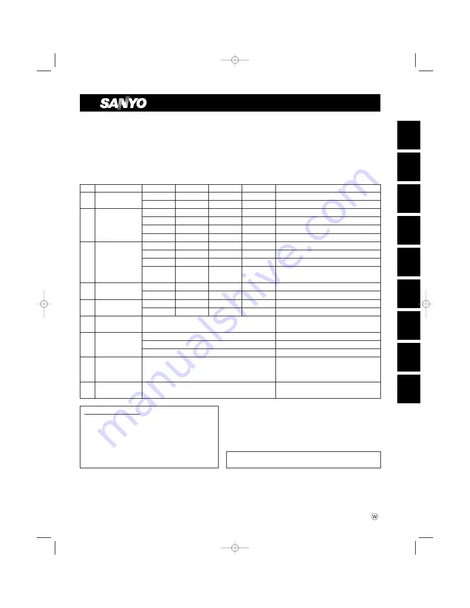
Model Combinations

Combine indoor and outdoor units only as listed below.

Indoor Units and Outdoor Units

* When air discharge chamber is installed.

OPERATING LIMITS

Maximum Conditions

Cooling

/ Heating

Outdoor temperature : 109°F DB / 65°F WB

Room temperature

: 71°F WB

/ 80°F DB

Minimum Conditions

Outdoor temperature : 0°F* DB

/ 5°F WB

Room temperature

: 57°F WB

/ 59°F DB

Units should be installed by licensed contractor according to
local code requirements.

Indoor Unit Type

26

30

36

42

Remarks

X

4-Way Air Discharge XH2672R

XH3672R

XH4272R

Optional remote controller

Semi-Concealed

XHW2672R

XHW3672R

XHW4272R

with Wired Remote Controller: RCS-TM80BG

KH2672R

KH3072R

KH3672R

Optional remote controller

K

Wall-Mounted

KHS2672R

KHS3072R

KHS3672R

with Wireless Remote Controller: RCS-SH1UA

KHH2672R

Optional remote controller

KHHS2672R

with Wireless Remote Controller: RCS-SH1UA

TH2672R

TH3672R

TH4272R

Optional remote controller

THW2672R

THW3672R

THW4272R

with Wired Remote Controller: RCS-TM80BG

T

Ceiling-Mounted

THH2672R

THH3672R

Unit with Back-up heater

THHW2672R

THHW3672R

Unit with Back-up heater 
with Wired Remote Controller: RCS-TM80BG

U

Concealed-Duct

UH2672R

UH3672R

Optional remote controller

UHW2672R

UHW3672R

with Wired Remote Controller: RCS-TM80BG

C

Outdoor Units

CH2672R

CH3072R

CH3672R

CH4272R

H/P

C2672R

C3072R

C3672R

C4272R

S/C

RC

Wired Remote

RCS-SH80UG (Optional part)

(WD) Controller

RC

Wireless Remote

Built-in type:  RCS-SH80UA.WL (Optional part)

for X and T type Indoor units

(WL)

Controller

External type: RCS-BH80UA.WL (Optional part)

for U type Indoor units

Built-in type:  RCS-SH80UA (Accessory part / Optional part)

for K type Indoor units

Timer Remote

for X, T and U type Indoor units.

TRC

Controller

RCS-TM80BG* (Accessory part / Optional part)

* Timer Remote Controller comes with 

Owner’s Manual and Installation Instructions.

SC

System Controller

SHA-KC64UG (Optional part)

SANYO Commercial Solutions

In Canada

A division of SANYO North America Corporation

SANYO Canada Inc.

Cornerstone Business Park

1-300 Applewood Crescent

1062 Thorndale Avenue

Concord, Ontario

Bensenville, IL 60106, U.S.A.

L4K 5C7, Canada

07-115 SSHP_II  5/7/07  3:59 PM  Page a

Summary of Contents for 200 BTU

Page 1: ...roller THW2672R THW3672R THW4272R with Wired Remote Controller RCS TM80BG T Ceiling Mounted THH2672R THH3672R Unit with Back up heater THHW2672R THHW3672R Unit with Back up heater with Wired Remote Controller RCS TM80BG U Concealed Duct UH2672R UH3672R Optional remote controller UHW2672R UHW3672R with Wired Remote Controller RCS TM80BG C Outdoor Units CH2672R CH3072R CH3672R CH4272R H P C2672R C30...

Page 2: ... and outdoor units Get a partner to help and bend your knees when lifting to reduce strain on your back Sharp edges or thin aluminum fins on the air conditioner can cut your fingers When Installing In a Room Properly insulate any tubing run inside a room to prevent sweating that can cause dripping and water damage to walls and floors In Moist or Uneven Locations Use a raised concrete pad or concre...

Page 3: ...wer etc Most importantly the multi air conditioner system is able to replenish a large amount of refrigerant com pared to conventional individual air conditioners If a single unit of the multi air conditioner system is to be installed in a small room select a suitable model and installation procedure so that if the refrigerant acci dentally leaks out its density does not reach the limit and in the...

Page 4: ...ower performance and cause defects of the unit 2 2 Since refrigerant composition changes and performance decreases when gas leaks collect the remaining refrigerant and recharge the required total amount of new refrigerant after fixing the leak 3 Different tools required 3 1 Tool specifications have been changed due to the characteristics of R410A Some tools for R22 and R407C type refrigerant syste...

Page 5: ...o change Thus do not use the refrigerant if the amount in the charging cylinder is less than 20 Also charge the minimum necessary amount to the charging cylinder before using it to charge the air conditioning unit Valve Single valve Charge liquid refrigerant with cylinder in up side down position Single valve with siphon tube Charge with cylinder in normal position Liquid Valve Liquid Configuratio...

Page 6: ...ation Alarm Indicators Page IMPORTANT 2 Please Read Before Starting Check of Density Limit Precautions for Installation Using New Refrigerant 1 GENERAL 8 1 1 Tools Required for Installation not supplied 1 2 Accessories Supplied with Outdoor Unit 1 3 Type of Copper Tube and Insulation Material 1 4 Additional Materials Required for Installation 1 5 Tubing Size 2 SELECTING THE INSTALLATION SITE 16 2 ...

Page 7: ...g 8 4 Mode Setting 8 5 How to Perform Zone Registration 8 6 Connection with Other Equipment 8 7 Memory Back Up Switch 8 8 Test Run 9 HOW TO PROCESS TUBING 97 9 1 Connecting the Refrigerant Tubing 9 2 Connecting Tubing between Indoor and Outdoor Units 9 3 Insulating the Refrigerant Tubing 9 4 Taping the Tubes 9 5 Finishing the Installation 10 LEAK TEST EVACUATION AND ADDITIONAL REFRIGERANT CHARGE 1...

Page 8: ...ish to purchase these materials separately from a local source you will need 1 Deoxidized annealed copper tube for refrigerant tubing 2 Foamed polyethylene insulation for copper tubes as required to precise length of tubing Wall thickness of the insulation should be not less than 5 16 in 3 Use insulated copper wire for field wiring Wire size varies with the total length of wiring Refer to Section ...

Page 9: ...Full scale diagram Wall fixture 2 Rawl plug 2 Cover 2 Tapping screw 2 Insulator Tube connector Truss head Phillips 4 5 8 in Truss head Phillips 4 1 in For supporting indoor unit For insulation of tubing of the indoor unit For securing indoor unit For attaching wall fixture For determining location where indoor unit is installed For supporting indoor unit For attaching wall fixture For improved tub...

Page 10: ...with 7 7 8 in wire Black White Part Name Figure Q ty Remarks Flare insulator 2 Insulating tape 2 2 Tapping screw TOTA4 10 14 or 20 or 24 Jumper cable 1 Hose band 1 Packing 1 Sealing putty 1 Drain insulator 1 Drain hose 1 Drain hose adaptor 1 Clamp 9 Tube connector 1 For gas and liquid tubes For gas and liquid tubes For gas and liquid tube flare nuts For air intake duct connection For increasing fa...

Page 11: ...ws Batteries 4 5 8 in Q ty Q ty Wireless remote controller mounting cradle Table 1 6 Accessories for the Wireless Remote Controller RCS SH80UA WL Part Name Figure Q ty Part Name Figure Q ty Operation controller 1 Spacers 2 Indicator section 1 4 Wireless remote controller 1 2 1 3 Batteries 2 Wire joints 4 Pan head tapping screws 4 13 32 in Truss head tapping screws 4 5 8 in Run Timer Heating prepar...

Page 12: ... ZONE3 Central Control ZONE3 RCU ZONE4 Central Control Please attach this label on surface of the lid after cleaning If need to write down some detail use magic marker ZONE4 RCU ALL ON INPUT ALL OFF INPUT COMMON INPUT COMMON OUTPUT OPERATION STATE OUTPUT ALARM OUTPUT U1 U2 Inter unit control wiring U2 Aux UNUSED DC12V FROM INDOOR UNIT PCB Small screws M4 1 9 16 in Machine screws M4 1 in Ceiling in...

Page 13: ...tubing work try to make both the tubing length L and the difference in elevation H1 as short as possible Refer to Table 1 10 Table 1 9 Single Main tubing L H1 H1 H1 100 50 Maximum indoor outdoor height difference If outdoor unit is higher If outdoor unit is lower Indoor unit type 26 30 36 types 42 type Maximum length 165 ft 165 ft Charge less tubing length actual length 10 100 ft 15 100 ft Additio...

Page 14: ... 8 15 88 5 8 15 88 Limit of tubing length ft 165 165 165 Outdoor unit is placed 100 100 100 higher ft Outdoor unit is placed 50 50 50 lower ft Max allowable tubing length at shipment ft 10 100 10 100 10 100 Required additional refrigerant 1 oz ft a 0 43 b 0 43 b 0 43 Refrigerant charged at shipment lbs 4 2 6 2 7 9 Table 1 10 Tubing Data for Models 26 42 ø5 8 ø3 8 0 43 oz Gas tube Liquid tube Main ...

Page 15: ...volume 44 66 88 lbs Range below the density limit of 0 3 oz ft 3 Countermeasures not needed Range above the density limit of 0 3 oz ft 3 Countermeasures needed Check of limit density When installing an air conditioner in a room it is neces sary to ensure that even if the refrigerant gas acciden tally escapes its density does not exceed the limit level If the density might exceed the limit level it...

Page 16: ...ation where the ceiling is strong enough to support the weight of the unit select a location where tubing and drain pipe have the shortest run to the outdoor unit allow room for operation and maintenance as well as unrestricted air flow around the unit install the unit within the maximum elevation difference above or below the outdoor unit and within a total tubing length L from the outdoor unit a...

Page 17: ...ground level to reduce humidity and protect the unit against possible water damage and decreased service life Fig 2 4 use lug bolts or equal to bolt down unit reducing vibration and noise 4 2 3 1 More than 25 64 More than 3 3 ft More than 25 64 Inlet side C Outlet side CAUTION Concerning inlet side distance C Fig 2 2 The minimum for distance C is 6 if there are no obstructions on the outlet side w...

Page 18: ...o the unit may occur b There may be no air flow c The tubing may freeze and burst d The condenser pressure may drop because of strong wind and the indoor unit may freeze 2 5 Precautions for Installation in Heavy Snow Areas 1 The platform should be higher than the max snow depth Fig 2 6 2 The 2 anchoring feet of the outdoor unit should be used for the platform and the platform should be installed b...

Page 19: ... Rectangular hole Rectangular hole Rectangular hole 11 13 16 2 1 4 3 9 7 16 1 3 8 12 15 32 21 5 32 2 3 4 21 13 32 1 1 22 13 32 42 29 32 39 1 4 9 27 32 9 27 32 12 7 32 9 27 32 1 Unit front air discharge chamber 2 Unit left side air discharge chamber 3 Unit light side air discharge chamber 4 Reinforcement brackets 4 locations STK DRV80U for 2672R 3072R 3672R unit STK DRE140A for 4272R unit Unit inch...

Page 20: ...n Wind direction Wind direction 37 30 23 32 23 32 9 27 32 21 5 8 4 1 16 5 3 16 Wind direction 4 5 16 25 31 32 6 11 16 1 2 1 2 13 3 8 15 15 16 14 31 32 13 32 19 32 25 32 25 32 1 2 2 11 36 21 13 32 11 13 16 Wind direction Wind direction 37 23 32 48 7 16 Wind direction Wind direction Wind direction Wind direction 11 13 16 4 1 4 39 1 4 Wind direction Wind direction 4272R unit with STK DRE140A Unit inc...

Page 21: ...f the outdoor unit the obstacle at either the front or rear must be no taller than the height of the outdoor unit 2 Multiple unit installation Installation in lateral rows CAUTION The front and top must remain open The obstacles must be no taller than the height of the outdoor unit CAUTION The front and both sides must remain open Installation in front rear rows Installation with intakes facing ou...

Page 22: ...oof vent 25 13 32 17 15 32 9 3 16 16 25 32 27 29 32 3 31 32 11 29 32 16 25 32 9 3 16 27 29 32 30 3 32 1 4 5 6 2 1 21 32 25 32 5 3 32 19 11 16 9 3 8 30 11 16 28 3 4 19 11 16 5 8 13 25 32 3 3 4 Fastened by screws at 13 locations Fastened by screws at 3 locations also on reverse side Fastened by screw at 1 location also on reverse side Unit anchor hole 6 ø7 hole 1 Unit top snow proof vent 2 Unit left...

Page 23: ...2 25 13 32 7 1 16 2672R 3072R 3672R unit with STK BDRE80A 11 29 32 16 3 4 15 15 16 14 31 32 13 32 19 32 25 32 30 3 32 25 13 32 7 1 16 3 4 30 23 32 37 Wind direction Wind direction Wind direction Wind direction Wind direction Wind direction Dimensions of outdoor unit with snow proof vents field supply 4272R unit with STK BDR140U Unit inch Unit inch 07 115 SSHP_II 5 7 07 3 59 PM Page 23 ...

Page 24: ...e unit installation 2 or more units Note In cases 2 and 3 the height of the obstacle must be no taller than the height of the outdoor unit 2 Obstacles on both sides Top is open Top is open Top is blocked by an obstacle Top is blocked by an obstacle C H 2672R 3072R 3672R 4872R Outdoor unit A B C D E F G 5 29 32 5 29 32 11 13 16 7 7 8 11 13 16 5 29 32 7 7 8 Outdoor unit H 19 11 16 C H 2672R 3072R 36...

Page 25: ...ttached after the unit is installed verify that dimension Q is 19 11 16 in or more Dimension Q If a snow protection duct is attached after the unit is installed verify that dimension Q is 19 11 16 in or more The top and both sides must remain open Either the obstacle to the front or the obstacle to the rear must be no taller than the height of the outdoor unit The top and both sides must remain op...

Page 26: ...n the positions of the sus pension fitting the unit and the panel Type Length Table 3 2 Unit inch mm XH W 2672R PNR XH2442 XH W 3672R XH W 4272R PNR XH3632 A 6 3 16 157 6 3 16 157 7 5 32 182 7 5 32 182 10 9 32 261 11 15 32 291 12 1 8 308 13 1 16 338 4 7 8 124 4 7 8 124 D E B C Hole in anchor Hole in plug Concrete Insert Suspension bolt M10 or 3 8 field supply Fig 3 1 g n i n e p o g n i l i e C 2 ...

Page 27: ...appropriate for a distance between the bottom of the bolt and the bottom of the ceiling of 19 32 in or more as shown in Fig 3 4 3 Thread the 2 hexagonal nuts field supply and washers onto the 4 suspension bolts as shown in Fig 3 5 Use 2 sets of nuts and washers upper and lower so that the unit will not fall off the suspension lugs 4 Remove the protective cardboard used to protect the fan parts dur...

Page 28: ...raised a maximum of 19 11 16 in Do not raise it any higher than 19 11 16 in as this could result in water leaks Fig 3 9 Do not install the pipe with an upward gradient from the connection port This will cause drain water to flow backwards and leak when the unit is stopped Fig 3 10 Do not apply force to the piping on the unit side when connecting the drain pipe The pipe should not be allowed to han...

Page 29: ...ing Test Run be sure to observe the Test Run procedure Refer to page 105 3 After drain checking is finished return the Opera tion Selector switch to the RUN position ON posi tion and remount the tube cover WARNING Do not supply power to the unit until the tubing and wiring to the outdoor unit are completed CAUTION Be careful since the fan will start turning when checking the drainage WARNING To mo...

Page 30: ...ards you to remove it from the ceiling panel 2 Pull down the two panel catches on the body of the indoor unit body Fig 3 15 CAUTION Never touch or attempt to move the air direction louver by hand or you may damage the unit Instead use the remote control unit if you want to change the direction or air flow Ceiling panel Air intake grille Latch Screw Safety cord Air filter 45 Fig 3 13 Fig 3 14 Fig 3...

Page 31: ... has been properly aligned use the supplied 4 mounting screws M5 with washers to permanently fasten the ceiling panel 4 Install the wiring connector from the ceiling panel to the connector in the electrical component box of the indoor unit After installing the connector use the clamp on the body of the indoor unit to secure the wiring 5 Install the air filter and air intake grille by perform ing t...

Page 32: ...f the air intake plenum and fasten it to both sides of the indoor unit and plenum with the accessory screws M4 L1 2 in 3 pcs Fig 3 18 c Installing the indoor unit Install the indoor unit to the ceiling Install the indoor unit according to items 3 1 to 3 6 CAUTION When installing in a pre existing location install the indoor unit before installing the duct connection box Air intake plenum Type CMB ...

Page 33: ... intake plenum and pass the 8P sockets through it Fix the panel lead wire with the chamber side clamp Fig 3 17 Connect the 8P socket electrical component box side to the 8P socket ceiling panel side of the indoor unit electrical component box Reattach the socket cover Ceiling panel Panel catch Installation screws M4 1 2 in Duct connection flange Duct connection box Fig 3 18 07 115 SSHP_II 5 7 07 3...

Page 34: ...autions are also applicable if tubing goes through the wall in any other location 4 Using a sabre saw key hole saw or hole cutting drill attachment cut a hole in the wall See Table 3 3 and Fig 3 22 Table 3 3 5 Measure the thickness of the wall from the inside edge to the outside edge and cut PVC pipe at a slight angle 1 4 shorter than the thickness of the wall Fig 3 23 6 Place the plastic cover ov...

Page 35: ...recaution if the tubing goes through a wall at any other location 4 Using a sabre saw key hole saw or 3 5 32 in hole cutting drill attachment make a hole in the wall The required minimum hole diameter for these models is 3 3 16 in Fig 3 26 5 Measure the thickness of the wall from the inside edge to the outside edge and cut PVC pipe at a slight angle 1 4 in shorter than the thickness of the wall Fi...

Page 36: ...g 3 29 Tape m a r g a i d n o i t a l l a t s n i e l a c s l l u F Fig 3 30 3 Using a sabre saw key hole saw or 3 5 32 in hole cutting drill attachment make a hole in the wall The required minimum hole diameter for these models is 3 3 16 in Fig 3 31 4 Measure the thickness of the wall from the inside edge to the outside edge and cut PVC pipe at a slight angle 1 4 in shorter than the thickness of ...

Page 37: ... wall Insert rawl plugs for appropri ate mounting screws Fig 3 36 Confirm that the wall is strong enough to support the unit a If Wooden Wall 1 Attach the wall fixture to the wall with the 12 screws pro vided Fig 3 37 If you are not able to line up the holes in the wall fixture with the beam locations marked on the wall use rawl plugs or toggle bolts to go through the holes on the panel or drill 3...

Page 38: ...nel over the stud locations and then mount the wall fixture 2 Check with a tape measure or carpenter s level that the wall fixture is level This is important so that the unit is correctly installed 3 Make sure the wall fixture is flush against the wall Any space between the wall and unit will cause noise and vibration b If the Wall is Brick Concrete or Similar Drill 3 16 in dia holes in the wall I...

Page 39: ...rd screwdriver to push up the 3 tabs to remove the grille Fig 3 40b c Pull the lower part of the grille toward you to remove Fig 3 40a How to replace the grille 1 Close the flaps 2 Reinstall the grille into the lower part while aligning its tabs on the upper part Fig 3 41a Insert the tabs in the slots and push the lower part of the grille back into position 3 Press at each of the 5 tabs to complet...

Page 40: ...p in the horizontal position Fig 3 45 5 Remove the 3 screws Fig 3 45 6 Remove the grille Fig 3 45 When replacing the grille be careful not to crush the lead wires between the grille and the frame Fig 3 45 NOTE Plastic cover Screw Fig 3 42 Clamp Screw Fig 3 43 Wiring connectors Fig 3 44 Frame Flap Grille Screws Fig 3 45 KH S 3072R KH S 3672R 07 115 SSHP_II 5 7 07 4 00 PM Page 40 ...

Page 41: ...indoor unit Use a flare nut Fig 3 49 Arrangement for Right Tubing a Remove the 2 screws and take off the side cover Fig 3 48 b Cut out the L shaped tubing outlet using a hacksaw Fig 3 50 c Using the L shaped tube field supply connect tubing between the indoor and outdoor units Fig 3 52 Arrangement for Left and Left rear Tubing a Remove the 4 screws 2 on each side and take off both left and right s...

Page 42: ...sed exclusively for each unit A power supply disconnect and circuit breaker for overcurrent protection should be provided in the exclusive line 3 To prevent possible hazards from insulation failure the unit must be grounded 4 All wiring must be connected tightly 5 Do not allow wiring to touch refrigerant tubing compressor or any moving parts of the fan KHH S 2672R Left rear tubing Left tubing Righ...

Page 43: ...t wiring to the corresponding terminals on the terminal plate Figs 3 58a and 3 58b while referring to the wiring diagram 4 Be sure to secure the wiring with the provided clamp How to remove the cover plate To access the terminal plate inside the indoor unit follow these steps 1 Using a Phillips screwdriver remove the screw on the cover plate Figs 3 58a and 3 58b 2 Remove the cover plate KH S 2672R...

Page 44: ...nut Fig 3 60 or 3 61 4 Give some play to the inter unit wiring from the outdoor unit to the corresponding terminals on the terminal plate 5 Secure the metallic cover with its screw Then replace the side cover CAUTION Be sure to refer to the wiring system diagram label inside the metallic cover and carry out the correct field wiring Wrong wiring can cause the unit to malfunction Check local electri...

Page 45: ...efrigerant tube and drain hose in the desired direction so that they can easily go into the wall hole Fig 3 66 2 Push the wiring narrow tube and drain hose through the hole in the wall 3 Bend the tubing if necessary to run along the wall in the direction of the outdoor unit then tape as far as the fittings The drain hose should come straight down the wall to a point where water runoff won t stain ...

Page 46: ...ing Tubing between Indoor and Outdoor Units 5 Assemble the refrigerant tubing drain hose and inter unit wiring as shown in Fig 3 71 3 18 Installing the Drain Hose 1 The drain hose should be slanted downward on the outdoor side Fig 3 72 2 Never form a trap in the course of the hose 3 If the drain hose will run in the room insulate the hose so that chilled condensation will not damage furniture or f...

Page 47: ...ling supports or construct a suitable support as shown in Fig 3 76 NOTE WARNING It is important that you use extreme care in supporting the indoor unit from the ceiling Ensure that the ceiling is sufficiently strong enough to support the weight of the unit Before hanging the ceiling unit test the strength of each attached suspension bolt 4 Screw in the suspension bolts allowing them to protrude fr...

Page 48: ...spending the indoor unit The suspension method varies depending on whether the unit is next to the ceiling or not Figs 3 80 and 3 81 e d i l S Hinge Air intake grille Pull out the air Intake grille pushing claws of the hinges Screw Latch Fig 3 78 Slide toward front side Side panel Fig 3 79 unit Suspension bolt field supply Ceiling surface Washer supplied Double nut field supply Fixture Fig 3 80 un...

Page 49: ...ays level Please confirm that the indoor unit is evenly suspended For the installation to be correct leave a clearance of about 3 8 in between the ceiling panel and the ceiling surface and fill the gap with an appropriate insulation or filler material 8 If the tubing and wiring are to go towards the rear of the unit make holes in the wall Fig 3 85 9 Measure the thickness of the wall from the insid...

Page 50: ...he course of the piping Insulate any piping inside the room to prevent dripping Use the supplied drain pipe to connect the drain pipe with the drain outlet of the indoor unit After connecting the drain pipe securely wrap the supplied drain pipe insulator around the pipe seal the gap at the drain socket with the supplied black insulation tape then secure it with clamps Fig 3 90 After the drain pipi...

Page 51: ...rt O D 1 1 4 in Bottom drain port O D 1 1 32 in Suspension lug Power supply outlet 2 ø1 3 16 hole Fresh air intake port ø5 29 32 hole Flange for the flexible air outlet duct ø7 7 8 hole Tube cover Electrical component box Flange for the air intake duct Option or field supply 9 10 9 10 11 11 Suspension bolt pitch h c t i p t l o b n o i s n e p s u S M ø1 8 Hole 4 ø15 32 Hole Hole A O D L ø1 4 I 13...

Page 52: ...rom the ceiling as shown in Fig 3 93 Cut the ceiling material if necessary 3 Thread the 2 hexagonal nuts and washers field supply onto the 4 suspension bolts as shown in Figs 3 95 and 3 96 Use 2 sets of nuts and wash ers upper and lower so that the unit will not fall off the suspension lugs WARNING It is important that you use extreme care in supporting the indoor unit inside the ceiling Ensure th...

Page 53: ...upplied packing and drain pipe insulator around the pipe then secure it with the supplied clamps Fig 3 99 Make sure the drain pipe has a downward gradient 1 100 or more and that there are no water traps NOTE CAUTION Tighten the hose clamps so their locking nuts face upward Fig 3 98 Air outlet duct Air outlet grille Ceiling material Indoor unit Bolt anchor Suspension bolt Air intake duct Air intake...

Page 54: ...ollowing procedure to check that the water will drain smoothly For this prepare a bucket and wiping cloth to catch and wipe up spilled water 1 Connect power to the power terminal board L1 L2 terminal inside the electrical component box 2 Remove the tube cover and through the opening slowly pour about 43 oz of water into the drain pan to check drainage 3 Short the check pin CN5 white on the indoor ...

Page 55: ... HT H M and L fan speed control are shown The nameplate values are shown based on the H air flow For the 26 type the air flow is 636 CFM while the external static pressure is 49 Pa at H position If external static pressure is too great due to long extension of duct for example the air flow volume may drop too low at each air outlet This problem may be solved by increasing the fan speed as explaine...

Page 56: ...struction manual of the drain socket optional part STK DS25T 4 3 Routing the Tubing and Wiring The tubing and wiring can be extended out in 4 directions front rear right and down The service valves are housed inside the unit To access them remove the inspection panel To remove the inspec tion panel remove the 3 screws then slide the panel downward and pull it toward you 1 If the routing direction ...

Page 57: ...l wiring and the inter unit control wiring should be wired apart from the inter unit power wiring Use shielded wires for inter unit control wiring between units and ground the shield on both sides 9 If the power supply cord of this appliance is dam aged it must be replaced by a repair shop appointed by the manufacturer because special purpose tools are required 10 All wiring used must be Class 1 5...

Page 58: ...vided between power source and indoor unit NOTE 1 2 G Inter unit power wiring U1 Inter unit control wiring U2 5P terminal board X T U Type Remote controller wiring Inter unit control wiring 4P terminal board 1 2 G Inter unit power wiring U1 U2 K Type Remote controller wiring Indoor Unit Control Wiring Type B Power Supply AWG 14 C Inter Unit Control Wiring D Remote Control Wiring E Control Wiring F...

Page 59: ...a wire cutter or wire cutting pliers then strip the insulation to expose the stranded wiring about 3 8 in Fig 5 1 2 Using a Phillips head screwdriver remove the ter minal screw s on the terminal plate 3 Using a ring connector fastener or pliers securely clamp each stripped wire end with a ring pressure terminal Fig 5 1 4 Place the ring pressure terminal and replace and tighten the removed terminal...

Page 60: ... Never cover the remote controller or recess it into the wall Drainage Work When mounting the remote controller on a wall refer to Figs 6 1 and 6 2 6 HOW TO INSTALL THE WIRED REMOTE CONTROLLER OPTIONAL PART Fig 6 1 3 21 32 in or more Spacer Wall Hole for routing remote control cable 3 17 32 in or more 4 29 32 in or more 4 29 32 in or more from wall when continuous installation from wall when conti...

Page 61: ... completed CAUTION Do not twist the control wiring with the power wiring or run it in the same metal conduit because this may cause malfunction Install the remote controller away from sources of electrical noise Install a noise filter or take other appropriate action if electrical noise affects the power supply circuit of the unit If local electrical codes allow this remote controller can be mount...

Page 62: ... setting is automatically executed after turn ing on the system An indoor unit address is assigned to each indoor unit Operation takes place successively at intervals of 1 second by using combinations of the address setting of each unit CAUTION Carry out wiring correctly incorrect wiring will damage the equipment Diagram of outer dimensions 5 32 4 23 32 5 8 2 3 3 2 3 3 2 4 Fig 6 5 Shielded wire Gr...

Page 63: ... controllers up to 2 of them can be used one is the main remote controller and the other is the sub remote controller To set up a sub remote controller change its remote control address connector RCU ADR located on its PCB from main to sub position main when shipped from factory sub 1 2 Wire joint Remote controller main Ground earth Connection wiring for group control 1 2 U1U2 U1U2 U1U2 U1U2 U1U2 ...

Page 64: ...cedure if you must use the sensor on the remote controller 1 Press and hold the buttons for at least 4 seconds Note The Unit No first displayed is the main indoor unit address for group control Note Do not press the button 2 Select CODE NO 32 with the Temp setting buttons 3 Change the set data from 0000 to 0001 with the Timer buttons 4 Press the button Setting is OK if the blinking display changes...

Page 65: ...r unit Indoor unit is detecting error signaled from outdoor unit Outdoor unit is detecting error signaled from indoor unit Automatic address setting failed An indoor unit detected trouble in the signal from another indoor unit Communications trouble between units Setting error Mis setting Continued Error in transmitting serial communications signal Indoor unit capacity too low Indoor unit capacity...

Page 66: ...ressor current failure overload Indoor heat exchanger temperature sensor E1 Indoor heat exchanger temperature sensor E2 Indoor temperature sensor Discharge temperature TD Outdoor heat exchanger temperature C1 Outdoor heat exchanger temperature C2 Outdoor air temperature TO Intake temperature TS Indoor EEPROM error Outdoor protection Thermistor open circuit Short circuit indoor Thermistor open circ...

Page 67: ...arm Alternate blinking during alarms Insufficient gas indicator Refrigerant recovery mode Automatic address setting Displayed during automatic address setting 1 and initial communication After these are completed alarm F31 is displayed Pre trip P20 Pre trip insufficient gas Pre trip other 0 25 0 75 0 75 0 25 0 25 0 75 0 75 0 25 0 25 0 75 0 75 0 25 ON LED 1 LED 2 Remarks OFF Blinking 0 25 0 75 indi...

Page 68: ... is covered More than 26 ft away from the air conditioner In the path of the air conditioner s airstream Where it may become extremely hot or cold Where it may be subject to electrical or magnetic interference 1 If Wall mounted Fixed Position Install the remote controller at a convenient location on a nearby wall However before attaching the remote controller mounting cradle check that the remote ...

Page 69: ...or units can be controlled separately through the address switches The operating control has the reception address switch and the remote controller has the transmission address switch This function is utilized by matching the transmission and reception address switches Sensor button SENSOR ADR ACL CL SET Fig 7 3 ADR ADR ADR ADR 7 4 Setting the Model Code Flap display selector switch Make the slide...

Page 70: ...a noise filter Install the operating controller at the indoor unit intake port section 1 Fasten the operating controller to the indoor unit intake port section electrical component box opposite side with the 2 accessory screws 4 L13 32 in 2 Connect the operating controller 2 wires WHT BLK to the remote control wire WHT in the electrical component box For details on wiring see 7 9 Electrical wiring...

Page 71: ... in the electrical component box 3 Connect the indicator section and the operating controller using the 6P connector in the electrical component box CAUTION Fig 7 8 Operating controller Electrical component box Fig 7 9 Ceiling Mounted Type T Type 7 7 Indicator Section Installation Remove the side panel to install the indicator section Fig 7 8 1 Remove the side panel Open the air intake grille remo...

Page 72: ...K RED GRY BLK 1 1 ADR 1 TEST RUN 2 PCB CHK 3 RCU MAIN RCU SUB 4 NORMAL ALL DIP switch No 1 Address switch ON OFF operation button All OFF for initial settings 2 3 4 2 3 4 5 6 Flap button Fig 7 11 When the DIP switch is set to TEST ON temperature control from the wireless remote controller is disabled Do not use this setting at any time other than for the test run Doing so will place an excessive l...

Page 73: ...oor unit s controller PCB and the remote controller Compressor protector is working S C errors between indoor and outdoor units Indoor or outdoor thermistor is malfunctioning Outdoor unit protector is working Indoor unit protector is working TEST RUN switch on the operation controller is in ON state Stick the alarm message label accompanying the wireless remote controller on the electrical compone...

Page 74: ...allow this signal receving unit can be mounted using a conventional wall box for flush mounting 1 Insert a standard screwdriver into the gap under the signal receving unit and pry off the cover Fig 7 14 2 Attach the signal receving unit with the 2 small screws provided Use the spacers and take care not to tighten the screws excessively If the signal receving unit will not seat well cut the spacers...

Page 75: ... standard minus screwdriver into the notch in the lower section and prying it off 2 Cut out a section 3 3 4 2 1 32 in on the ceiling using the paper pattern supplied as a guide 3 Run the wire through the mounting carrier and insert into the installation hole as shown in Fig 7 19 4 Fit securely into the ceiling material at sections A and B as shown in Fig 7 20 5 Connect the wire 2 wire core from th...

Page 76: ... TIMER To protect the air conditioner from overloading the outdoor unit will not start running for approximately 3 minutes after power is applied or the air conditioner is turned off and then back on 5 After the test run press the ON OFF operation button on the wireless remote controller Then set the TEST RUN switch back to the OFF position to cancel the test run mode This receiver includes a 60 m...

Page 77: ...uction manual that came with the dedicated service check lines Fig 7 23 ALL RCU SUB RCU MAIN NORMAL PCB CHK TEST RUN Service connector Lamp OPERATION TIMER STANDBY Bright Cause of Trouble lamp lamp lamp No power supply or mis wiring of signal receiving unit S C errors between the indoor unit s controller PCB and signal receiving unit S C errors between indoor and outdoor units Alternately Indoor u...

Page 78: ...Carry out the wiring according to the above wiring diagram Address setting is automatically executed after turning on the system An indoor unit address is assigned to each indoor unit Operation takes place successively at intervals of 1 second by using combinations of the address setting of each unit Shielded wire Ground Ground Fig 7 25 U1 U2 U1 U2 1 2 Ground earth Outdoor unit Indoor unit No 1 1 ...

Page 79: ...l receiving units It does not matter which of the 2 signal receiving units you set as the main controller When using multiple signal receiving units up to 2 can be used one is the main signal receiving unit and the other is the sub signal receiving unit To set up a sub signal receiving unit change its remote control address connector RCU ADR located on its PCB from main to sub position main when s...

Page 80: ...ng units make one the main signal receiving unit factory shipped state 2 On the other signal receiving unit change the address connector on the PCB from main to sub position In this state it functions as a sub signal receiving unit Basic wiring diagram Carry out the wiring correctly incorrect wiring will damage the equipment To operate 1 indoor unit with 2 signal receiving units set at different l...

Page 81: ...Before the Test Run Set the indoor unit controller to TEST Return the indoor unit controller to NORM Item 7 21 3 NO Is operation possible Verify the combination wiring of indoor and outdoor units Check using the self diagnostics function table Refer to 11 7 Correct any locations that require correction YES Note Check the indoor side drainage Item 7 20 Item 7 21 3 1 Turn ON the remote power switch ...

Page 82: ...st run Doing so will place an excessive load on the system Test run is not possible if the power was turned ON when the controller switch was in the TEST position Leave the power ON and move the switch to NORM or OFF then move the switch back to TEST 1 Slide the main unit controller switch from NORM to TEST for 3072R 3672R ON to TEST for 2672R The outdoor unit will not operate for approximately 3 ...

Page 83: ...connections then disconnect the 2P connectors indoor unit blue OC CN40 outdoor unit blue OC which are connected to the PCB and connect the other 2P connectors indoor unit brown EMG CN44 outdoor unit brown EMG See the figure below If operation is still not possible with the brown connectors connected cut the varistor black for both the indoor and outdoor units Be sure to turn OFF the power before p...

Page 84: ...used However when you use indoor unit KHS type set the wired remote controller address connector on the PCB from main to sub position The slide switch setting at the time of factory shipment for model KH type is A and for model KHS type is B KH S 3072 3672R KHH S 2672R A Nos 1 2 OFF No 3 ON B Nos 1 2 3 all OFF When using wireless remote controller When using wrired remote controller A Nos 1 2 OFF ...

Page 85: ...on troller away from sources of electrical noise Install a noise filter or take other appropriate action if electrical noise affects the power supply circuit of the unit 1 Remove the flat top screw on the bottom of the back case When you open up the decorative cover you will see two gaps under the system controller Insert a coin into these gaps and remove the back case Figs 8 1 8 2 2 Connect the w...

Page 86: ...rning on air conditioners concurrently A2 Input for turning off air conditioners concurrently A3 Common input for turning air conditioners on or off A4 ON operation state indicator output A5 Alarm indicator output A6 Common indicator output Basic wiring diagram of control wiring A max of 64 indoor units and 30 outdoor units can be connected in 1 system Up to 10 system controllers can be connected ...

Page 87: ...setting by remote controller can be inhibited by system controller ON Remote control mode Setting by system controller is inhibited by other central control equipment Central control Main Sub selection switch OFF Main ON Sub When AMY adaptor etc is used with system controller set the switch to ON position When only one system controller is used set the switch to OFF position Except when multiple s...

Page 88: ... units to be 2 2 All OFF and all indoor units to be 2 2 All OFF No change Individual control of all indoor units to be permitted Same as above Same as above Same as above All ON Timer OFF ON Timer ON OFF System controller operation Switch No ON OFF ON OFF ON OFF OFF OFF OFF ON ON OFF OFF ON ON OFF OFF OFF 1 3 2 Auxiliary switch Must be set to OFF position Beep tone switch OFF Beep tone when each b...

Page 89: ... shown in the table 8 1 4 Stick the system controller unit label in a con spicuous position Table 8 1 Central control Remote control ALL 1 ALL Central 6 ALL Remote ZONE1 2 ZONE1 Central 7 ZONE1 Remote ZONE2 3 ZONE2 Central 8 ZONE2 Remote ZONE3 4 ZONE3 Central 9 ZONE3 Remote ZONE4 5 ZONE4 Central 10 ZONE4 Remote 2 ON OFF 3 4 5 6 ALL central control 2 ON OFF 3 4 5 6 ALL remote control Inter unit con...

Page 90: ...ethod c zone registration is executed automatically proceeding from the smallest indoor unit address and smallest central addresses to larger numbers in numerical order For example An indoor unit address is assigned to each indoor unit during automatic address operation Each indoor unit address combines an R C address and indoor unit number as follows This address is displayed on the remote contro...

Page 91: ...this mode the UNIT No CODE No No of SET DATA and indications will flash on the display as shown Fig 8 6 In case of group control ALL instead of UNIT No will flash on the display Select the main indoor unit address by pressing the button once 4 Set CODE No to 03 using the and buttons CODE No 03 must be selected to perform zone registration using the remote controller 5 Set the Central address you w...

Page 92: ...ton 5 Press the button GROUP No turns ON and UNIT No indoor unit address changes from flashing to ON state UNIT No is registered to the selected ZONE No and GROUP No If you make a mistake press the button and reselect the ZONE GROUP and UNIT No 6 Register the other UNIT Nos in the same way by following steps 3 to 5 7 Finally complete the registration by pressing the button flashes for a few minute...

Page 93: ... 4 Central address will be assigned from the smallest indoor unit address to larger ones in numerical order automatically On finishing automatic zone registration changes from flashing to OFF 5 If an error occurs CHECK starts flashing and zone registration finishes at this time Press the button to start over 6 Finally complete automatic zone registration mode by pressing the button flashes for a f...

Page 94: ... and stops flashing and disappears there is no over lapping Then finally complete the auto overlap checking mode by pressing the button 4 If some of GROUP No ZONE No and UNIT No flash you should try the zone registration again Select CODE No C1 by pressing button and press the button Select the flashing GROUP No with the ZONE and GROUP buttons Then press the button and reselect the ZONE GROUP and ...

Page 95: ...it address UNIT No 1 2 3 4 5 6 7 8 9 10 11 12 13 14 15 16 1 2 3 4 5 6 7 8 9 10 11 12 13 14 15 16 1 2 3 4 1 2 3 4 5 6 7 8 9 10 11 12 13 14 15 16 17 18 19 20 21 22 23 24 25 26 27 28 29 30 31 32 Unit location ZONE GROUP 1 2 3 4 5 6 7 8 9 10 11 12 13 14 15 16 1 2 3 4 5 6 7 8 9 10 11 12 13 14 15 16 33 34 35 36 37 38 39 40 41 42 43 44 45 46 47 48 49 50 51 52 53 54 55 56 57 58 59 60 61 62 63 64 Unit loca...

Page 96: ...l ON input All OFF input Pulse photo coupler input Contact capacity DC 24V 10mA Pulse width more than 984 ft sec Wire length less than 330 ft Contact capacity DC 30V 0 5A 8 7 Memory Backup Switch Check the backup switch is ON on the for back side of the PCB of the system controller Back up switch F F O N O Back up battery 8 8 Test Run 1 Power on all indoor units Next power on the system controller...

Page 97: ...e reamer or file This process is impor tant and should be done carefully to make a good flare Be sure to keep any contaminants moisture dirt metal filings etc from entering the tubing Figs 9 1 and 9 2 When reaming hold the tube end downward and be sure that no copper scraps fall into the tube Fig 9 2 3 Remove the flare nut from the unit and be sure to mount it on the copper tube 4 Make a flare at ...

Page 98: ...s a guide when tightening When tightening the flare nut on the liquid tube use a monkey wrench with a nominal handle length of 7 7 8 in A Caution Before Connecting Tubes Tightly 1 Apply a sealing cap or water proof tape to prevent dust or water from entering the tubes before they are used 2 Be sure to apply refrigerant lubricant to the matching surfaces of the flare and union before connecting the...

Page 99: ...asten the insulator at both ends with the supplied vinyl clamps Fig 9 10 Insulation material The material used for insulation must have good insulation characteristics be easy to use be age resistant and must not easily absorb moisture CAUTION CAUTION Never grasp the drain or refrigerant connecting outlets when moving the unit Unit side insulator Insulation tape white supplied Sealer supplied Flar...

Page 100: ...of each previous tape turn 3 Clamp the tubing bundle to the wall using 1 clamp approx each meter Fig 9 12 Do not wind the armoring tape too tightly since this will decrease the heat insulation effect Also ensure that the condensation drain hose splits away from the bundle and drips clear of the unit and the tubing 9 5 Finishing the Installation After finishing insulating and taping over the tubing...

Page 101: ...tube both liquid and gas tubes between the indoor and outdoor units has been properly connected and all wiring for the test run has been completed Remove the valve caps from both the gas and liquid service valves on the outdoor unit Note that both liquid and gas tube service valves on the outdoor unit are kept closed at this stage The refrigerant charge at the time of shipment is only guaranteed s...

Page 102: ... and tubing Connect the vacuum pump to the gas tube valve and apply vacuum at a pressure of 755 mmHg 5 Torr or below Continue vacuum application for a minimum of 1 hour after the pressure reaches 755 mmHg 1 Attach the charge hose end described in the preceding steps to the vacuum pump to evacuate the tubing and indoor unit Confirm that the Lo knob of the manifold valve is open Then run the vacuum ...

Page 103: ...uid tube service valve stem counter clockwise to fully open the valve 2 Turn the gas tube service valve stem counter clockwise to fully open the valve 3 Loosen the charge hose connected to the gas tube service port 5 16 in slightly to release the pressure then remove the hose 4 Replace the 5 16 in flare nut and its bonnet on the gas tube service port and fasten the flare nut securely with an adjus...

Page 104: ...r should be warm to the touch and the crankcase heater around the feet of the compressor should be hot to the touch Fig 11 1 6 Both the gas and liquid tube service valves are open If not open them now Fig 11 2 7 Request that the customer be present for the trial run Explain the contents of the instruction manual then have the customer actually operate the system 8 Be sure to give the instruction m...

Page 105: ...ibes primarily the procedure when using the wired remote controller 11 3 Test Run Procedure Recheck the items see 11 4 to check before the test run Turn ON the indoor and outdoor power Set the remote controller to test run Return the remote controller to normal control YES NO Automatic address See 5 3 See 10 5 Check the combination wiring of indoor and outdoor units Refer to Table of Self Diagnost...

Page 106: ...est run of an inverter outdoor unit operate the compressors for a minimum of 10 minutes When performing a test run using a wired remote controller operation is possible without attaching the cassette type ceiling panel P09 will not be displayed 11 6 Precautions Request that the customer be present when the test run is performed At this time explain the operation manual and have the customer perfor...

Page 107: ...phase or open phase in the 3 phase power at one of the outdoor units in the group Same as at left Same as at left Same as at left Same as at left Same as at left Same as at left Same as at left Same as at left Same as at left Same as at left Same as at left Same as at left Same as at left Same as at left Same as at left Same as at left Same as at left Same as at left Remote controller crossover wi...

Page 108: ...will damage the units 1 2 1 2 0 L2 U1 RC U2 L1 U2 U1 G 1 2 System address rotary switch Set to 0 at the time of shipment Outdoor unit Indoor unit Wired remote controller WHT BLK Optional Remote controller wiring Field supply Ground Power supply Single phase 230 208 V Inter unit power line 230 208 V 60 Hz Fig 11 5 07 115 SSHP_II 5 7 07 4 00 PM Page 108 ...

Page 109: ...joint to connect the wire from the remote controller 2 Connect the indoor units U1 U2 and the outdoor units 1 2 Connect the other outdoor units and indoor units with different refrigerant systems in the same way Connect the inter unit control wiring to the indoor units U1 U2 for each refrigerant system Inter unit control wiring 1 2 1 2 L2 U1 RC U2 L1 U2 U1 G 1 2 1 2 L2 U1 RC U2 L1 U2 U1 G 1 2 Syst...

Page 110: ... controller timer time button and button simultaneously Hold for 4 seconds or longer Then press the button Item code AA appears All systems automatic address setting Automatic address setting is performed in sequence for all outdoor units from No 1 to No 30 When automatic address setting is completed the units return to normal stopped status To select each refrigerant system individually and perfo...

Page 111: ...or unit Confirm that correct fan is operating and indicate address on the indoor unit Press the button again to return to the normal remote controller mode For details refer to the separate handbook 11 8 6 Main sub remote controller control Control using 2 remote controller switches Main sub remote controller control refers to the use of 2 remote controllers to control 1 indoor unit A maximum of 2...

Reviews: