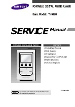
Samsung YH-820, Service Manual
The Samsung YH-820 is a cutting-edge portable media player offering an immersive multimedia experience. Unlock the full potential of this device with our comprehensive User Manual, available for free download from manualshive.com. Discover all the features and functionalities to enhance your entertainment on the go.
Share
Download


Reviews:
No comments
Related manuals for YH-820
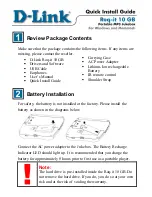
DMP-HD610
Brand: D-Link Pages: 5
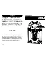
Jukebox with CD CR12-1
Brand: Crosley Pages: 6
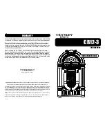
Crosley Full Size Jukebox CR12-3
Brand: Crosley Pages: 5
PJUB25BT
Brand: Pyle Pages: 4
Lyra PDP2860
Brand: THOMSON Pages: 40

10036452
Brand: auna Pages: 144
DMP-X
Brand: Gateway Pages: 104
Max Fire HD
Brand: TAB-Austria Pages: 53
RDJB3000BN
Brand: nedis Pages: 37
Lyra PDP2842
Brand: THOMSON Pages: 69
RR500
Brand: Ricatech Pages: 32
300955-001
Brand: Octave Pages: 22
JK 20-S
Brand: H&B Pages: 24
Home Music HD-1
Brand: Nokia Pages: 48
C1104 Series
Brand: HP Pages: 18
StorageWorks 1000ux
Brand: HP Pages: 80
StorageWorks 1100ux
Brand: HP Pages: 40
StorageWorks 3800ux
Brand: HP Pages: 82


