BN68-05629A-00
QUICK START
GUIDE
Welcome to your new Smart TV!
The following instructions cover assembling, connecting, and setting up your new TV. Make sure
you have the accessories listed below.
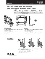
Included in this box
Step 1
Installing the
Wall Mount
Step 5
Power on and
start the initial
setup
Step 4
Using the
Smart Touch
Control
Step 3
Connect
devices
Step 2
Connect
Audio Devices
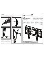
Step 1
Installing the Wall Mount
Installation Precautions
•
Use the provided accessories and parts to install the wall mount.
•
Install the product onto a flat wall surface only.
•
Avoid the following areas to ensure the best product performance and prevent malfunctions:
- Areas that are susceptible to vibration and impact: The TV might come loose from the mount
and be damaged.
- Next to fire sprinklers: Heat generated by the TV could activate the sprinkler.
- Near high-voltage cables: Electronic interference from the high-voltage cables may disrupt
the screen display.
- Near a heating appliance: The product may overheat and malfunction.
- Check the stability of the wall surface.
- If the wall is too weak, reinforce it before installing the mount.
•
Do not remove a section of the wall and install the mount there.
•
Plug all the cables into the correct ports and connectors before installing the wall mount.
•
If attempting to install the product onto a non-concrete wall, consult an installation specialist
first.
•
Once installed, the gap between the wall surface and the TV should be at least 31 mm.
•
For the types of walls the TV can be mounted on, check the model of your TV and then the
corresponding installation guide on the back of the product.
Wall Mount Accessories
✎
Use only the provided accessories and parts to install the wall mount.
A (4)
Mounting Piece
B (8)
M4 X 8
C (4)
M4 X 47
Wall Mount Brackets
Left: 1, Right: 1
Length Adjustment
Bars
Ø25 : 2
D (24)
M5 X 65
E (24)
Anchor
F (2)
M6 X 30
]
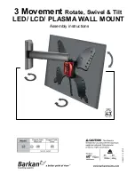
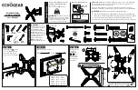
Check the type of the wall before installing.
Installation requirements for each wall type
•
Can only be mounted on a concrete or interior wall of sufficient thickness. Refer to the diagrams
below.
✎
NOTE
MDF = Medium Density
Fiberboard
PW = Plywood
Min. 50 mm
Min. 10 mm
Min. 30 mm
Min. 30 mm
Min. 10 mm
Min. 10 mm
Art Wall
Art Wall
MDF or PW
MDF or PW
MDF or PW
Concrete
MDF or PW
Min.
50 mm
Min.
25 mm
Min.
25 mm
With MDF
or plywood
reinforcement
MDF or PW
(Excluding
drywall thickness)
Composite
Concrete Wall
(Excluding
drywall thickness)
•
Installation is not possible on a drywall or on a wall with no internal reinforcement.
0~24 mm
Art Wall
Drywall
No internal
reinforcement
Cannot install directly on drywall.
MDF, PW, or Concrete
Also included: User manual, regulatory guide, IR extender,
component adapter, RCA adapter x 2, power cord, Ferrite core
Smart Touch Control &
Batteries (AAA x 2)
3D Glasses Accessories:
3D Active glasses, USB charge cable
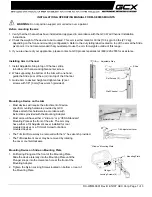
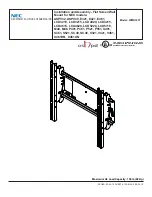
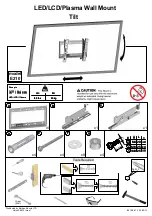
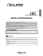
1
1-1
1-2
TV
wall
1-1
1-2
TV
wall
Object
Object
31mm
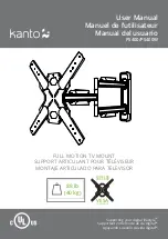
1-1.
If the wall is not flat, a gap may form
after the installation is completed and
this may result in a poor finish.
1-2.
The TV cannot be mounted on the wall
if there is an object between the TV and
the wall that is 31 mm or thicker.
Check the wall’s type, thickness, and flatness.
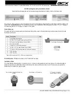
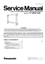
2
L
R
Check the L and R markings on the front sides of the wall mount brackets.
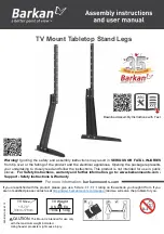
F
3
Drive the level adjustment screw into the hole to get it prepared for use.
B
4
Attach the length adjustment bars to the two wall mount brackets using screws.
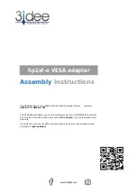
5
Place the assembly against the wall you wish to mount it on, and then mark the anchor insertion
points on the wall.
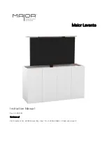
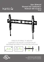
6
E
]
Installation on drywall with studs.
15mm
D
Insert the anchors and screws where marked.
Requirements
•
Verify the location of the studs first and use wall screws.
•
Minimum Stud Size: 51x102mm or 2x4 in (Drill 3mm holes before inserting wall screws).
•
Drill the holes along the central axis of the stud.
•
Inserting the screws without pre-drilling the holes can split the stud.
]
The manufacturer will not be held liable for any issue arising from failure
to comply with the instructions and requirements contained in this
installation guide.
D
7
Remove the screws that hold the wall mount brackets in place.
One Connect Accessories:
One connect, one connect cable
[UN85S9VF_QSG]BN68-05629A-00ENG.indb 2
2013-10-29 �� 1:25:40