background image

1. Installing the SVMi-20E in an OfficeServ 7200/7400 Series System

When installing an SVMi-20E card, it is important to remember that it is a computer, much the same as any
desktop PC and it is therefore very important not to exceed the environmental limits of an ordinary PC.

I

POWER REQUIREMENTS

Because the SVMi-20E card does NOT draw from the -48DC supply it has a Zero (0) SEPU rating under all
possible configurations.

I

OfficeServ 7200/7400 Series HARDWARE COMPATIBILITY

When configured for 16 ports or less this card can be installed in any universal slot. When configured for
20 ports the SVMi-20E card must be installed in 32 channel slots.

I

OfficeServ 7200/7400 Series SOFTWARE COMPATIBILITY

All versions of the OfficeServ 7200/7400 support the SVMi-20E operation. We have introduced a new 8-
Port VPM daughterboard to reach the 20 ports that requires SVMi-20E software version 5.3.3.5 or higher
and MP software version 4.30h or higher.

2. Inspection

Unpack and inspect the unit for any obvious damage. This card should be labeled SVMi-20E. If it is not, you
have the wrong card. Before inserting the SVMi-20E card in the OfficeServ system install required optional
boards to meet customer’s configuration and requirements.

3. Installing Individual Components on SVMi-20E SBC

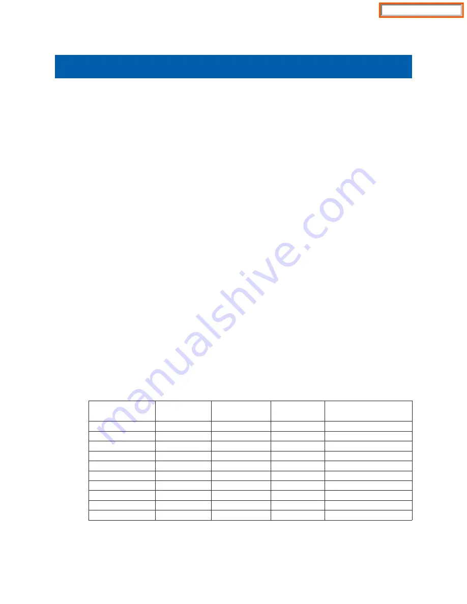
3.1 Installing Voice Processing Modules

VPMs are only necessary when more than 4 ports are required on the SVMi-20E.VPMs are NOT required
to access the first four embedded ports. Adding new VPMs is as simple as plugging them with the cor-
rect location for each module. Here is a chart showing the correct location and VPM for this installation.

SVMi-20E Installation / May 2009

1

SVMi-20E INSTALLATION

Configuration

Included on

SBC

VPM in SL2

VPM in SL3

Total Ports

1

4

none

none

4 Voice

2

4

VPM-E

none

8 Voice

3

4

VPMF-E

none

8 Voice Supporting 1 Fax

4

4

VPM-E

VPM-E

12 Voice

5

4

VPM-E

VPMF-E

12 Voice Supporting 1 Fax

6

4

8VPMF-E

none

12 Voice Supporting 1 Fax

7

4

VPMF-E

VPMF-E

12 Voice Supporting 2 Fax

8

4

8VPMF-E

VPM-E

16 Voice Supporting 1 Fax

9

4

8VPMF-E

VPMF-E

16 Voice Supporting 2 Fax

10

4

8VPMF-E

8VPMF-E

20 Voice Supporting 2 Fax

Home Page

Summary of Contents for SVMI-20E

Page 1: ...and inspect the unit for any obvious damage This card should be labeled SVMi 20E If it is not you have the wrong card Before inserting the SVMi 20E card in the OfficeServ system install required optional boards to meet customer s configuration and requirements 3 Installing Individual Components on SVMi 20E SBC 3 1 Installing Voice Processing Modules VPMs are only necessary when more than 4 ports a...

Page 2: ...he card seats The SVMi 20E card can now be installed in the KSU Once the SVMi 20E is securely seated in the OfficeServ 7200 7400 Series System the KSU can be powered up 3 2 Installing the Modem Daughter Board 3 2 1 PREPARATION If installing a Modem Daughter Board into an existing SVMi 20E installation the SVMi 20E MUST be shutdown properly MMC 746 and once down the OfficeServ 7000 Series System mu...

Page 3: ...s notched and the DRAM Module should be held a 45 to 25 degree angle when inserting into the connector Once inserted gently push down on the module until the notch es on either side edge snap into place Properly installed the DRAM module will lay virtually parallel to the main SVMi 20E PCB Follow the instruction in either the Installing a Hard Disk Drive or Installing the Compact Flash CF Adaptor ...

Page 4: ... If the SVMi 20E card is being installed in an existing not new system use MMC 806 to pre install the card and MMC 724 to assign extension numbers to each SVMi 20E port Use any available numbers After the SVMi 20E card is installed either in a new or existing system use MMC 601 and assign all the SVMi port numbers to the last available station group Group Number 5039 by default on the OfficeServ 7...

Page 5: ... remove the SVMi 20E card 3 Hold the unit with the CF Adapter supported in your hand held by the edges The solder side of the card should be facing up 4 Remove the 4 retaining screws so that the CF Adapter becomes detached 5 Still holding the CF Adapter by the edges invert the card component side up and gently unplug the ribbon cable 6 Gently pack the CF Adapter in the SEC provided packaging 6 2 I...

Page 6: ...er Also shown are the SVMi 20E Compact Flash Controller and 256MB Compact Flash Media The SVMi 20E on the right shows all the connectors unpopulated You can see with the CF Controller removed where the DRAM connector is located SVMi 20E Installation May 2009 6 SVMi 20E CF with all optional boards installed SVMi 20E with no optional boards installed Home Page ...

Page 7: ...g up it will also turn Green when the SVMi 20E is shut down properly It will turn Orange after the Voice Drivers are loaded into memory and then turn RED when the application Software is fully loaded RED is warning letting you know the aaplication is running and it is NOT safe to power down the OfficeServ 7200 7400 Series System 7 1 2 SYSTEM PROGRAMMING Review and perform the following programming...

Page 8: ...ng any future changes you make to the SVMi 20E database 7 1 4 TESTING THE HARDWARE 1 Call each SVMi 20E port individually and confirm that SVMi 20E answers 2 Call station group 5039 and confirm that SVMi 20E answers If steps 1 and 2 above proved to be successful you have completed the installation and setup of the SVMi 20E hardware You are now ready to begin programming the SVMi 20E Voice Mail Aut...

Page 9: ...ter a password enter the System Administrator s password Default 0000 7 The system will now shutdown to a C DOS Prompt The SDN LED will turn from RED to GREEN Green means it is safe to power down the switch Also if you are logged in via an SIO Terminal when the SVMi 20E terminal emulation screen shows a DOS command line this also means the SVMi 2OE is no longer processing and it is safe to power o...

Page 10: ...i 20E is connected 3 Set Bits per second to 38 400 4 Set Data Bits to 8 5 Set Parity to None 6 Set Stop Bits to 1 7 Set Flow Control to None 8 Click Properties 9 Click the Settings tab 10 Select Terminal keys 11 Set Emulation type to ANSI or ANSIW 12 Set Line Wrap to No When this is complete press Ctrl L two or three times to refresh the screen and you should see the SVMi 20E Status Screen You are...

Page 11: ...P address The default address is 10 10 108 6 For more information on this see additional Documentation on Back Up and Restore and FTP 9 2 1 LOCAL PROGRAMMING VIA LAN Connect the LAN port of the SVMi 20E unit directly to a PC via a RJ45 10 100baseT cat5 Crossover Cable Setting Up the Network Device on your PC or Laptop You need to consult your Operating Systems user s manual for how to set up a net...

Page 12: ... and be connected to the internet via one of the many available High Speed connec tions If they have a Dial Up internet connection this will not work Connect to the customer s internal Local Area Network LAN using a straight through RJ45 10 100baseT cat5 cable Use the same information above for Setting up your Network Device and Communications Software 9 2 4 CHANGING THE DEFAULT SVMi 20E IP ADDRES...

Page 13: ...r communicate with the SVMi 20E The 24 is the subnet mask reference 24 represents the number of consecutive ones in the subnet mask A typical subnet mask is 255 255 255 0 in binary it looks like 11111111 11111111 11111111 00000000 If you count the number of consecutive ones they equal 24 in this example 5 Next navigate so your cursor is to the right of the 5 in the route add default ip address and...

Page 14: ... A in front of a line in the Socket CFG file tells the application to ignore skip over and NOT execute the line Using SCONFIG SCONFIG EXE is a utility provided by the TCP IP software used for creating a SOCKET CFG file It will ask you a few questions that help you create the connections setting for the SVMi 20E to communicate on your network To use SCONFIG you must also be at a DOS c prompt as des...

Page 15: ...k card s IRQ This value is not optional The LAN controller on the SVMi 20E is set at IRQ 10 11 At this point the utility will inform you it is complete and that socket cfg has been created You can now restart the SVMi 20E normally After you change your Communications software to use the IP address you just pro grammed into the socket cfg file You should be able to login to the SVMi 20E from any wh...

Reviews: