SERVICE
THERMAL RECEIT PRINTER
CONTENTS
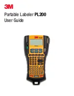
SRP-350
/350S/350P/350U
THERMAL RECEIPT PRINTER
Manual
1.
Precaution Statements
2.
Product Specification
3.
Installation and Operation
4.
Disassembly and Assembly
5.
Maintenance and Adjustment
6.
Reference Information
7.
Special Circuit Descriptions
8.
Troubleshooting
9.
Exploded Views and Parts List
10.
PCB Layout and Parts List
12. Block Diagram
13. Wiring Diagram
14. Schematic Diagrams
SRP-350
G/350SG/350PG/350UG
Commands
11.
SRP-350 Ver.2 Series
Summary of Contents for SRP-350U
Page 2: ...About Notes Precaution symbols Samsung Electro Mechanics ...
Page 4: ...Overview of this Receipt Printer Samsung Electro Mechanics ...
Page 7: ...1 Precaution Statements 8 6 0 A 6 8 9 8 4 8 8 1 3 Samsung Electro Mechanics ...
Page 8: ...1 Precaution Statements 1 4 MEMO Samsung Electro Mechanics ...
Page 26: ...2 Product Specifications 2 18 MEMO Samsung Electro Mechanics ...
Page 34: ...3 Installation and Operation 3 8 MEMO Samsung Electro Mechanics ...
Page 63: ...7 Special Circuit Descriptions 7 12 MEMO Samsung Electro Mechanics ...
Page 113: ...12 Block Diagram 12 2 MEMO Samsung Electro Mechanics ...
Page 115: ...13 Wiring Diagram 13 2 MEMO Samsung Electro Mechanics ...
Page 125: ... SAMSUNG ELECTRO MECHANICS Co Ltd January 2004 Printed in Korea ELECTRO MECHANICS ...