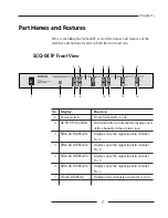
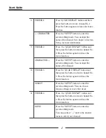
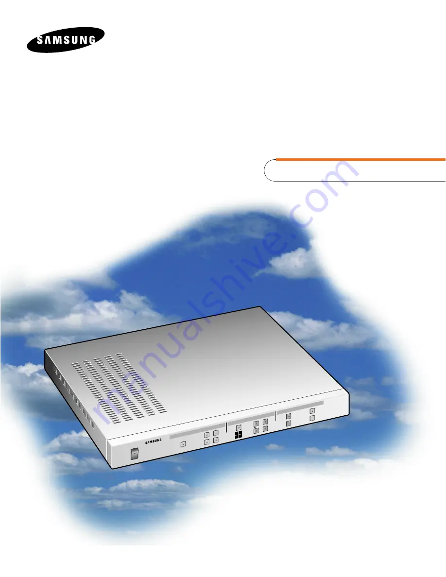
background image

Part  No.: AB68-00052A
Printed  in  Korea

SCQ-041P

User’s Guide

DIGITAL
COLO

R QUAD SW

ITCHER

SCQ-041P

POWER

CHA

RAC

TER

SELE

CT

MEN

U

SETU

P

ENT

ER

RES

ET

LIST

ON

OFF

AUTO SWITCHER

1

2

3

4

1

2

3

4

SINGLE DISPLAY

QUAD DISPLAY

FREEZE

SYSTEM SETUP

ALARM

1 2
3 4

DIGITAL COLOR QUAD 

SWITCHER

Summary of Contents for SCQ-041AP

Page 1: ...Guide DIGITAL COLOR QUAD SWITCHER SCQ 041P POWER CHARACTER SELECT MENU SETUP ENTER RESET LIST ON OFF AUTO SWITCHER 1 2 3 4 1 2 3 4 SINGLE DISPLAY QUAD DISPLAY FREEZE SYSTEM SETUP ALARM 1 2 3 4 DIGITALCOLORQUAD SWITCHER ...

Page 2: ...Part No AB68 00052A Printed in Korea ...

Page 3: ...iii SAFETY PRECAUTIONS WARNING To Reduce the risk of fire or electric shock do not expose this appliance to rain or moisture ...

Page 4: ...be adhered to 4 Follow instructions All operating and use instructions should be followed 5 Cleaning Unplug this video product from the wall outlet before cleaning Do not use liquid cleaners or aerosol cleaners Use a damp cloth for cleaning 6 Attachments Do not use attachments not recommended by the video product manufacturer as they may cause hazards 7 Water and moisture Do not use this video pro...

Page 5: ...vided for ventilation and to ensure reliable operation of the video product and to protect it from overheating and these openings must not be blocked or covered The openings should never be blocked by placing the video product on a bed sofa rug or other similar surface This video product should never be places near or over a radiator or heat register This video product should not be placed in a bu...

Page 6: ...t the cable system This will prevent damage to the video product due to lightning and power line surges 13 Overloading Do not overload wall outlets and extension cords as this can result in a risk of fire or electric shock 14 Object and liquid entry Never push objects of any kind into this video product through openings as they may touch dangerous voltage points or short out parts that could resul...

Page 7: ... and will often require extensive work by a qualified technician to restore the video product to its normal operation e If the video product has been dropped or the cabinet has been damaged f When the video product exhibits a distinct change in performance this indicates a need for service 17 Replacement parts When replacement parts are required be sure the service technician has used replacement ...

Page 8: ...hould read this guide carefully before using the product even if you have worked with the same level of SCQ 041P to ensure the products are properly used according to the instructions on the back of this guide It is important to contact the supplier to receive technical assistance from an expert when you need to open the system cover and work inside the system to expand or repair the SCQ 041P feat...

Page 9: ...041P system and describes the features and characteristics of the system as well as part names and feature buttons Chapter 2 SCQ 041P Installation Describes the SCQ 041P configuration cautions to be observed during installation and how to unpack the system Chapter 3 Connecting Other Components Describes how to connect the SCQ 041P system with a camera a monitor and a VCR Chapter 4 Configuring the ...

Page 10: ...criptions such as SCQ 041P component specifications and a detailed illustration of the system exterior Appendix B Remote Control Connector Table describes the RS 232C cable pin connection and various keys on the PC keyboard used for remote control Appendix C Troubleshooting describes what to check and troubleshoot if any system problems are encountered ...

Page 11: ...g a VCR 13 Connecting a Monitor 14 Connecting an Alarm 15 Connecting External Components 15 Chapter 4 Configuring the SCQ 041P 16 24 Channel Title Setting 17 Date Time Setting 19 Display Mode Setting 20 Alarm Setting 21 Auto Switcher Setting 23 Loss Dettect Setting 24 Chapter 5 Operating the Alarm 25 29 Alarm Input Output Terminal Specification 25 Alarm Signal Mode 26 Viewing the Alarm List 27 Sea...

Page 12: ...nnel LOSS Search in Each Mode 30 Restoring to Normal Mode 31 Appendix A SCQ 041P Specifications 32 34 Specifications 32 External Components 34 Appendix B Remote Control Connector Table 35 36 RS 232C Table 36 Terminal Components 36 Appendix C Troubleshooting 37 ...

Page 13: ...vidual image produced by inputting four video image signals such as a CCTV camera The SCQ 041P displays a maximum of eight alpha numeric characters in corresponding to the title of the channel on the connected monitor screen The SCQ 041P also provides other various features such as time display external alarm signal and remote control for wide system service ...

Page 14: ...reeze in quarter screen mode using FREEZE button When an alarm is on the screen displays the alarm signal and the relevant channel If several alarms are on the screen converts itself to the quarter screen display feature automatically to control many channels simultaneously The channel loss feature provides a buzzer sound and displays the channel loss on the screen You can use the remote control f...

Page 15: ...INGLE DISPLAY 1 Displays only the signal input in channel No 1 4 SINGLE DISPLAY 2 Displays only the signal input in channel No 2 5 SINGLE DISPLAY 3 Displays only the signal input in channel No 3 6 SINGLE DISPLAY 4 Displays only the signal input in channel No 4 7 QUAD DISPLAY Displays four channels on quarter screen DIGITAL COLOR QUAD SWITCHER SCQ 041P POWER CHARACTER SELECT MENU SETUP ENTER RESET ...

Page 16: ... function CHARACTER Press the SETUP button to enter the system setting mode You can input the name of the channel 10 FREEZE 3 Press the QUAD DISPLAY button and then press the button to freeze channel No 3 Press the button again to release the freeze function SELECT Press the SETUP button to enter the system setting mode You can choose various settings or move the cursor 11 FREEZE 4 Press the QUAD ...

Page 17: ... this button to move between the main menu and the sub menu 14 RESET When the alarm sounds or a channel is lost a green light appears on the button Press the button to disable the alarm however you cannot turn off the green LED light in the case of a channel loss 15 LIST You can check eight of alarm information or channel loss information in the order in which they were generated NOTE You can find...

Page 18: ... by connecting output connector of camera to CH3 4 VIDEO INPUT CH4 Input signal by connecting output connector of camera to CH4 5 VIDEO OUTPUT 1 You can view quarter screen by connecting the output signal to a monitor or video input connector 6 VIDEO OUTPUT 2 You can view quarter screen or single screen or automatic sequence screen by connecting output signal to a monitor or video input connector ...

Page 19: ... be connected to the Alarm Reset Input terminal of a external unit such as time lapse VCR 8 RS 232C You can control the SCQ 041P remotely by connecting the remote control connector to a PC with a terminal emulation program using an RS 232C cable 9 AC IN This is an input terminal that connects to AC 100V 240V power NOTE The above connectors 1 to 4 are 75 automatic terminal resistance Therefore this...

Page 20: ...ration please make sure to allow enough ventilation in the system operating room and fix the cover of main unit firmly High voltage current occurs in the unit therefore please do not try to open the cover The SCQ 041P requires the following operating conditions to maintain temperature and humidity Operating temperature 32 86 F 0 40 C Relative humidity 30 90 relative humidity Input voltage AC 100V ...

Page 21: ...g to install the system Please check the contents of the package as listed below SCQ 041P MAIN UNIT USER S GUIDE POWER CABLE 1 EA 19 inch RACK MOUNT ADAPTOR 2 EA DIGITAL COLOR QUAD SWITCHER SCQ 041P POWER CHARACTER SELECT MENU SETUP ENTER RESET LIST ON OFF AUTO SWITCHER 1 2 3 4 1 2 3 4 SINGLE DISPLAY QUAD DISPLAY FREEZE SYSTEM SETUP ALARM 1 2 3 4 ...

Page 22: ...ally tighten the screws so that they are holding the adaptor loosely in place 4 Adjust the mounting adaptor the front of the adaptor is flush with the front panel of the SCQ 041P enclosure 5 Tighten the mounting screws so that the adaptor is firmly attached to the SCQ 041P enclosure Be careful not to over tighten the screws 6 Repeat the procedure described above to attach the remaining adaptor to ...

Page 23: ...o the SCQ 041P align the SCQ 041P within the appropriate space in the rack and attach it firmly to the rack Warning Install the SCQ 041P on the Rack with a minimum distance between the SCQ 041P and the other system of at least 22mm a half of the SCQ 041P height ...

Page 24: ...ts to the SCQ 041P This chapter describes how to connect these components CAUTION Please do not supply over 2V DC to the VIDEO INPUT CH1 VIDEO INPUT CH2 VIDEO INPUT CH3 or VIDEO INPUT CH4 input terminals Connecting a Camera CH1 IN OUT CH2 IN OUT CH3 IN OUT CH4 IN 1 2 OUT VIDEO INPUT VIDEO OUTPUT Camera 1 Camera 2 Camera 3 Camera 4 ...

Page 25: ...hapter 3 13 Connecting a VCR CAUTION Connect monitor and VCR separately to both of VIDEO OUTPUT connectors CH1 IN OUT CH2 IN OUT CH3 IN OUT CH4 IN 1 2 OUT VIDEO INPUT VIDEO OUTPUT VIDEO INPUT VIDEO INPUT ...

Page 26: ...een NOTE What is Auto Switcher Mode This feature allows the unit to switch a single screen from four channels in sequence But when the channel VIDEO LOSS happened or is set to interval time of AUTO SWITCHER SET as 0 It is skipped CHANNEL LOSS or it is set to interval time of all channels as 0 of AUTO SWITCHER SET it is converted quad screen CH1 IN OUT CH2 IN OUT CH3 IN OUT CH4 IN 1 2 OUT VIDEO INP...

Page 27: ...NPUT ALARM OUT CH1 2 3 4 OUT GND GND 1 2 3 4 RESET Time Lapse VCR Alarm unit Sensor CH1 IN OUT CH2 IN OUT CH3 IN OUT CH4 IN 1 2 OUT VIDEO INPUT VIDEO OUTPUT 1 2 3 4 Monitor 1 Quarter screen display mode Camera External Components Monitor 2 Quarter screen Auto switching or single screen display mode ...

Page 28: ...e system on 2 Press the SETUP button and the green light over the LED on the button come on Now you can see the system setup main menu on the quarter section screen as illustrated below If you press the MENU button located on the front of the system you can move the mark If you press the SETUP button the main menu disappears and the LED light simultaneously goes off You can then return to the prev...

Page 29: ...CHANNEL TITLE SET Then press the ENTER button to show the sub screen for setting a channel title as shown below At this point you can enter letters on the position of the blinking cursor Move the position of by pressing the MENU button Move the position of the cursor by pressing the SELECT button A letter to be entered on the position of the cursor can be selected by pressing the CHARACTER or CHAR...

Page 30: ...le above Press the CHARACTER button to select a letter to be on the right out of the Character Table above After completing the setup of each channel title press the ENTER button Then the main menu appears If you want to proceed the system setup for another item move to a desired menu When all the required setups are done press the SETUP button to exit the system setup mode ...

Page 31: ... the character at the blinking cursor To move use the MENU button To move the cursor use the SELECT button in 2 DATE and 3 TIME Press the SELECT button to choose the preferred date format in 1 DATE DISPLAY mode Press either the CHARACTER or CHARACTER button to change the value s in 2 DATE and 3 TIME If you press the CHARACTER button you can choose the next lower number If you press the CHARACTER b...

Page 32: ...en and title display type using 3 DISPLAY MODE SET In the main menu press the MENU button to move next to 3 DISPLAY MODE SET and then press ENTER button again to display the following sub menu To move press the MENU button The following is description of the four items in DISPLAY MODE SET 1 CHANNEL AND TIME Displays the name of the channel and the time 2 CHANNEL ONLY Displays only the name of the ...

Page 33: ...s Press the SETUP button if you are finished with the menu Alarm Setting If you are not in the system setup mode press the SETUP button to enter the system setup mode If an alarm signal is present in the ALARM input terminal in the back of the system the character A is displayed on the screen The screen also shows the channel alarmed with the alarm When you input more than two signals you can view...

Page 34: ...larm feature on while the alarm is on Following are the alarm time intervals 05 seconds 10 seconds 20 seconds 30 seconds 60 seconds 90 seconds 120 seconds 180 seconds Manual NOTE When M manual is selected the alarm is armed only when the alarm signal input level is LOW in the TTL level When you finish setting the alarm mode press ENTER button to return to the main menu If you want to continue with...

Page 35: ...r each channel by using the CHARACTER or CHARACTER button For example if the time interval for each channel is set to 5 automatically each channel is displayed on the screen for 5 seconds in turn If the time interval of a channel is set to 0 or when a video loss of a channel occurs the corresponding channel will be skipped to the next channel when the AUTO SWITCHER is selected After completing the...

Page 36: ...wn below Move the position of by pressing the MENU button Set ON or OFF for each channel by using the SELECT button The channel with OFF setting the CHANNEL LOSS DETECT will not be carried out After completing all the setups of LOSS DETECT SET press the ENTER button to show the main menu If you want to proceed the setup for another item move to a desired item for the setup When all the required se...

Page 37: ...ifications and how to view the alarm list Alarm Input Output Terminal Specification The following figure shows the alarm input output terminal in the back of the system Alarm input terminal 4 EA Alarm input GND 4 EA Alarm output terminal 1 EA Alarm reset output 1 EA Alarm output reset GND 1 EA ALARM IN OUT ALARM INPUT ALARM OUT CH1 2 3 4 OUT GND GND 1 2 3 4 RESET ...

Page 38: ... is off The alarm reset output mode produces the above signal mode when all alarms are off When several alarms are on at the same time ALARM RESET OUTPUT maintains the TTL LOW level for 150 mS and then returns to TTL HIGH level ALARM IN 1 ALARM IN 2 ALARM IN 3 ALARM IN 4 ALARM OUT ALARM RESET EVENT OCCURS EVENT OCCURS ALARM 2 ALARM 3 ACTION ALARM 3 ALARM 4 ACTION ALARM 1 ACTION ALARM 3 ACTION More...

Page 39: ...e the displayed data press and hold the both of the AUTO and RESET buttons for about 2 seconds Then all the data of alarm and channel loss will be erased NOTE You cannot use the LIST button when the alarm or the system setup mode is on ALARM LOSS LIST YY MM DD HH MM SS 1 99 03 26 20 10 24 4 L 2 99 03 26 12 19 34 3 A 3 99 03 26 08 49 58 3 L 4 99 03 26 08 40 02 1 L 5 99 03 26 08 31 26 2 A Occurrence...

Page 40: ... Then the screen displays the latest mode before the system setup mode Each channel s alarm functions individually During time the alarm is on most features are restricted except the RESET button SINGLE DISPLAY buttons and QUAD DISPLAY button Situations in which the Alarm is in Use The following describes the sequence of events when the alarm is on 1 The screen displays the channel for which the a...

Page 41: ...on to disable the alarm manually 8 When the alarm is disabled the alarm output becomes TTL HIGH level 9 When the alarm is disabled the alarm reset output is maintained for 150ms and then becomes TTL HIGH level 10 The date hour and channel number of the relevant alarms are recorded in the alarm list NOTE Press the LIST button to scan this information 11 When the alarm is disabled the screen display...

Page 42: ...Y button the buzzer is on and the lost channel number is on at the bottom of the screen When you press the button corresponding to the lost channel number the screen becomes blue and the number of the lost channel is indicated In auto switcher display mode when you press the AUTO SWITCHER button the buzzer is on Then when the screen changes the lost channel number is on at the bottom of the screen...

Page 43: ...g to Normal Mode If you input the normal channel signal after channel LOSS occurs the system senses the signal automatically and returns to the formal mode If you turn off the channel that shows LOSS in the 6 LOSS DETECT SET menu the channel LOSS terminates so that the screen reverts to the normal mode ...

Page 44: ...screen display options 1 0 V p p 75 Alarm Feature Input 4EA TTL LOW level active Output 2EA TTL LOW level active Alarm duration 5 seconds to 180 seconds M manual user must set alarm duration in the menu Auto Switcher Time for auto switcher 0 to 30 seconds User must set time in the menu You can turn the Auto Switcher ON or OFF for each channel Remote Control Remote control is available by using an ...

Page 45: ...and time year month day hour minute second Alarm indication A Channel Loss LOSS Operating Configuration Operating temperature 32 86 F 0 40 C Relative humidity 30 90 relative humidity Power voltage AC100V 240V Power consumption 10 Watts Frequency 50 Hz 60 Hz Weight 8 4 lb 3 8 Kg Dimensions 430 W mm 44 H mm 350 D mm 33 ...

Page 46: ...U SETUP ENTER RESET LIST ON OFF AUTO SWITCHER 1 2 3 4 1 2 3 4 SINGLE DISPLAY QUAD DISPLAY FREEZE SYSTEM SETUP ALARM 1 2 3 4 430 mm 350 mm 44 mm CH1 IN OUT CH2 IN OUT CH3 IN OUT CH4 IN 1 2 OUT VIDEO INPUT VIDEO OUTPUT RS 232C AC IN ALARM IN OUT ALARM INPUT ALARM OUT CH1 2 3 4 OUT GND GND 1 2 3 4 RESET ...

Page 47: ...e control of the SCQ 041P PIN NO CONTROL ITEMS FUNCTION 1 FG FRAME GROUND 2 TXD TRANSMITTED DATA 3 RXD RECEIVED DATA 7 SG SIGNAL GROUND 11 13 14 GND 4 6 8 10 NO CONNECTION 12 15 25 35 1 2 3 4 5 6 7 8 9 10 11 12 13 14 15 16 17 18 19 20 21 22 23 24 25 Operation depends on various functions of RS 232C ...

Page 48: ...ing table shows relation between the PC keyboard and the feature buttons of SCQ 041P Keyboard Key ASCII Function A AUTO SWITCHER R ALARM RESET E ENTER Q QUAD DISPLAY L LIST S SETUP 1 SINGLE DISPLAY 1 2 SINGLE DISPLAY 2 3 SINGLE DISPLAY 3 4 SINGLE DISPLAY 4 5 FREEZE1 CHARACTER 6 FREEZE2 CHARACTER 7 FREEZE3 SELECT 8 FREEZE4 MENU Terminal components Baud rate 9600 bps Data bits 8 Stop bit 1 Parity no...

Page 49: ...other components If the Function buttons in the front of the system are not working Check if the current mode is the alarm mode If you cannot convert the quarter screen display to single screen display Check whether the monitor cable is connected to the QUAD ONLY OUTPUT terminal marked with from the output terminals in the back of the SCQ 041P If the problem persists after taking the actions descr...

Reviews: