Samsung SCP-2271/SCP-2271H, User Manual
Looking for a reliable surveillance camera? Check out the Samsung SCP-2271/SCP-2271H! Capture high-quality footage with ease using this advanced camera. Ensure optimal usage by referring to the User Manual, available for free download on our website. Simply visit manualshive.com and unlock the full potential of your new Samsung SCP-2271/SCP-2271H.
Share
Download


Reviews:
No comments
Related manuals for SCP-2271/SCP-2271H

DCC-608DV
Brand: D-MAX Pages: 8

DND7220 Series
Brand: Digimerge Pages: 20

DS-2CC592 P(N)-FB
Brand: HIKVISION Pages: 6

15-CD521W
Brand: COP Security Pages: 27

EX40N
Brand: Bosch Pages: 37

D2252DIR SERIES
Brand: Digital Watchdog Pages: 13
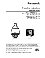
WV-SW396
Brand: Panasonic Pages: 244
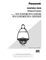
WV-SW396
Brand: Panasonic Pages: 40
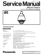
WV-SW396
Brand: Panasonic Pages: 61

HD820
Brand: avertX Pages: 48

scd-2080p
Brand: Samsung Pages: 2

scd-2080p
Brand: Samsung Pages: 19

P8220
Brand: Zavio Pages: 46

RC3502SV-7311IR
Brand: Riva Pages: 26

AXIS P3304-V
Brand: Axis Pages: 58

HSGI-H7DxF3S22
Brand: Hitron Pages: 25

RC3502HD-5211
Brand: Riva Pages: 11

RC2103HD-6511
Brand: Riva Pages: 29


