Samsung RW51TS338SR/AA, Installation Manual
The Samsung RW51TS338SR/AA installation manual is a comprehensive guide designed to assist users in setting up and operating their appliance. This user-friendly manual can be easily accessed and downloaded for free from manualshive.com, ensuring a hassle-free installation experience.
Share
Download


Reviews:
No comments
Related manuals for RW51TS338SR/AA
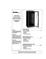
Designer DWC610BL
Brand: Danby Pages: 17
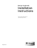
Monogram ZDBI240
Brand: GE Pages: 8
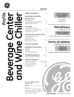
Profile PCR06WATSS
Brand: GE Pages: 64
JQ-332A
Brand: Haier Pages: 8
JQ-332A
Brand: Haier Pages: 8
JC-298G
Brand: Haier Pages: 6
HWS116GAE
Brand: Haier Pages: 98
Monogram ZDWI240
Brand: GE Pages: 8
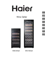
WS120GA
Brand: Haier Pages: 98
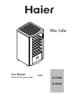
JC-110GD
Brand: Haier Pages: 14
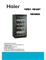
HWC-298SWA
Brand: Haier Pages: 18
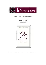
LS40
Brand: La Sommeliere Pages: 21
RW51TS338SR/AA
Brand: Samsung Pages: 64

PC200
Brand: Waring Pages: 8
EF24LWCZ1SS
Brand: Dacor Pages: 8
EF24LBCSS
Brand: Dacor Pages: 16
Wine Steward/Beverage Cooler
Brand: Dacor Pages: 12
DWC040A3BSSDD
Brand: Danby Pages: 2


