background image

PLASMA DISPLAY TV

Chassis : 

D54B(N)

Model:

PDP4294X/SMS

PLASMA DIAPLAY TV

C O N T E N T S

Specifications

Alignment and Adjustments

Exploded View and Parts List

Electric Parts List

Circuit Description

Troubleshooting

Schematic Diagrams

1.

2.

3.

4.

5.

6.

7.

Summary of Contents for P

Page 1: ...Chassis D54B N Model PDP4294X SMS PLASMA DIAPLAY TV CONTENTS Specifications Alignment and Adjustments Exploded View and Parts List Electric Parts List Circuit Description Troubleshooting Schematic Diagrams 1 2 3 4 5 6 7 ...

Page 2: ...g Electronics Co Ltd JUL 2003 Printed in Korea AA82 00793A This Service Manual is a property of Samsung Electronics Co Ltd Any unauthorized use of Manual can be punished under applicable International and or domestic law ...

Page 3: ...steps 1 and 2 above 2 1 2 Initial DISPLAY State of SERVICE MODE 2 1 2 A OSD DISPLAY 2 1 2 B Button Operations in SERVICE MODE 1 UPD64083 COMB FILTER 2 VPC3230 M MAIN VCD 3 VPC3230 S SUB VCD 4 FLI2200 DEINTERLACER 5 ASI500 I SCALER MAIN OSD 6 ASI500 II SCALER PIP 7 DNIe PICTURE ENHANCER 8 CXA2151HD COMPONENT MUX 9 AD9883 A D CONVERTER 10 LOGIC PDP DRIVER 11 TP LOG ASI TEST PATTERN 12 OPTION TM_ALS4...

Page 4: ...6 3 9 Component1 2 HD PC DVI ITEM CONTRAST BRIGHTNESS PEAKING CORING LUMA DELAY HPLL SPEED YUV CONTRAST YUV BRIGHTNESS YUV SATCB YUV SATCR YUV TINT SATURATION TINT TV VIdeo S Video Component1 2 SD 43 27 5 0 255 1 29 68 42 42 3 2000 32 43 27 5 0 255 1 29 68 42 42 3 2000 32 Component1 2 HD PC DVI 2 1 3 B VPC3230 TV COMP 43 27 5 0 255 1 29 68 42 42 3 2000 32 43 27 5 0 255 1 29 68 42 42 3 2000 32 ...

Page 5: ... YUV BRIGHTNESS LUMA DELAY H POSITION V POSITION TV VIdeo S Video Component1 2 SD 43 27 29 68 255 0 0 Component1 2 HD PC DVI 43 27 29 68 255 0 0 43 27 29 68 255 0 0 43 27 29 68 255 0 0 ITEM Y CLAMP C CLAMP Y DELAY C DELAY MOTION DETECT TV VIdeo S Video Component1 2 SD 0 512 4 11 48 Component1 2 HD PC DVI 0 512 4 11 48 0 512 4 11 48 0 512 4 11 48 ...

Page 6: ...ILTER MC FILTER UC FILTER LC FILTER YPASS R GAMMA G GAMMA B GAMMA H POSITION V POSITION H SIZE V SIZE OVERSCAN B OVERSCAN G OVERSCAN R TV VIdeo S Video Component1 2 SD 32 32 32 0 0 0 1 7 0 0 0 16 0 0 0 32 32 32 0 0 0 0 63 63 63 Component1 2 HD PC DVI 32 32 32 0 0 0 1 7 0 0 0 16 0 0 0 32 32 32 0 0 0 0 63 63 63 32 32 32 0 0 0 1 7 0 0 0 16 0 0 0 32 32 32 0 0 0 0 63 63 63 32 32 32 0 0 0 1 7 0 0 0 16 0...

Page 7: ...onent1 2 HD PC DVI 32 32 32 0 0 0 0 0 0 0 32 32 32 0 0 0 0 0 0 0 32 32 32 0 0 0 0 0 0 0 2 1 3 G DNIe ALL EXCEPT SUB BRIGHT CONT ITEM SUB BRIGHT SUB CONT NR SCALE MAX NR SCALE MIN DE GAIN COR DE GAIN CLIP CE UPPER CE CUTOFF CE GAIN WTE Y THRE WTE C THRE SYNC MODE PATT SEL TV VIdeo S Video Component1 2 SD 0 0 52 18 3 60 240 64 48 230 2 1 0 Component1 2 HD PC DVI 0 0 48 16 3 60 240 64 48 230 2 1 0 0 ...

Page 8: ...IN YG GAIN TV VIdeo S Video Component1 2 SD 1 7 7 1 1 7 7 1 Component1 2 HD PC DVI 2 1 3 H CXA2151HD COMP PC 1 7 7 1 1 7 7 1 2 1 3 I AD9883 COMP PC ITEM R GAIN G GAIN B GAIN R CR OFFSET G Y OFFSET B CB OFFSET AUTO COLOR TV VIdeo S Video Component1 2 SD 142 142 142 60 48 64 Component1 2 HD PC DVI 142 142 142 60 48 64 142 142 142 54 54 54 142 142 142 54 54 54 AUTO COLOR Automatic white balance adjus...

Page 9: ...M NOISE DIFF FILTER APC APC SET APC VALUE ACTIVE VPOS ACTIVE HPOS VSYNC POS HSYNC POS VSYNC WIDTH HSYNC WIDTH TV VIdeo S Video Component1 2 SD 140 130 120 0 0 0 1 0 2 0 1 1 0 127 12 19 3 32 2 12 Component1 2 HD PC DVI 140 130 120 0 0 0 1 0 2 0 1 1 0 127 12 19 3 32 2 12 140 130 120 0 0 0 1 0 2 0 1 1 0 127 12 19 3 32 2 12 140 130 120 0 0 0 1 0 2 0 1 1 0 127 12 19 3 32 2 12 ...

Page 10: ...mponent1 2 SD 0 0 1 1 4 4 4 0 0 0 0 10 0 0 0 1 21 16 Component1 2 HD PC DVI 0 0 1 1 4 4 4 0 0 0 0 10 0 0 0 1 21 16 0 0 1 1 4 4 4 0 0 0 0 10 0 0 0 1 21 16 0 0 1 1 4 4 4 0 0 0 0 10 0 0 0 1 21 16 Adjustment 0 OFF 1 RF Video S Video Component1 2 2 PC 3 ALL 0 minute 1 second Number of pixels that shift left right Number of lines that shift up down Time set during shift test Shift range Shift range 0 Ko...

Page 11: ...djust the gain of AD9883 the Highlight W B does not need to be adjusted since its deviation falls within valid distribution range PC adjustment is same as DTV adjustment The offset can be applied to the values obtained through DTV adjustment However additional adjustment is required for Y Cb and Cr of DTV since PC processes R G and B signals RF adjustment is performed with the Toshiba pattern in h...

Page 12: ...de DVI DTV COMPONENT 480P 720P 1080i PC VIDEO H L x 285 285 290 285 y 290 290 305 300 Y fL 32 0 33 0 17 6 33 0 L L x 285 285 290 285 y 295 290 300 295 Y fL 1 3 1 2 1 0 1 4 Pedestal Level Low Light measure point High Light measure point Pattern Used in Adjustment 10 Steps Gray scalepattern ...

Page 13: ...djusts voltage CN804 CN800S CN801 CN803 CN802 N805 N806 N812 T VS T Test Point T VSCAN T VSET T VA T VG T STB_5V T VE VR4 VSET VR6 VSCA N VR5 VE VR1 VS VR7 VA VR3 D5V VR2 Vstb VR Variable Resistor SMPS OUTPUT Voltage V VA See the labels attached on the base chassis VSCAN VSC VS VE VSET D5V 5V STB_5V 5V VG 15V ...

Page 14: ...2 12 Samsung Electronics MEMO ...

Page 15: ...w Driver Y P ulse Generator Column Driver X P ulse Generator Power Supply AC Power Source 110 220V LVDS Display Data Driver Timing Scan Timing A D Converter Image Scalar Micom Image Enhancer LOGIC B d ANAL OG B d POWER B d B d B d clock 60MHz clock 27MHz clo ck 20MHz 40MHz DIGITA L B d Video Decod er Deinterla c er TMDS Receiver Video S W Audio Processo r Comb Filter SUB Tuner MAIN Tuner Y Driver ...

Page 16: ...Circuit Operation Description 5 2 Samsung Electronics 5 2 WIRE DIAGRAM ...

Page 17: ...Circuit Operation Description Samsung Electronics 5 3 5 3 POWER SUPPLY 5 3 1 Block Diagram 95V 110V 78V MAG AMP 85 ...

Page 18: ...4 VAC The power supply must be able to start up under peak loading at 90V AC The power supply shall auto matically recover from AC power loss Note that nominal voltages for test purposes are considered to be with 1 0V of nominal STD_5V is a SELV standby voltage that is always present when AC mains voltage present 3 OUTPUT This power supply is 15 output switching power supply for PDP 42inch Alexand...

Page 19: ... 2 Short Circuit and Over current Protection Short circuit of the output terminal is defined as an output impedance that is less than 300mohm For a given SMPS when a VS output is short circuited the SMPS stops operation Even if a short circuit occurs between the main output and the STD_5V the SMPS does not fail When the short circuit is cleared it will operate normally again Even if a short_circui...

Page 20: ...r compensation circuit so that the power factor can be more than 0 9 Protection The SMPS has circuits which protect the product from over current over voltage and short circuit 5 Part Block Diagram and Part Function AC DC Converter The AC DC Converter converts AC input into DC voltage using a power factor enhancement circuit It is designed to not only enhance the power factor but also suppress noi...

Page 21: ...ined by the values of Rt and Ct in the circuit These values also determine the oscillation wave tilt and the off time of frequency Osillation frequency is obtained using the following formula fosc tRAMP Ct x Rt x 0 51 fosc 59 417kHz Rt R59 1 8W 20K Ct C14 MLCC 222 1 tRAMP 1 2 2 20 051 nF k In the SMPS circuit the oscillation frequency is as follows ...

Page 22: ...tand By voltage When the ON signal is activated from the remote control the main power supply of the SMPS starts operation Picture 3 Standby flyback Pulse Implementation of Sustain Voltage As the main part of a SMPS for PDP sustain voltage must supply a high power 85V 5 0A To comply with the specification the Asymmetrical Half Bridge converter method was used At the output stage two 85V converters...

Page 23: ...Circuit Operation Description Samsung Electronics 5 9 Picture 4 VS Drive FET SPW17N80C3 Drain pulse Picture 5 VS Drive FET SPW17N80C3 Gate pulse ...

Page 24: ...ntion to The PWM component is synchronized with the PFC component mentioned above In Current Mode Operations a PWM wave is induced via a current detection resistor or current transformer and indicates the current that flows through the output terminal DC DC Converter Input to VSCAN VSET and VE are included in the VS component Picture 6 VSET Pulse Picture 7 VE Pulse ...

Page 25: ...Circuit Operation Description Samsung Electronics 5 11 Picture 8 VSCAN Pulse Picture 9 VA Main Pulse Output VA Multi Outputs Pulse ...

Page 26: ...Circuit Operation Description 5 12 Samsung Electronics Picture 10 Multi Outputs Main Pulse ...

Page 27: ...T SYM 1 AC L 2 AC N CN800 AC INPUT NO OUTPUT SYM 1 5 0V D5V 2 15V VG 3 RTN 4 RTN 5 110V VE 6 RTN 7 RTN 8 85V VS 9 85V VS CN804 SX NO OUTPUT SYM 1 6V 2 RTN 3 3 3V D3 3V 4 3 3V D3 3V 5 RTN 6 RTN 7 12V D12V 8 PS_ON 9 RTN 10 5V STD_5V 11 THER_D CN802 D DIGITAL NO OUTPUT SYM 1 3 3V D3 3V 2 3 3V D3 3V 3 RTN 4 RTN 5 5V D5V 6 RTN 7 8 9 VS_ON 10 RTN CN803 LOGIC CN805 SY NO OUTPUT SYM 1 5 0V D5V 2 15V VG 3 ...

Page 28: ...tion Description 5 14 Samsung Electronics 5 3 4 Power Supply Systematic Diagram and Wiring Diagram 4 45 PDP 4 2inch ALEXANDER 4 2 P SP D44 1 F0 1 A 2 45 FAN LOGIC D ANALOG D DIGIT AL X boar d Buffe r Y Boar d INLET ...

Page 29: ...Layout CN804 CN8 0 3 CN8 0 2 CN8 1 1 CN806 CN8 0 5 CN8 0 1 T 1 S T 2 S T 8 S T 4 S T 5 S T 7 S T 6 S T 3 S HS1 HS2 HS3 CN8 0 0 CN812 CN8 0 7 CN8 0 8 CN8 0 9 CN8 1 0 V A A6V A 12V 12V AMP VT D3 3V D5V D3 3V D6V D 12V STD _5V D 12V D5V V G VS VE VSCA N V SET P RIMARY SECONDARY ...

Page 30: ...mal Abnormal Check the IC2 D28 PFC Normal Abnomal Check the IC1 Q1 Q2 Power ON VA Multi Check the IC35 Abnormal Abnormal Check the IC7 Normal VS Normal Abnormal Check the Q6 Q8 VSCAN VE VSET Abnormal Check the IC16 IC17 IC18 Normal Check the Other board Image Board or Driver Board or Cable ...

Page 31: ...40V 3 5A SHARP D5V chopper regulator BD1 BD3 D15XB60 600V 15A SHINDENGEN Bridge Diode D10 RHRP1 560 600V 15A FAIRCHILD PFC Diode D41 D42 KCF16A60 600V 16A NIHON INTER VS Output Diode D28 D2S4M 40V 2A SHINDENGEN V5SB Output Diode D37 KCF16A60 600 16A NIHON INTER VA Output Diode D209 D10LC20U 200V 10A SHINDENGEN 12VAMP Output Diode D203 D10LC20U 200V 10A SHINDENGEN A12V D12V Output Diode D205 MBR201...

Page 32: ...ress and sustaining sections is most widely used to generate the drive pulse Discharges conducted within PDP pixels using this method can largely be classi fied into 3 types as follows 1 Address discharge This functions to generate wall voltage within pixels to be lighted by addressing information to them i e impressing data voltage 2 Sustain discharge This means a display section where only pixel...

Page 33: ...egative wall charge The address discharge serves to generate wall voltage in pixels where images are to be displayed that is discharge is to be generated prior to the sustaining discharge section Namely pixels with wall voltage by the address discharge will generate sustaining discharge by the following sustaining pulses 3 Erase discharge The purpose of resetting or erase discharge is to make even...

Page 34: ...IC Signal Buffer FET Gate Driver Recovery Switching Main Switching Vset Switching Vscan Switching Recovery circuit 3 3V 15V 85V 70V 79V LOGIC Signal Input Power Input LOGIC Signal Buffer FET Gate Driver Reovery Switching Main Switching Ve Switching Recovery circuit 5V 15V 110V 85V X Picture Drive Y Board Picture Drive X Board ...

Page 35: ... Supplied from the power board Optimized value may differ slightly from the following value a Vs 85V Sustain b Vset 60V 70V Y Rising Ramp c Ve 110V Ve bias d Vscan 70V 80V Scan bias e Vdd 3 3V Logic signal buffer IC f Vcc 15V FET Gate drive IC 2 Logic Signal Supplied from the logic board Gate signal of each FET ...

Page 36: ...s Operational Block Diagra m Functions of Boards Upper Y Buffer Y Drive Board Sustain Pulse Energy Recovery Rising Ramp Pulse Falling Ramp Pulse Vscan Pulse Y Buffer Lower Y Electrode Terminals 6 block COF X Electrode Terminals X Drive Board Sustain Pulse Energy Recovery Ve bias ...

Page 37: ...rd Upper Lower Applies the scan waveform to the Y terminals Consists of two boards the upper and lower board In preparation for the SD level four scan driver ICS STMicroelectronics s STV7617 64 or STV7610A 963 outputs When a single scan occurs 7COFS are required COF Utilizes the Va pulses on the address electrodes to form an address discharge by using the differences between the beamed pulses occu...

Page 38: ...eration Description 5 24 Samsung Electronics 5 4 2 SPECIFICATION OF DRIVE PULSES 5 4 2 A DRIVE PULSES Y r is ing Ramp Y fa lling Ramp Y s can puls e Y s us tain puls e X s us tain puls e Addr e s s puls e V s V e ...

Page 39: ...V are applied to the electrode line to which Vscan voltage was applied and the 0V GND voltage is applied to the other electrodes However since all negative charges are accumulated on the Y electrodes due to the application of ramp pulses and positive wall charges are accumulated on the address electrodes the cells to which address pulses 70V 75V are applied have more voltage than the discharge spa...

Page 40: ...2 FET2 gets short circuited thereby causing GND to be outputted to output terminals 2 With signal impressed on G1 FET1 gets short circuited and with no signal impressed on G2 FET2 gets open circuited thereby causing 180V to be outputted to output terminals 1 With signal impressed on the gate Positive voltage FET gets short circuited a conducting wire of zero 0 resistance and 2 With no signal impre...

Page 41: ...ation Description Samsung Electronics 5 27 5 4 2 D DRIVER CIRCUIT DIAGRAM Ramp Xf Ve Vcc Yr Xl Yscan Vs Yf Xs Yfr Vset Ramp Xe Yc Yh Xh Panel Yrr Ramp Vcc_F Yp Xg Yl Vcc Vs Yer Yg Vscan Xp Xc Ysc_c Vcc_F Ysp Xr Ys ...

Page 42: ...Circuit Operation Description 5 28 Samsung Electronics 5 4 2 E DRIVER BOARD CONNECTOR LAYOUT Power Signal Panel Panel Panel ...

Page 43: ...Circuit Operation Description Samsung Electronics 5 29 Panel Panel Panel Panel Panel Panel Signal Power ...

Page 44: ...operating normally first check the operational status of the Y Main Disconnect the connectors from the Y Main and Y buffer Then check the line between OUTL and OUTH using a diode diode ccheck and ensure that the forward voltage falling is between 0 4V 0 5V Also the resistance between the two terminals should be more than several k ohms ...

Page 45: ...escription Samsung Electronics 5 31 OUT1 OUT2 Y Main Connect the Y Main to the Y buffer and apply power Ensure that at least one of the OUT1 8 values of the Y buffer is the same as one of the values shown on Attachment 1 ...

Page 46: ...Circuit Operation Description 5 32 Samsung Electronics X Ensure that the TPOUT outputs on the X board match those in Attachment 2 when the power is applied ...

Page 47: ...Attachment 1 Y Output Waveform Circuit Operation Description Samsung Electronics 5 33 Ensure that one scan pulse is output Y Output Waveform 200us div 100V div ...

Page 48: ...Circuit Operation Description 5 34 Samsung Electronics Attachment 2 X Output Waveform X Output Waveform 100us div 100V div ...

Page 49: ...Circuit Operation Description Samsung Electronics 5 35 5 5 Logic part 5 5 1 Description of the Logic Board 5 5 1 A 42 SD S2 0 Board Layout Logic Main Board Logic E buffer Logic F buffer Logic G buffer ...

Page 50: ...ration Description 5 36 Samsung Electronics Video Signal Video Signal Signal Losic Power Circuit Data R G B 8 bit for each color component H V SYNC 1 bit for each component 5 5 1 B Chart of Logic Board Signal Flow ...

Page 51: ...Connects the key scan board which checks and adjusts the 256K data EEPROM which saves the gamma table APC table drive waveform timings and other options Outputs the Y drive board control signals Outputs the X drive board control signals Outputs the address data and control signals to the E buffer board Outputs the address data and control signals to the F buffer board Outputs the address data and ...

Page 52: ...or diffusion APC Outputs address driver control signals and data signals to the buffer board Outputs XY drive board control signals Transmits data and control signals to the bottom left COF Transmits data and control signals to the bottom center COF Transmits data and control signals to the bottom right COF Remarks 5 5 2 Waveform in Normal Operation When the PDP set and the logic board operate nor...

Page 53: ...e internal pattern Replace the 256K EEPROM and check again Check the internal patterns Check the detailed waveforms Refer to the Inspection Procedure attached Check the power cable connections Check the fuse Check the inductor on the power terminal YES YES NO NO 5 5 3 B Screen Error Check the operational status of the LED indicators Replace the 256K EEPROM and check again Check the internal patter...

Page 54: ...ng on an inspection target board with TEST PROM 2 Additionally prepare needed measuring tools such as Vernier calipers and a multimeter Preparations for Inspection 1 Inspection Method Procedure and Acceptance Determination 2 Sample Status The package of samples should arrive covered when delivered directly from the manufacturer 3 Inspection Items On the Inspection Record Sheet record the measureme...

Page 55: ...e the switches to the internal pattern for board inspection Ignore SW201 No 1 4 6 Board Inspections 1 All logic main boards should be completely inspected 2 Visually inspect the part soldering state of the entire board 3 Set the instruments for waveform inspection When a linear power supply is used set the output voltages to 5V or 3 3V in advance When a SMPS is used ensure that the output voltages...

Page 56: ...nnect when the linear power supply or SMPS turned off Turn on the linear power supply and apply 5V and 3 3V power to the logic main board Then check whether the LD2001 LED indicator located at the top left of the board blinks about once per second If the LED indicator blinks too fast or is not lit up it indicates tat the logic board is not operating normally Measure each waveform on the board and ...

Page 57: ...ignal for trigger TP13 peak to peak level 3 3V TP04 VSYNC peak to peak level 3 3V Frequency 60Hz 5 5 4 SD S2 0 Logic Board Waveforms Oscilloscope settings 4 0ms div 2V div signal for trigger TP13 peak to peak level 3 3V TP05 HSYNC peak to peak level 3 3V 1 2 ...

Page 58: ...ription 5 44 Samsung Electronics 3 4 signal for trigger TP13 peak to peak level 3 3V CN101 6 DATAEN peak to peak level 3 3V signal for trigger TP13 peak to peak level 3 3V AR2042 AR2047 Terminal DATA peak to peak level 3 3V ...

Page 59: ...ration Description Samsung Electronics 5 45 5 6 signal for trigger TP13 peak to peak level 3 3V CN101 6 Xf peak to peak level 3 3V signal for trigger TP13 peak to peak level 3 3V CN101 8 Xr peak to peak level 3 3V ...

Page 60: ...ation Description 5 46 Samsung Electronics 7 8 signal for trigger TP13 peak to peak level 3 3V CN101 10 Xc peak to peak level 3 3V signal for trigger TP13 peak to peak level 3 3V CN101 12 Xp peak to peak level 3 3V ...

Page 61: ...tion Description Samsung Electronics 5 47 9 10 signal for trigger TP13 peak to peak level 3 3V CN101 14 Xg peak to peak level 3 3V signal for trigger TP13 peak to peak level 3 3V CN101 16 Xe peak to peak level 3 3V ...

Page 62: ...tion Description 5 48 Samsung Electronics 11 12 signal for trigger TP13 peak to peak level 3 3V CN121 8 Xs peak to peak level 3 3V signal for trigger TP13 peak to peak level 3 3V CN201 4 Yfr peak to peak level 3 3V ...

Page 63: ...ation Description Samsung Electronics 5 49 13 14 signal for trigger TP13 peak to peak level 3 3V CN201 6 Yg peak to peak level 3 3V signal for trigger TP13 peak to peak level 3 3V CN201 8 Y1 peak to peak level 3 3V ...

Page 64: ...ion Description 5 50 Samsung Electronics 15 16 signal for trigger TP13 peak to peak level 3 3V CN201 10 Yrr peak to peak level 3 3V signal for trigger TP13 peak to peak level 3 3V CN201 12 Ys peak to peak level 3 3V ...

Page 65: ...tion Description Samsung Electronics 5 51 17 18 signal for trigger TP13 peak to peak level 3 3V CN201 14 Yp peak to peak level 3 3V signal for trigger TP13 peak to peak level 3 3V CN201 6 Ysp peak to peak level 3 3V ...

Page 66: ...ion Description 5 52 Samsung Electronics 19 20 signal for trigger TP13 peak to peak level 3 3V CN201 18 Ysc peak to peak level 3 3V signal for trigger TP13 peak to peak level 3 3V CN201 20 Yc peak to peak level 3 3V ...

Page 67: ...tion Description Samsung Electronics 5 53 21 22 signal for trigger TP13 peak to peak level 3 3V CN201 22 Yr peak to peak level 3 3V signal for trigger TP13 peak to peak level 3 3V CN201 24 Yf peak to peak level 3 3V ...

Page 68: ...on Description 5 54 Samsung Electronics 23 24 signal for trigger TP13 peak to peak level 3 3V CN201 26 Ysc_c peak to peak level 3 3V signal for trigger TP13 peak to peak level 3 3V CN201 30 TSC peak to peak level 3 3V ...

Page 69: ...ion Description Samsung Electronics 5 55 25 26 signal for trigger TP13 peak to peak level 3 3V CN201 32 STB peak to peak level 3 3V signal for trigger TP13 peak to peak level 3 3V CN201 34 LE peak to peak level 3 3V ...

Page 70: ...ion Description 5 56 Samsung Electronics 27 28 signal for trigger TP13 peak to peak level 3 3V CN201 36 CLK peak to peak level 3 3V signal for trigger TP13 peak to peak level 3 3V CN201 38 SIA peak to peak level 3 3V ...

Page 71: ...n Description Samsung Electronics 5 57 29 30 signal for trigger TP13 peak to peak level 3 3V CN201 40 SIB peak to peak level 3 3V signal for trigger TP13 peak to peak level 3 3V AR2009 1 2 3 POL peak to peak level 3 3V ...

Page 72: ...ription 5 58 Samsung Electronics 31 32 signal for trigger TP13 peak to peak level 3 3V AR2009 4 AR2008 1 2 STB peak to peak level 3 3V signal for trigger TP13 peak to peak level 3 3V AR2010 2 3 4 BLK peak to peak level 3 3V ...

Page 73: ...ctronics 5 59 33 34 signal for trigger TP13 peak to peak level 3 3V AR2008 3 4 AR2007 1 SCLK_1 peak to peak level 3 3V Frequency 20MHz signal for trigger TP13 peak to peak level 3 3V AR2007 2 3 4 SCLK_2 peak to peak level 3 3V Frequency 20MHz ...

Page 74: ...ion Description 5 60 Samsung Electronics 35 36 signal for trigger TP13 peak to peak level 3 3V U2013 2 DATA peak to peak level 3 3V signal for trigger TP13 peak to peak level 3 3V U2014 2 DATA peak to peak level 3 3V ...

Page 75: ...lectronics 5 61 37 signal for trigger TP13 peak to peak level 3 3V AR2011 AR2034 Do not inspect the waveforms for AR2012 1 AR2015 1 AR2016 4 AR2017 4 AR2025 1 AR2026 4 AR2031 1 AR2030 4 AR2032 3 AR2033 2 and AR2034 3 peak to peak level 3 3V ...

Page 76: ...ve the same pin outs the same inspection is applied for all 80 pin connectors The output voltage of PROBE 2 should be 5V for inspection signal for trigger TP13 peak to peak level 3 3V EC1 EC2 EC3 FC4 GC5 GC6 GC7 16 30 54 68 POL peak to peak level 5V signal for trigger TP13 peak to peak level 3 3V EC1 EC2 EC3 FC4 GC5 GC6 GC7 9 14 23 28 47 52 61 67 DATA peak to peak level 5V ...

Page 77: ...tronics 5 63 3 4 signal for trigger TP13 peak to peak level 3 3V EC1 EC2 EC3 FC4 GC5 GC6 GC7 20 34 58 72 STB peak to peak level 5V signal for trigger TP13 peak to peak level 3 3V EC1 EC2 EC3 FC4 GC5 GC6 GC7 15 29 53 67 BLK peak to peak level 5V ...

Page 78: ...5 6 signal for trigger TP13 peak to peak level 3 3V EC EC2 EC3 FC4 GC5 GC6 GC7 19 57 SCLK_1 peak to peak level 5V Frequency 20MHz signal for trigger TP13 peak to peak level 3 3V EC1 EC2 EC3 FC4 GC5 GC6 GC7 33 72 SCLK_2 peak to peak level 5V Frequency 20MHz ...

Page 79: ...Circuit Operation Description Samsung Electronics 5 65 5 6 Video Circuit Part 5 6 1 Block Diagram 5 6 1 A Analog Board IC Signal Block Diagram ...

Page 80: ...385 ANALOG Signal CRYSTAL DIGITAL Signal CLOCK Signal 6M 20 25M DVI Audio input L R D SUB S VIDEO RS 232 FROM SMPS FROM CONTROL PCB 74HC4052 14 3181M 20 25M Z86129 BA7657 TO LOGIC S VHSY C R G B H V CVBS Y C Y Pb Pr H V DVI L R D SUBL R DVI D S UB L R S VHSL R Y Pb Pr 29LV160T JA302 JA702 JA802 JA701 JA801 JA101 JA803 CN110 C N101 CN102 CN103 C N802 C N601 CN111 I C105 I C602 I C604 ICIC502 ICIC50...

Page 81: ...nent1 or 2 SD level 1 Check whether the proper power is supplied 3 3V 2 Check the digital data inputs and outputs 4 FLI2200 IC104 DEINTERLACER Check when the input mode is for TV S Video Component 1 or 2 SD level 1 Check whether the proper power is supplied 3 3V 2 5V 2 Check wheter the No 48 Reset pin s output is High 3 Check I2C BUS pins 47 and 48 4 Check whether the data inputs are normal VPC_CL...

Page 82: ... Check whether the proper power is supplied 3 3V 2 5V Since it is BGA IC measure the R or C parts on the power terminals 2 Check whether the inputs and outputs between ASI500 and MEMORY IC502 IC503 are normal 3 Check whether the outputs of FLI2200 AD9883 and SII169CT100 are input into ASI500 are normal 4 Check whether the data outputs are normal R G B digital data outputs RW501 RW506 MN_IN_H RW507...

Page 83: ...Electrical Parts List Samsung Electronics 4 1 4 1 ASSY BOARD PARTS LIST FOR SERVICE 4 Electrical Parts List ...

Page 84: ...INCH ALEXANDER SD SDI CODE LJ92 006 38A ASS Y PDP P S MPS BN96 00249A SPD 50P3H D57A 50HD 445 245 42MM_MAX 90V 264V NTSC 50INCH ALEXANDER SEMCO ASS Y PCB MISC DIGITAL ASS Y PCB MISC ANALOG BN94 00421A SPD 50P3H D57A ASSY PCB MISC CONTROL BN94 00494B SPN4235 D54B SCREEN EMI FILTER BN64 00122A FILTER 42P3 984 584 T3 0 0 1ohm T47 ACCESSORY ACCESSORY ACCESSORY ACCESSORY ACCESSORY ACCESSORY ACCESSORY R...

Page 85: ...ONGE EMI 42P3 SHIELD FORM T8 0 L20 D20 S N A 3 BN72 00339J SPONGE EMI 42P3S AL FOIL 1 5 10 556 S N A 2 BN61 00246D BRACKET FILETER BOT ASSY AL5052 42P3 T1 S N A 3 AA60 00110H SPACER FILTER 42P3 P U FROM 960 5 6 S N A 3 T0069 AA63 60122K SPACER FELT SPD 42P3S FELT L60 D20 T0 35 S N A 3 T0069 AA63 60122L SPACER FELT 42P3 L895 D17 T0 35 S N A 3 BN61 00143A BRACKET FILTER BOT 42P3S AL5052 T1 2 S N A 3...

Page 86: ...4 4 Samsung Electronics MEMO ...

Page 87: ...S N A 13 AA60 00110H SPACER FILTER 42P3 P U FROM 960 5 6 1 S N A 14 BN96 00709A ASSY PDP P MODULE M3 S42SD YD03 D54A S2 1 T0044 15 6006 001126 SCREW ASS Y MACH WSP PH M5 L12 NI PLT 4 EL013 16 ASSY COVER P STAND BASE 42P3S AL 5052 T1 1 16 1 BRACKET STAND 42P3 SECC T3 0 1 16 2 DECORATION STAND 42P3 AL 5052 T1 0 1 16 3 STAND RACK TOP 42P3 BLK 1 16 4 STAND RACK BAR 42P3 DIE CASTING 2 16 5 RUBBER FOOT ...

Page 88: ...TP01 TP02 TP03 TP06 TP07 TP08 TP04 TP05 7 Schematic Diagrams Samsung Electronics Schematic Diagrams 7 1 7 1 ANALOG 1 TP01 TP02 TP03 TP04 TP05 TP06 TP07 TP08 ...

Page 89: ...7 2 ANALOG 2 7 2 Schematic Diagrams Samsung Electronics ...

Page 90: ...Samsung Electronics Schematic Diagrams 7 3 7 3 ANALOG 3 ...

Page 91: ...7 4 Schematic Diagrams Samsung Electronics 7 4 ANALOG 4 ...

Page 92: ...Samsung Electronics Schematic Diagrams 7 5 7 5 DIGITAL 1 TP09 TP10 TP11 TP15 TP13 TP14 TP12 TP09 TP10 TP11 TP12 TP13 TP14 TP15 ...

Page 93: ...7 6 Schematic Diagrams Samsung Electronics 7 6 DIGITAL 2 ...

Page 94: ...Samsung Electronics Schematic Diagrams 7 7 7 7 DIGITAL 3 ...

Page 95: ...7 8 Schematic Diagrams Samsung Electronics 7 8 DIGITAL 4 ...

Page 96: ...Samsung Electronics Schematic Diagrams 7 9 7 9 DIGITAL 5 TP16 TP17 TP18 TP16 TP17 TP18 ...

Page 97: ...7 10 DIGITAL 6 7 10 Schematic Diagrams Samsung Electronics TP19 TP20 TP21 TP22 TP21 TP20 TP19 TP22 I C 6 0 1 D N I e ...

Page 98: ...7 11 DIGITAL 7 Samsung Electronics Schematic Diagrams 7 11 TP23 TP24 TP25 TP26 TP27 TP28 TP29 TP27 TP28 TP29 TP30 TP26 TP24 TP25 TP23 TP30 ...

Page 99: ...7 12 DIGITAL 8 7 12 Schematic Diagrams Samsung Electronics ...

Page 100: ...7 13 CONTROL Samsung Electronics Schematic Diagrams 7 13 ...

Page 101: ...x 79 D x 630 H mm 40 43 W x 3 11 D x 24 82 H inches 54 W x 31 5 D x 220 H mm 2 13 W x 1 24 D x 8 66 H inches 31 Kg 68 34 lbs 37 6Kg 82 89 lbs with stand 150g Including batteries 0 33lbs 107 Cm 42 Inches AC 120V 60Hz 330 Watts 852 H X 480 V VHF UHF 75Ω unbalanced VIDEO S VIDEO COMPONENT 1 COMPONENT 2 PC RGB DVI 10W 10W 8Ω Subwoofer 500mv RMS at 1KHz VIDEO S VIDEO COMPONENT 1 480i 480p 720p 1080i CO...

Page 102: ...1 2 Samsung Electronics MEMO ...

Page 103: ...deo board Measure the SMPS output voltage Check the SMPS AC inputs CN800S Replace the SMPS fuse Replace the SMPS Check the Logic outputs Replace the Logic board Check the X board outputs Replace the X board Check the Y board outputs Replace the Y board Replace the Panel Normal Normal Normal Normal Normal Normal Normal Abnormal Abnormal Abnormal Abnormal Abnormal Abnormal Abnormal ...
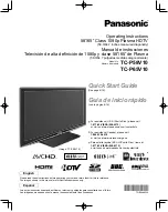
Page 104: ...reen Main Body No upper screen Power ON Replace the upper Y buffer board No lower screen Replace the lower Y buffer board No 1 7 vertical screen Replace the corresponding X buffer board No 1 2 vertical screen Replace the panel No 3 4 vertical screen Replace the panel ...

Reviews: