Samsung OFFICESERV 100 Series, Installation Manual
The Samsung OFFICESERV 100 Series System Administration Manual is an essential resource for managing and configuring your Samsung OFFICESERV communication system. With easy-to-follow instructions and comprehensive information, this manual ensures efficient system administration. Download the free manual now from manualshive.com to maximize your Samsung OFFICESERV experience.
Share
Download


Reviews:
No comments
Related manuals for OFFICESERV 100 Series

Univerge SV8100
Brand: NEC Pages: 5

Univerge SV8100
Brand: NEC Pages: 278

Univerge SV8100
Brand: NEC Pages: 986

OFFICESERV 100 Series
Brand: Samsung Pages: 90

OfficeServ 7000 Series
Brand: Samsung Pages: 487
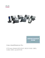
Small Business Pro SPA 502G
Brand: Cisco Pages: 300

Univerge SV8100
Brand: NEC Pages: 2210

TF 510
Brand: switel Pages: 44


