Samsung MCU-Y4NEE, Installation Manual
The Samsung MCU-Y4NEE is an innovative and efficient device designed for optimal performance. To ensure a seamless installation process, we offer a comprehensive Installation Manual that can be easily downloaded for free from our website. Get your hands on this manual at manualshive.com and unlock the full potential of your Samsung MCU-Y4NEE.
Share
Download


Reviews:
No comments
Related manuals for MCU-Y4NEE

nanoe CZ-CNEXU1
Brand: Panasonic Pages: 108

PowerKon QE
Brand: Kampmann Pages: 36

380965
Brand: EUROM Pages: 28

BAYECON103AA
Brand: Trane Pages: 17

SYSVRF JOINT OUT 02 HP
Brand: SystemAir Pages: 2

Gobi II
Brand: Refco Pages: 8

iHarmony 10C16
Brand: Lennox Pages: 16

GLL10
Brand: AERMEC Pages: 48

smart clima GABBIA GA - 700
Brand: Tecnosystemi Pages: 4

UTZ-KXGC
Brand: Fujitsu Pages: 2

RAB24
Brand: GE Pages: 8
RAB26A
Brand: GE Pages: 10
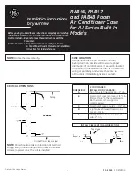
RAB46
Brand: GE Pages: 12

RAB46B
Brand: GE Pages: 10

RAB81
Brand: GE Pages: 8

RAD10
Brand: GE Pages: 2
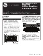
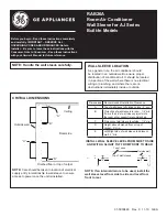
RAG60
Brand: GE Pages: 2
RAK148D1
Brand: GE Pages: 16


