


MICROWAVE OVEN
M735
SERVICE
Manual
MICROWAVE OVEN
CONTENTS
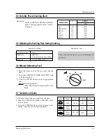
400
560
120
M735
800W
1
2
3
4
5
6
7
8
9
10
20
30
40
60
0
50
250
1. Precaution
2. Specifications
3. Operating Instructions
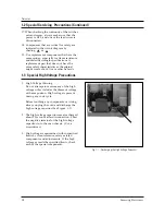
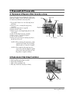
4. Disassembly and Reassembly
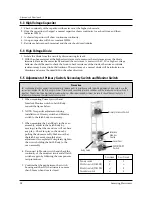
5. Alignment and Adjustments
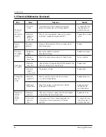
6. Troubleshooting
7. Exploded Views and Parts List
8. Wiring Diagram
NSI