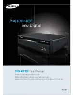
background image

Expansion


into Digital

SNS-400/100


User’s Manua

“

Thanks for purchasing the SNS-400/100.
Before attempting to connect or operate this product,
please read these instructions carefully and save this manual for future use

&OHMJTI

Summary of Contents for iPPLiS SNS-100

Page 1: ...into Digital SNS 400 100 User s Manua Thanks for purchasing the SNS 400 100 Before attempting to connect or operate this product please read these instructions carefully and save this manual for future use OHMJTI ...

Page 2: ......

Page 3: ... the copy reprint and translation to other languages in parts or full of this user manual without the express written consent of SamsungTechwin Co LTD are not allowed aside for general use within the scope of the copyright law A brand that is integrated into Samsung s network products stands for a convenient world Polis made safe Police through Samsung s superior network performance Internet proto...

Page 4: ... 2 Bottom 9 2 2 3 Back 10 2 3 Recommended PC specifications 11 Ch3 Installation and Setting 12 3 1 Power Input 12 3 2 Connecting to Monitor 12 3 3 Connecting to External Control Terminal 13 3 4 Network Configuration and Connection Method 15 3 4 1 Configuration connection using Web page 15 Ch4 How to Use Web Viewer 18 4 1 How to Use Web Viewer 18 4 1 1 Login 18 4 1 2 Web Viewer Screen 18 4 2 Using ...

Page 5: ...4 2 12 Upgrade 30 4 2 13 System Reboot 31 Ch5 Troubleshooting 32 Before Calling for Malfunctions 32 Specifications 34 Note For more information on network manager program please see network manager quick guide and manual file enclosed with CD ...

Page 6: ...mercial environment This equipment generates uses and can radiate radio frequency energy and if not installed and used in accordance with the instruction manual may cause harmful interference to radio communications Operation of this equipment in a residential area is likely to cause harmful interference in which cause the user will be required to correct the interference at his own expense Correc...

Page 7: ...network Warning Symbols Before attempting to connect or operate this product please read these instructions carefully and save this manual for future use Danger Misuse or wrongful operation of the product may result in death injury or bring about other fatal results It indicates absolute caution when operating Caution Misuse or wrongful operation of the product may result in slight injury or damag...

Page 8: ...arefully because they can cause environment pollution y It is dangerous to put the battery in fire heat or short circuit it y Do not use batteries by recharging them Disassembly and Cleaning y There is a risk of malfunction shock or other dangers Please do not disassemble or attempt to fix the product y To prevent malfunction or shock please do not use a wet cloth or oil based cleaning product to ...

Page 9: ...ports 1 composite unit Screen Text Display Functions Using the texts displayed on the monitor screen the camera functions can be adjusted Motion Detection Even without an external motion sensor this product detects motion and sends a signal Therefore by connecting to the alarm device monitoring can be performed much more efficiently Alarm and interoperation Motion Detection function is interoperat...

Page 10: ...00 I O Connection Terminal Users Manual CD Quick Guide Wall Bracket Cross Cable DC 12V Adapter 2 2 Part Names 2 2 1 Front SNS 100 SNS 400 POWER Shows whether server power is connected NETWORK When Network LED flickers it means that the network is operating normally VIDEO Displays whether video input is detected SENSOR Shows SENSOR input USB USB terminal ...

Page 11: ...BRACKET as seen in the below figure y Remove the Foot on the bottom and connect the support to the WALL BRACKET y SNS 100 Bottom Connection Diagram SNS 100 Dimensional Connection Diagram y With Wall Bracket attached Caution The Wall Brackett is provided together with the server When installing support please see the above user s manual ...

Page 12: ...J 45 connectors to connect to Ethernet TERM SWITCH The switch named TERM is for selecting the RS 485 422 connection and turning the termination resistor on and off RS 485 select ON 1 2 RS 422 select OFF 1 2 Apply termination resistor ON 3 4 RS 485 422 Installs serial cable connected to camera that controls pan tilt zoom functions RS 232C Connection terminal to RS 232 C communication device ALARM A...

Page 13: ...ack of the product 2 3 Recommended PC specifications Items Specifications CPU Pentium IV 3 0GHz or higher processor Main Memory 1GB or higher RAM HDD More than 120GB when recording VGA 128M or higher recommended OS Window 2000 XP 2003 Vista Web Browser Internet explorer 5 5 or higher Resolution 1024 768 or higher Network 10 100 Base T Ethernet DirectX 9 0C or higher ...

Page 14: ...ltage V m 0 028 0 018 0 011 0 06 y As seen in Chart 3 1 a voltage drop occurs and thus in the case that the adapter output wire s length is excessively connected to the network a problem can occur with the network server Server Operation Voltage DC 12V 10 Depending on the type and manufacturer of the voltage load wire described in the above chart there may be a deviation 3 2 Connecting to Monitor ...

Page 15: ... 422 RS 232C SENSOR IN RELAY OUT MONITOR VIDEO IN AUDIO IN AUDIO OUT DC 12V TERM ETHERMET T RS 485 422 according to TERM SWITCH connection TERM ON OFF 1 2 RS 485 RS 422 3 4 Termination Resistor ON Termination Resistor OFF RS 485 RS 422 Connection RS 485 I 422 RS 232C SENSOR IN RELAY OUT MONITOR VIDEO IN AUDIO IN AUDIO OUT DC 12V TERM ETHERMET T RS 485 RS 485 I 422 RS 232C SENSOR IN RELAY OUT MONIT...

Page 16: ... AUDIO IN AUDIO OUT DC 12V TERM ETHERMET Input S1 Input S2 Input S3 Input S4 Input S1 S3 Input S1 S2 S3 S4 y In case of selecting Normal Open at setup menu In case of contact type it is short and in case of active type sensor input acts at LOW level y In case of selecting Normal Close at setup menu In case of contact type it is open and in case of active type sensor input acts at high impedance st...

Page 17: ...tion and Connection Method 3 4 1 Configuration connection using Web page 1 Please connect user s PC to SNS 100 400 network server using cross cable Note To configure network the internal IP must be registered in the user s PC After pressing internet protocol TCP IP properties press the advanced button to go into advanced configurations Add with 192 168 1 XXX ...

Page 18: ...etwork server SNS 100 default address SNS 400 default address 3 Please login with administrator s authorization and move to Setup Network page Note The initial ID and password is ID admin PW 11111111 4 Please configure according to the network environment where SNS 100 400 network server will be installed and push Save button to save the configuration LAN xDSL DHCP Configuration ...

Page 19: ...rs are operated through LAN and for small scales IP sharers use DHCP functions Port Configuration Item Description Port Setting The connection port and http ftp port configurations can be set here and the DDNS use can be checked Note Use DDNS changes its IP address every time the user attempts to connect to the ISP and when the product is connected to a cable modem or xDSL modem In this case the u...

Page 20: ...then moves to the appropriate Web page Note Default value is ID admin PW 11111111 If you click Guest button it moves to WebViewer page under the Guest authenticated status However administrator has to permit guest access for this Note If you logged in first in administrator mode please change the password of administrator It can prevent other users from connecting to the administration page 4 1 2 ...

Page 21: ...channel servers CH1 CH4 Compression Video compression mode the mode of compressing video MPEG JPEG Resolution Video resolution the size of video screen transmitted NTSC D1 704x480 Half D1 704x240 CIF 352x240 PAL D1 704X576 Half D1 704X288 CIF 352X288 Frame Rate The number of maximum video frames transmitted per second Designated by user between 1 30 Quality Video quality setting Very High High Mid...

Page 22: ...control button is displayed Camera OSD is displayed Instruction for Camera OSD control button button Moves selection displaying arrows up and down on camera OSD menu button Changes configuration of selected field on camera OSD menu Set button Used when moving to a selected field s lower menu or when setting a selected item Exit button Used when going to the upper menu of a selected field or when t...

Page 23: ...de bar can control focus left slide bar zoom right slide bar The displayed in the middle can be pressed using the mouse as the base point of the Pan Tilt and it will Pan Tilt according to that point 4 2 Using Administration Page 4 2 1 Initialization Screen after Connecting When connection is successful the below screen will be displayed ...

Page 24: ...lity of video screen In case of low speed internet lower the video quality to see seamless video Video Frame Rate Configures the number of transmitted frame per second in the camera Video Channel Selects the video channel to be used in the camera Audio In Channel Selects whether to use the audio input channel in the camera or not Audio Out Channel Selects whether to use the audio output in the cam...

Page 25: ...es the network data of the network server Network Configuration According to the user s network environment it is classified as LAN xDSL or DHCP Item Description LAN In case the network server is connected to the local network or xDSL with a static IP address configure network information to be assigned to the network server xDSL In case of xDSL with a dynamic IP address enter password in User Nam...

Page 26: ...ete and set up user s authority applied only to 4 channel servers Setup User Authority User s authorities set up at Current User are as follows Item Description Video Use video related setup function Compression Resolution Framerate Quality Controls Pan Tilt Zoom Audio output Alarm output Audio In Audio Input Use Whether relevant account is used If not checked log in not permitted Example 1 In cas...

Page 27: ...her to display PTZ control tool on screen OSD Display Set whether to display OSD menu in camera Preset Register use selected preset or delete registered preset Swing Set whether to activate in set swing mode Group Set whether to activate registered group mode Device ID Select ID allotted to camera and differentiate camera to be controlled Mode Select the connected camera s protocol per manufacture...

Page 28: ... time at one preset point Group Setup Item Description Group No Sets the desired group number Preset No Sets each point s preset number Travel Speed Sets the travel speed between each point interval Dwell Time Sets the stop time at each position 4 2 7 Motion Detection This sets up motion detection function of the network server Motion Detection Configuration Item Description Channel Set Used when ...

Page 29: ...on Set up time to operate relay It defines the period from the time when sensor detects event to the time when relay is released FTP In case event occurs by sensor or Motion Detection MD on the screen decide whether transferring related information to FTP E mail In case event occurs by connected sensor or Motion Detection MD on the screen decide whether transferring related information by e mail F...

Page 30: ...ed by e mail or to FTP are varied according to the set up of Video Compression at Admin page Basic MPEG Video length is set by Duration of Digital Out Relay Alarm Setup File extension is ste you can play this by SLiM Player JPEG JPG type image file attached 4 2 9 Record Record Page Item Description USB Memory Size Displays the entire capacity of the USB memory USB Memory Recordable Size Displays t...

Page 31: ...unction specs Interoperation with events MD V Loss Sensor Saves pre and post 5 seconds of the corresponding channel MPEG saves as set frame JPEG 1 page 1 second When audio is on the audio is also saved REPEAT RECORDING When all storage space is used it deletes old save data and begins a new save cycle Up to 1 000 events can be saved It saves it in the same resolution as that of the LIVE screen D1 ...

Page 32: ...irmware Upgrade firmware of SNS 100 400 network server Note Upgrade methods are as shown below Check current version Press search and select the latest version firmware file and press the send button When send is pressed upgrades are done and it automatically reboots Lastly check if it is changed to the latest version Caution Upgrades should be performed only by technicians Always perform upgrades...

Page 33: ...f you click Reset button server is returned to initial value when shipped from the factory after confirmation procedure by administrator 4 2 13 System Reboot Server is rebooted after confirmation procedure of administrator Click OK button to reboot server ...

Page 34: ...function is not working Please check if MOTION DETECTION mode is turned on Please check if the MD LEVEL is too low Please check the setting of the MD AREA The screen flickers too much Check if the connected camera faces directly into the sun or lights Check if the cables are properly connected Audio is not working Please check the audio is selected from admin page Please check speaker volume from ...

Page 35: ...heck the camera speed dome protocol See if the proper model and manufacturer is selected at the mode Inspect the cables connected to the device When the contents stored on the USB memory does not appear Make sure not to remove it when it is being saved on the USB Check if the USB is properly connected Make sure that capacity display is accurate on the Record Page When product data is not displayed...

Page 36: ... 20 Users PC Viewer Network Manager DVR Server IPCam Integrated Manager S W Web Page Web ActiveX Control Embedded Web Server S W SDK Supports 3rd party SDK Audio Input Mini Jack X4 Mono Line or Mic level Mini Jack X1 Mono Line or Mic level Audio Output Mini Jack X1 Mono Ethernet RJ 45 Connector X1 10 100 Base Ethernet Sensor Input Terminal X4 Terminal X2 Relay Output Terminal X4 Terminal X2 Serial...

Page 37: ......

Page 38: ...P No Z6806082501B November A 14 ...

Reviews: