background image

DVD RECEIVER AMP

Basic Model : 

HT-X250

SERVICE

Manual

DVD RECEIVER AMP SYSTEM
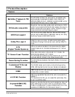
Features

* Multi-Disc Playback & FM Tuner

* DVD-Audio compatible

* USB Host support

* Dolby Pro Logic II

* DTS (Digital Theater Systems)

TV Screen Saver Function

Power Saving Function

Customized TV Screen Display

HDMI

AV SYNC Function

* (HDMI-CEC) Function

- Confidential -

MODEL : HT-X250

* Application : 

HT-X200/X250

Summary of Contents for HT-X250

Page 1: ...ulti Disc Playback FM Tuner DVD Audio compatible USB Host support Dolby Pro Logic II DTS Digital Theater Systems TV Screen Saver Function Power Saving Function Customized TV Screen Display HDMI AV SYNC Function Anynet HDMI CEC Function Confidential MODEL HT X250 Application HT X200 X250 ...

Page 2: ... Samsung Electronics Co Ltd JAN 2007 Printed in Korea Code no AH68 000000 ELECTRONICS ...

Page 3: ... 5 Ch6 TroubleShooting Main 6 1 Output 6 2 In case of Power Protection 6 3 AMP Pre Inspection relating to Power Protection 6 4 Ch7 Exploded Views and Parts List HT X250 Exploded View 7 1 HT X250 Parts List 7 2 Ch9 Block Diagram Block 9 1 Ch10 Wiring Diagram Wiring Diagram 10 1 GND 10 2 VDD 10 3 SMPS 10 4 Ch11 PCB Diagram MAIN PCB 11 1 MAIN PCB Description 11 2 SMPS PCB 11 4 Ch12 Schematic Diagram ...

Page 4: ...rrent for Appliances and Underwriters Laboratories UL Publication UL1410 59 7 With the unit completely reassembled plug the AC line cord directly into a 120V AC outlet With the unit s AC switch first in the ON position and then OFF measure the current between a known earth ground metal water pipe etc and all exposed metal parts Examples Handle brackets metal cabinets screwheads and control shafts ...

Page 5: ...nplug the unit s AC power cord from the AC power source before attempting to a Remove or reinstall any component or assembly b Disconnect an electrical plug or connector c Connect a test component in parallel with an electrolytic capacitor 3 Some components are raised above the printed circuit board for safety An insulation tube or tape is sometimes used The internal wiring may be clamped to preve...

Page 6: ...ready to install it Most replacement ESDs are packaged with leads that are electrically shorted together by conductive foam aluminum foil or other conductive materials 8 Immediately before removing the protective material from the leads of a replacement ESD touch the protective material to the chassis or circuit assembly into which the device will be installed 9 Minimize body motions when handing ...

Page 7: ...d plane which is grounded 3 The repair technician must wear a wrist strap which is grounded to the copper sheet 4 To remove the Optical Pickup block Place the set on the conductive sheet and momentarily touch the conductive sheet with both hands While working do not allow any electrostatic sources such as clothes to touch the unit 5 Ground the Short Terminal located on the PCB inside the Pickup As...

Page 8: ...ed by Digital Theater Systems Inc It delivers full frequency 5 1 channel sound DTS Digital Theater Systems If the main unit remains in stop mode for 3 minutes the Samsung logo appears on TV screen The HT X250 automatically switches itself into the power sav ing mode after 20 minutes in the Screen Saver mode TV Screen Saver Function The HT X250 automatically shuts itself off after 20 minutes in Sto...

Page 9: ...12 4 in x 7 5 in 41 F 95 F 10 75 10dB 60dB 0 5 1 0Vp p 75Ω load Y 1 0Vp p 75Ω load Pr 0 70Vp p 75Ω load Pb 0 70Vp p 75Ω load Impedance 85 115 100W x 2 3Ω 100W 3Ω 100W x 2 3Ω 100W 3Ω 20Hz 20KHz 70dB 60dB AUX 400mV Speaker system Impedance Frequency range Output sound pressure level Rated input Maximum input Dimensions W x H x D Weights SPEAKER Subwoofer speaker 3Ω DCR 3 4Ω 40Hz 200Hz 86dB W M 100W ...

Page 10: ...Samsung Electronics 2 3 3 Accessories Commodity Name Commodity Photo Materials Code AH59 01778P Remote Control AH42 00017A FM Antenna AH39 40001V Video Cable AH68 01943R User s Manual ...

Page 11: ...2 4 Samsung Electronics 4 Specification Comparison X250 Model Name Q100 2006 2007 Year 500W 600W O O 5 1 CH O O USB HOST OUTPUT O O HDMI OUT X O HDMI CEC ...

Page 12: ...ntrol button 1 2 3 4 5 6 7 8 9 10 1 5 1 Channel Speaker Output Connectors 2 Component Video Output Jacks Connect a TV with component video inputs to these jacks 3 Video Output Jack Connect the TV s Video Input jack VIDEO IN to the VIDEO OUT Jack 4 External Digital Optical Input Jack Use this to connect external equipment capable of digital output 5 HDMI OUT Jack 6 TX Card Connection WIRELESS 7 AUX...

Page 13: ...with or near the speakers They could get hurt if a speaker falls When connecting the speaker wires to the speakers make sure that the polarity is correct Keep the subwoofer speaker out of reach of children so as to prevent children from inserting their hands or alien substances into the duct hole of the subwoofer speaker Do not hang the subwoofer on the wall through the duct hole 1 2 Connecting th...

Page 14: ...le between ZOOM X2 and ZOOM OFF 2 Press the Cursor button to move to the area you want to enlarge Zoom Function A DivX file can be zoomed only in ZOOM X2 mode DivX files have Avi file extensions however not all Avi files are DivX and may not be playable in this unit DivX Press the AUDIO button If there are multiple audio tracks on a disc you can toggle between them Each time you press the button y...

Page 15: ... STOP button Safe USB Removal To prevent damage to the memory stored in the USB device perform safe removal before disconnecting the USB cable 1 Press the STOP button twice in a row The display will show REMOVE USB 2 Remove the USB cable PHONES USB During playback press the button When there is more than one file and you press the button the next file is selected When there is more than one file a...

Page 16: ...e firmware 1 Prepare DISC CD DVD or the USB device that contains HEX file for Update 2 Play the DISC or connect the USB cable then Updating will appear on the screen then Power will go on and out 3 Then DISC TRAY will OPEN then remove DISC or take off USB cable making Unit NO DISC state 4 Press STOP button of Main Unit 5 seconds more Display Indicator shows INITIALIZE then Power go out 5 Initializ...

Page 17: ...Samsung Electronics 5 1 5 How to disassemble 1 Separate CABINET TOP A Lay down MAIN SET B Rotate STAND 20 degree to separate from MAIN SET ...

Page 18: ...5 2 Samsung Electronics 2 Separate REAR COVER A Unfasten 11 screw B Lift up COVER to the direction of arrow And separate power cord ...

Page 19: ...Samsung Electronics 5 3 3 Separate CHASSIS BACK A Separate 2 connector wire B Separate PCB wire C Unfasten 4 SCREW arrow remark ...

Page 20: ...5 4 Samsung Electronics D Separate MAIN SET ...

Page 21: ...A Unfasten 2 SCREW to separate COVER CHASSIS A Unfasten 2 SCREW to separate COVER CHASSIS Samsung Electronics 5 5 4 Separate PCB ...

Page 22: ...6 1 Samsung Electronics 6 TroubleShooting 1 Main ...

Page 23: ...Samsung Electronics 6 2 2 Output ...

Page 24: ...6 3 Samsung Electronics 3 1 In case of Power Protection ...

Page 25: ...Samsung Electronics 6 4 3 2 SMPS Ass y Power check ...

Page 26: ...6 5 Samsung Electronics 3 3 AMP Pre Inspection relating to Power Protection ...

Page 27: ...Samsung Electronics 6 6 4 FAN Error Check ...

Page 28: ...6 7 Samsung Electronics 5 FAN CHECK Error ...

Page 29: ...Samsung Electronics 6 8 6 1 Communication Failure ...

Page 30: ...6 9 Samsung Electronics 6 2 Voltage Failure ...

Page 31: ...Samsung Electronics 6 10 ...

Page 32: ...6 11 Samsung Electronics 6 3 Communication Failure ...

Page 33: ...Samsung Electronics 6 12 7 Checking out AMP PCB ...

Page 34: ...6 13 Samsung Electronics 8 AMP PCB Short Check flow ...

Page 35: ...Views and Parts List 1 HT X250 Exploded View AC010 PCB DISPLAY AC155 PCB MAIN PCB PHONE_USB AS382 AS381 SLOT MECHA PCB FUNCTION AK170 PCB POWER AA172 AC040 AL150 AC137 AC169 AA006 AA007 AM020 PCB SMPS HOLDER SMPS TUNER AA089 AB385 AF025 ...

Page 36: ... SUPPORT MECHA L AH61 02354A 1 AS382 SUPPORT MECHA R AH61 02355A 1 AA172 ASSY KNOB POWER AH97 02177A 1 PCB DISPLAY PCB DISPLAY AH41 01019A 1 PCB MAIN PCB MAIN 1 PCB PHONE_USB PCB PHONE_USB 1 PCB POWER PCB POWER AH41 01020A 1 PCB FUNCTION PCB FUNCTION 1 PCB SMPS PCB SMPS AH44 00151A 1 TUNER TUNER AH40 00108A 1 HOLDER SMPS HOLDER SMPS AH61 02353A 1 SLOT MECHA SLOT MECHA AH59 01773A 1 ...

Page 37: ... CHIP 1000nF 80 20 25V Y5V 2012 AC89 2203 005249 C CER CHIP 100nF 10 50V X7R 1608 AC91 2203 005249 C CER CHIP 100nF 10 50V X7R 1608 AC93 2203 005249 C CER CHIP 100nF 10 50V X7R 1608 AC95 2203 005249 C CER CHIP 100nF 10 50V X7R 1608 AC96 2203 002793 C CER CHIP 1000nF 80 20 25V Y5V 2012 AC97 2203 002793 C CER CHIP 1000nF 80 20 25V Y5V 2012 AC99 2203 005249 C CER CHIP 100nF 10 50V X7R 1608 AD2 0401 0...

Page 38: ...1 8W TP 2012 AR176 2007 000686 R CHIP 3 3Kohm 5 1 8W TP 2012 AR23 2007 000941 R CHIP 47Kohm 5 1 8W TP 2012 AR42 2007 000253 R CHIP 1 5ohm 5 1 4W TP 3216 AR65 2007 000070 R CHIP 0ohm 5 1 10W TP 1608 AR66 2007 000090 R CHIP 10Kohm 5 1 10W TP 1608 AR67 2007 000097 R CHIP 47Kohm 5 1 10W TP 1608 AR68 2007 000070 R CHIP 0ohm 5 1 10W TP 1608 AR69 2007 000070 R CHIP 0ohm 5 1 10W TP 1608 AR70 2007 000455 R...

Page 39: ...m 468nm FD118 0601 002151 LED SMD BLUE 1 6x0 8x0 35mm 468nm FD119 0601 002151 LED SMD BLUE 1 6x0 8x0 35mm 468nm FD12 0601 002151 LED SMD BLUE 1 6x0 8x0 35mm 468nm FD120 0601 002151 LED SMD BLUE 1 6x0 8x0 35mm 468nm FD121 0601 002151 LED SMD BLUE 1 6x0 8x0 35mm 468nm FD122 0601 002151 LED SMD BLUE 1 6x0 8x0 35mm 468nm FD123 0601 002151 LED SMD BLUE 1 6x0 8x0 35mm 468nm FD124 0601 002151 LED SMD BLU...

Page 40: ... 8x0 35mm 468nm FD75 0601 002151 LED SMD BLUE 1 6x0 8x0 35mm 468nm FD76 0601 002151 LED SMD BLUE 1 6x0 8x0 35mm 468nm FD77 0601 002151 LED SMD BLUE 1 6x0 8x0 35mm 468nm FD78 0601 002151 LED SMD BLUE 1 6x0 8x0 35mm 468nm FD79 0601 002151 LED SMD BLUE 1 6x0 8x0 35mm 468nm FD8 0601 002151 LED SMD BLUE 1 6x0 8x0 35mm 468nm FD80 0601 002151 LED SMD BLUE 1 6x0 8x0 35mm 468nm FD81 0601 002151 LED SMD BLU...

Page 41: ... 000309 R CHIP 10ohm 5 1 10W TP 1608 HR15 2007 000309 R CHIP 10ohm 5 1 10W TP 1608 HR16 2007 000309 R CHIP 10ohm 5 1 10W TP 1608 HR17 2007 000309 R CHIP 10ohm 5 1 10W TP 1608 HR18 2007 000309 R CHIP 10ohm 5 1 10W TP 1608 HR19 2007 000309 R CHIP 10ohm 5 1 10W TP 1608 HR2 2007 000075 R CHIP 220ohm 5 1 10W TP 1608 HR20 2007 000309 R CHIP 10ohm 5 1 10W TP 1608 HR21 2007 000070 R CHIP 0ohm 5 1 10W TP 1...

Page 42: ... 000074 R CHIP 100ohm 5 1 10W TP 1608 MR109 2007 000074 R CHIP 100ohm 5 1 10W TP 1608 MR11 2007 000070 R CHIP 0ohm 5 1 10W TP 1608 MR112 3301 001069 BEAD SMD 120ohm 1 6x0 8x0 8mm 200mA TP MR113 3301 001069 BEAD SMD 120ohm 1 6x0 8x0 8mm 200mA TP MR114 3301 001069 BEAD SMD 120ohm 1 6x0 8x0 8mm 200mA TP MR115 3301 001069 BEAD SMD 120ohm 1 6x0 8x0 8mm 200mA TP MR116 2007 000113 R CHIP 33ohm 5 1 10W TP...

Page 43: ...0189 C CER CHIP 100nF 80 20 25V Y5V 1608 RC63 2203 000189 C CER CHIP 100nF 80 20 25V Y5V 1608 RC64 2401 001092 C AL 330uF 20 10V GP 8x11 5 2 5m RC65 2203 000236 C CER CHIP 0 1nF 5 50V C0G 1608 RC66 2203 005065 C CER CHIP 1000nF 80 20 10V Y5V 1608 RC7 2203 000189 C CER CHIP 100nF 80 20 25V Y5V 1608 RC72 2401 000414 C AL 10uF 20 16V GP TP 4x7 5 RC73 2203 000280 C CER CHIP 0 01nF 0 5pF 50V C0G 1608 R...

Page 44: ...X7R 1608 UC41 2401 000042 C AL 100uF 20 16V GP TP 6 3x7 5 UC42 2203 005249 C CER CHIP 100nF 10 50V X7R 1608 UC43 2401 001364 C AL 470uF 20 16V GP TP 10x12 5 5 UC5 2402 000173 C AL SMD 4 7uF 20 35V GP TP 4 3x4 3x5 UC50 2203 005249 C CER CHIP 100nF 10 50V X7R 1608 UC51 2203 005148 C CER CHIP 100nF 10 16V X7R 1608 UC52 2203 005148 C CER CHIP 100nF 10 16V X7R 1608 UC53 2402 000167 C AL SMD 100uF 20 10...

Page 45: ...03 000280 C CER CHIP 0 01nF 0 5pF 50V C0G 1608 VC15 2203 000280 C CER CHIP 0 01nF 0 5pF 50V C0G 1608 VC16 2203 000280 C CER CHIP 0 01nF 0 5pF 50V C0G 1608 VC17 2203 000280 C CER CHIP 0 01nF 0 5pF 50V C0G 1608 VC2 2402 001049 C AL SMD 10uF 20 16V GP TP 3 3x3 3x5 4 VC3 2203 005819 C CER CHIP 1000nF 80 20 16V Y5V 1608 VC4 2203 005819 C CER CHIP 1000nF 80 20 16V Y5V 1608 VC5 2203 005819 C CER CHIP 100...

Page 46: ...404 000165 SWITCH TACT 12V 50mA 160gf 6x6mm SPST FSW9 3404 000165 SWITCH TACT 12V 50mA 160gf 6x6mm SPST FSW2 3404 000165 SWITCH TACT 12V 50mA 160gf 6x6mm SPST FSW1 3404 000165 SWITCH TACT 12V 50mA 160gf 6x6mm SPST FSW10 3404 000165 SWITCH TACT 12V 50mA 160gf 6x6mm SPST FSW11 3404 000165 SWITCH TACT 12V 50mA 160gf 6x6mm SPST FSW12 3404 000165 SWITCH TACT 12V 50mA 160gf 6x6mm SPST Location no Code n...

Page 47: ...9 1 Samsung Electronics 9 Block Diagram 1 Block ...

Page 48: ...Samsung Electronics 10 1 10 Wiring Diagram 1 Wire Sheet ...

Page 49: ...10 2 Samsung Electronics 2 GND ...

Page 50: ...Samsung Electronics 10 3 3 VDD ...

Page 51: ...10 4 Samsung Electronics 4 SMPS ...

Page 52: ...11 1 Samsung Electronics 11 PCB Diagram 1 MAIN PCB ...

Page 53: ...Samsung Electronics 11 2 2 MAIN PCB Description ...

Page 54: ...11 3 Samsung Electronics 2 MAIN PCB Description ...

Page 55: ...Samsung Electronics 11 4 3 SMPS PCB ...

Page 56: ...Samsung Electronics 12 1 This Document can not be used without Samsung s authorization 12 Schematic Diagram 1 1 MAIN MPEG ...

Page 57: ...12 2 Samsung Electronics This Document can not be used without Samsung s authorization 1 2 MAIN MICOM ...

Page 58: ...Samsung Electronics 12 3 This Document can not be used without Samsung s authorization 1 3 MAIN HDMI ...

Page 59: ...12 4 Samsung Electronics This Document can not be used without Samsung s authorization 1 4 MAIN DSP ...

Page 60: ...Samsung Electronics 12 5 This Document can not be used without Samsung s authorization 1 5 MAIN AMP ...

Page 61: ...12 6 Samsung Electronics This Document can not be used without Samsung s authorization 1 6 MAIN JACK 1 ...

Page 62: ...Samsung Electronics 12 7 This Document can not be used without Samsung s authorization 1 7 MAIN JACK 2 ...

Page 63: ...12 8 Samsung Electronics This Document can not be used without Samsung s authorization 1 8 MAIN LED ...

Page 64: ...Samsung Electronics 12 9 This Document can not be used without Samsung s authorization 2 KEY ...

Page 65: ...10 RA1 TS6B05G BDL1 CA8 471 M 47K RM7 1N4148 DA5 ZDA1 1N5235B 2 7K RM9 50V 47uF CM6 630V 103 CM1 PCM3B PC817 R86 1 3K F 1000uF 50V 105 C86 1000uF 50V 105 C87 RL1 1 5M 1 2W PC817 PCM2A 1KV 103 CA11 THL1 3D15 DA6 UF4004 RA9 100 50V 47uF 105 CA10 33 RA4 UF4007 DA2 33K 2W RA2 QM1 A1266 50V 47uF CM4 ZDM3 1N5239B 2W200K RM5 FR104 DM3 330uF 450V CL4 UF4007 DM2 C81 101 1KV R83 4 7K R87 200 F 47 F R88 ZD91...

Page 66: ...13 1 Samsung Electronics 13 Circuit Board Description 1 PCB Assy Layout 1 HT X250 X200 ...

Page 67: ...Samsung Electronics 13 2 2 Functional Description SMPS Main Front ...

Page 68: ...13 3 Samsung Electronics 3 Functional Description Amp HDMI Video ...

Page 69: ...Samsung Electronics 13 4 4 1 MAIN PCB Block 4 2 MAIN PCB Connectors ...

Page 70: ...13 5 Samsung Electronics 5 MAIN PCB HDMI VIDEO OUT ...

Page 71: ...Samsung Electronics 13 6 6 1 SUB PCB Block 6 2 SUB PCB Connectors ...

Page 72: ...13 7 Samsung Electronics 7 AMP PCB Block ...

Page 73: ...Samsung Electronics 13 8 8 New Functions ...

Page 74: ...13 9 Samsung Electronics 8 New Functions ...

Reviews: