Technical Support Guide
Epica DGX 16/32 and Enova DGX Cable Management
1
Technical Support Guide
Epica DGX 16/32 and Enova DGX Cable Management
Applicability
This
Technical Support Guide
provides instructions for installing (and removing) cable management bars for
SC Optical Boards
on
Epica DGX 16/32 Distribution Matrices and for
DXLink Fiber Boards
on all Enova DGX Digital Media Switchers (DGX 8/16/32/64
and DGX 100 Series).
Attaching Cable Management Bars
Items included in Sales # FG1056-700 (Cable Bar Kit only) and in Cable Bar Kit # KA1056-700 (which ships with SC Optical and
DXLink Fiber Boards):
1 cable management bar
4 screws (3 required)
When cable management bars are used, they need to be installed before the cables are attached.
CAUTION:
Do
not
severely bend or kink the fiber optic cable. Irreversible damage can occur. Refer to the physical limitations (bend
radius) specified for the cable by the manufacturer.
To install a cable management bar:
1.
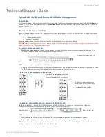
32x32 size enclosures only
– Loosen the two captive screws that hold the connector numbering plate at the top of the
connectors. Remove the connector numbering plate and set aside.
Connector numbering plate
FIG. 1
Connector numbering plate (Epica DGX 32 shown)
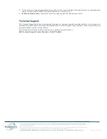
2.
Align the two screw holes on the end of the cable management bar with the two screw holes on the end of the board as shown
in FIG. 2. (Note the position of the long part of the bar in relation to the screw holes.)
Epica DGX 32, Enova DGX 32, Enova DGX 3200
Fasten cable management bar with
two screws on one end and one on
the other end (do
not
over tighten)
Tie cable to cable management
bar far enough from connector to
allow for manufacturer’s
recommended bend radius
Epica DGX 16, Enova DGX 8/16/64, Enova DGX 800/1600/6400
NOTE:
On Epica DGX 16, Enova DGX 8/16/64, and Enova DGX 800/1600/6400 enclosures, the orientation of the cable
management bars is reversed from boards in the left slots to boards in the right slots
.
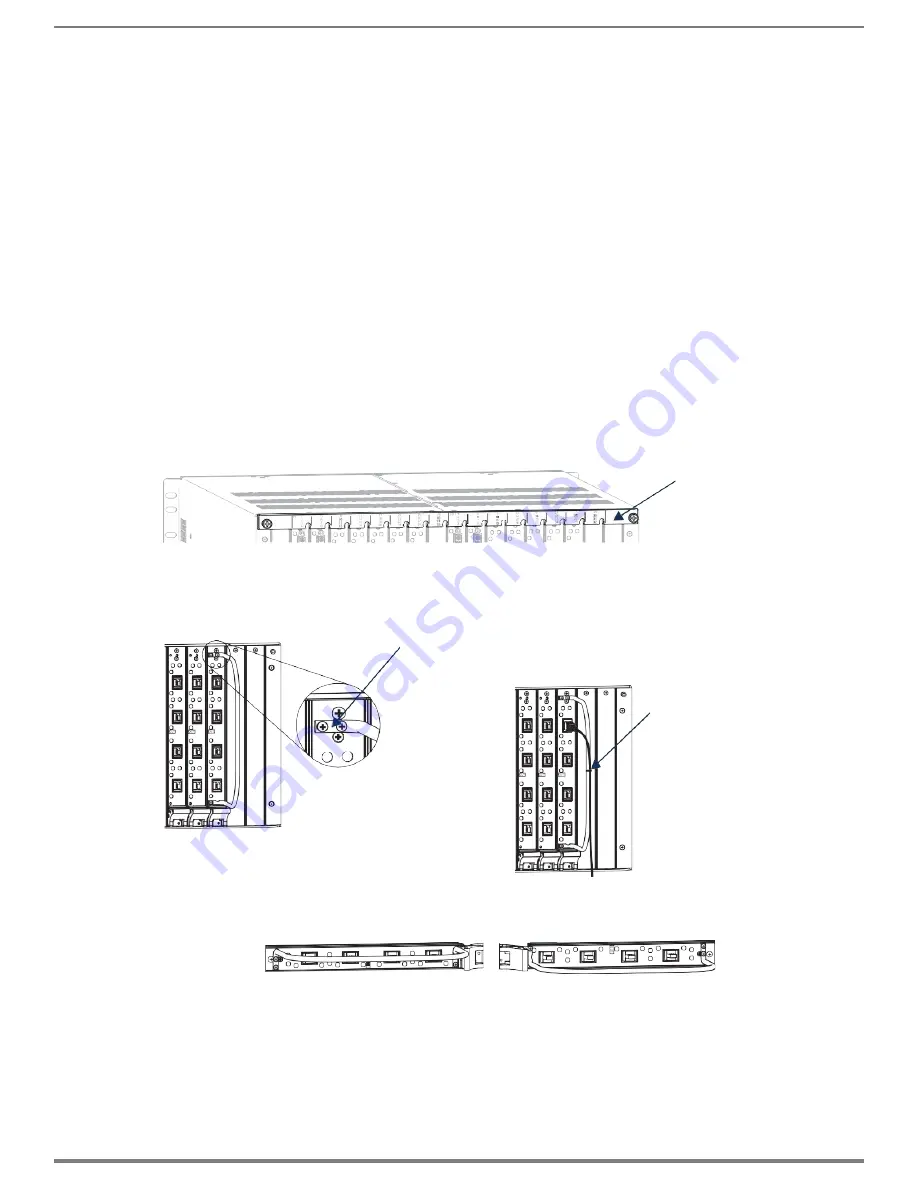
Board in left slot
Board in right slot
FIG. 2
Installation of cable management bars
3.
Insert and tighten the two screws at the end of the cable management bar (do
not
over tighten the screws).
4.
Align, insert, and tighten the single screw at the other end of the cable management bar (do
not
over tighten).
TIP:
When using cable management bars with fiber boards, we recommend the use of soft ties (e.g., Velcro type hook-and-loop
strips) instead of nylon cable ties, which can break fiber cables.


