

QUICK START GUIDE
VARIA-80
8” Touch Panel
Overview
AMX VARIA-80 (AMX-UTP0811) is an 8” professional-grade touch panel designed
to adapt to the unique needs of your environment by offering a selection of
personas. Varia personas are pre-loaded apps that define the entire panel
experience.
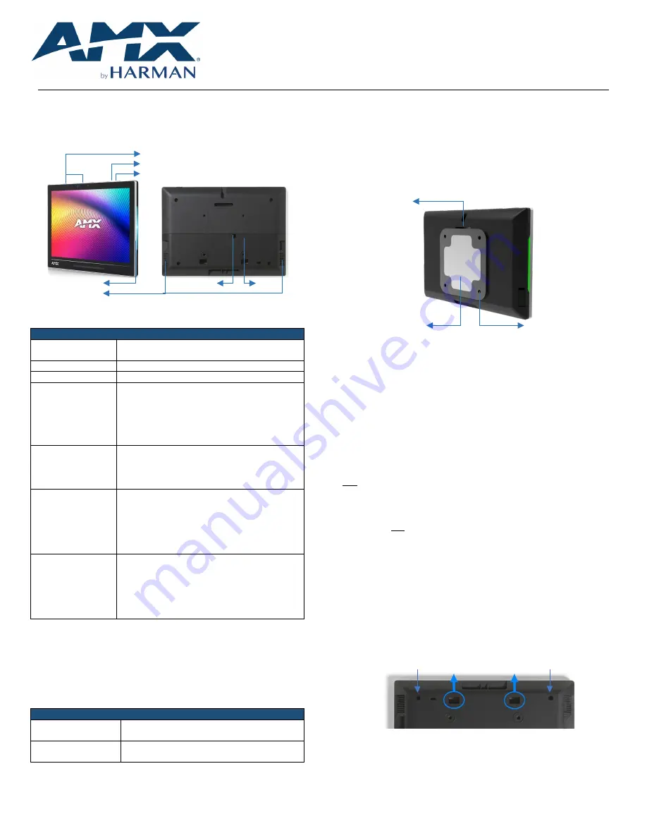
Microphones
Settings Button
Function Button
Side LED
LAN/POE
USB
Speakers
FIG. 1
AMX VARIA-80 Touch Panel
Product Specifications
VARIA-80 SPECIFICATIONS
Dimensions (HWD)
5 7⁄8” x 7 15⁄16” x 7⁄8”
(148.9 mm x 201.2 mm x 21.7 mm)
Product Weight
1.17 lb (532 g)
Power Consumption
PoE, 802.3af, 15.4 watt
External Power
Supply Required
Optimal performance requires use of one of the
following AMX PoE power supplies (not included):
•
PS-POE-AF-TC, PoE Injector, 802.3AF
Compliant (FG423-83)
•
PS-POE-AT-TC, PoE Injector, 802.3AT
Compliant (FG423-84)
Certifications &
Compliance
•
UL
•
CE
•
CB
•
FCC Class B (-5dB)
Environmental
Operating Temperature
•
0°C - 40° C (32°F – 104°F)
•
5% - 85% Humidity
Storage Temperature
•
-20°C –
6
0° C (4°F – 140°F)
•
5% - 90% Humidity
Included Accessories
•
Mounting Plate
•
Adhesive Pad
•
Adhesive decal for backside of glass
•
Set Screw
•
Rear Cover Screws
•
Installation Template
VARIA-80 Installation
Varia can be surface-mounted onto a wall, glass or other smooth surface, or
connect to any number of popular VESA mounts with the included mounting
bracket & hardware.
The VARIA-80 converts to a tabletop touch panel when used in conjunction with
a tabletop stand accessory (sold separately).
TABLETOP STAND ACCESSORIES
VARIA-ACS-80F
(AMX-UMT-0801)
AMX Varia Fixed Tabletop Stand
for VARIA-80
VARIA-ACS-810A
(AMX-UMT-8111)
AMX Varia Angle-Select Tabletop Stand
for VARIA-80, VARIA-100, & VARIA-100N
Power Over Ethernet
Power is supplied via Power Over Ethernet (PoE), utilizing an AMX certified PoE
injector such as the PS-POE-AF-TC (FG423-83) or compatible network switch
which is classified as ES1 and PS2 output in accordance with IEC/EN/UL 62368
-1.
Connect the Ethernet cable to the RJ-45 port on the VARIA-80.
Mounting Plate
The included mounting plate contains a 75x75 VESA hole pattern, set screw, and
dedicated area for the included adhesive pad.
Set Screw
Adhesive Pad
75x75 VESA
FIG. 2
Mounting Plate
STEP 1: Installation Prerequisites
Prior to touch panel installation, identify a proper installation surface in
accordance with local laws and building codes. Ensure that your category cable
(networking cable) has access to the location.
STEP 2: Install the Mounting Plate
If installing on wall
, mark your surface using the included installation template
for the four (4) VESA holes and one (1) desired cable pass-thru location. Drill
holes as required and screw the mounting bracket onto the surface, using
appropriate hardware for the surface (ie. drywall, concrete, brick, etc.). Make
sure to orient the mounting bracket with the set screw on TOP and the two
mounting tabs on the BOTTOM.
Note: Screws with large heads (eg. some pan head screws) will protrude out of the mounting
plate recess and interfere with the touch panel. Use screws with flat or low profile heads.
If installing on glass or other smooth surface
using the adhesive pad, first clean
& dry all surfaces completely. Apply the adhesive pad to the mounting bracket,
only exposing one adhesive side of the pad. Then adhere the mounting bracket
to the surface with the set screw hole facing UP and the two tabs on the
BOTTOM. Make sure it is a secure fit, but do not apply too much pressure as glass
may break.
The included backside decal can be used to hide the adhesive & mounting plate
from view, on the other side of the glass. Carefully align the decal, then adhere
the decal to the other side of the glass (opposite the mounting bracket).
STEP 3: Route Category Cable
Remove the touch panel’s lower rear cover by removing two (2) screws (if
installed). Place your thumbs on the rectangular access holes, and push the
lower cover away from you.
FIG. 3
Lower Cover Holes
Plug in the networking cable and route it out one (1) of the three (3) available
openings in the lower cover: left, right, or bottom. Once fully seated, reattach
the lower rear cover.
Screw Location
Screw Location


