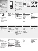


GSM TELEPHONE
GT-S5200
1.
Safety Precautions
2.
Specification
3.
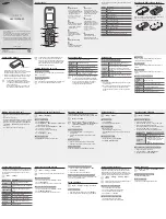
Product Function
4.
Array course control
5.
Exploded View and Parts list
6.
MAIN Electrical Parts List
7.
Disassembly and Assembly
Instructions
8.
Block Diagrams
9.
PCB Diagrams
10. Chart of Troubleshooting
11. Reference data
GSM TELEPHONE
CONTENTS
Summary of Contents for GT-S5200
Page 89: ...www s manuals com ...