background image

ERV

(Energy Recovery Ventilator)

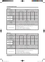
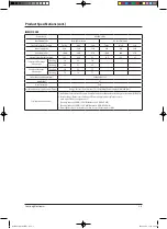
Basic : RHF-025EB/050EB
Model : RHF025EE

RHF035EE
RHF050EE
RHF080EE
RHF100EE

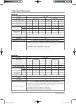
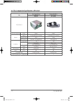
Model Code : RHF025EE

RHF035EE
RHF050EE
RHF080EE
RHF100EE

ERV(Energy Recovery Ventilator)

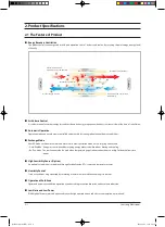
THE FEATURE OF PRODUCT


Heat Exchange Ventilation System 


Energy Recovery Ventilator 


Humidity Control


Operation at Cold Places 


Air Volume Control  


(Be able to control air volume)


Automatic Operation System


Heat-EX/By-Pass Conversion Function  


Indoor Temperature Sensor (Option)
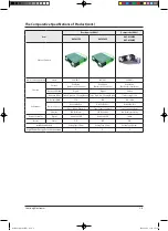
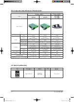
RHF025EE

Refer to the service manual in the GSPN(see the rear cover) for the more information.

RHF035EE, RHF050EE

RHF080EE, RHF100EE

27723A(1)_RHF-025EB_co.indd   1

2007-05-09   ソタネト 3:05:58

Summary of Contents for ERV RHF025EE

Page 1: ...ExchangeVentilation System Energy RecoveryVentilator Humidity Control Operation at Cold Places AirVolume Control Be able to control air volume Automatic Operation System Heat EX By Pass Conversion Function IndoorTemperature Sensor Option RHF025EE Refer to the service manual in the GSPN see the rear cover for the more information RHF035EE RHF050EE RHF080EE RHF100EE 27723A 1 _RHF 025EB_co indd 1 200...

Page 2: ... 5 2 4 Option Specifications 2 7 13 Alignment and Adjustments 3 1 3 1 Error Mode and Check Method 3 1 3 2 Option Switch Key Function Address 3 3 14 Disassembly and Reassembly 4 1 4 1 RHF025EE 4 2 4 2 RHF035EE RHF050EE RHF080EE RHF100EE 4 16 15 Exploded Views and Parts List 5 1 5 1 RHF025EE 5 1 5 2 RHF035EE RHF050EE RHF080EE RHF100EE 5 7 16 Electrical Parts List 6 1 6 1 MAIN PCB 6 1 17 Wiring Diagr...

Page 3: ...tems to be checked first 12 1 12 2 When Ventilator stops operation 12 1 12 3 Errors and Solutions 12 2 12 4 Fault Diagnosis by Symptom 12 3 13 Block Diagram 13 1 14 Reference Sheet 14 1 14 1 Ventilator Operation Priniple 14 1 14 2 Index for Model Name 14 2 14 3 Cleaning the Dust Filter 14 3 14 4 Cleaning the Heat Exchange Element 14 5 14 5 Q A for Non trouble 14 7 14 6 Terminology 14 8 27723A 1 _R...

Page 4: ...that these installations are carried out by qualified personnel to avoid electric shock or fire Perform the installation securely referring to the installation manual Incomplete installation could cause personal injury due to fire electric shock or the unit falling Do not install the product in a place where it is or might be exposed to inflammable gas leakage When the unit is exposed to inflammab...

Page 5: ...om the product away from a burner It may cause incomplete combustion Do not utilize the ventilator to preserve machinery foods animals plants or cosmetic products It may cause damage to the machinery foods animals plants or cosmetic products Do not spray insecticide or other inflammable materials on the product It may cause unit falling or fire Make sure to keep the product away from water The pro...

Page 6: ...tric shock or injury Do not utilize steel scrubber or chemicals such as benzene or thinner It may cause discoloration or unit falling Do not expose animals or plants to the winds from the unit for a long period of time It may damage animals or plants Do not put hands or sticks into the air suction duct or air outlet of the product It may cause injury as ventilator fan is rotating fast Do not attem...

Page 7: ...indoor heating and cooling By Pass Mode The ventilation method is used when temperature gap of indoor and outdoor is not big Outdoor air flows into indoor High Sensibility Sensor Option An optimal air condition is maintained through Carbon Dioxide CO2 sensor and temperature sensor Humidity Control Fresh air conditions are guaranteed by recovering moisture in winter while exhausting it in summer Op...

Page 8: ...4 C WB 3 Duct length refers to its size when friction loss coefficient stands at 0 02 RHF025EE Power Source AC220V 60Hz Ventilation Mode Heat Ex Ventilation By Pass Ventilation The Level of the Air Volume Turbo High Low Turbo High Low Power Supply W 115 100 85 115 100 85 Air Volume m h 350 300 260 350 300 260 External Static Pressure mmAq 17 0 12 1 9 0 17 0 12 1 9 0 Temperature Exchange Efficiency...

Page 9: ...0 44 C WB 3 Duct length refers to its size when friction loss coefficient stands at 0 02 RHF050EE Power Source AC220V 60Hz Ventilation Mode Heat Ex Ventilation By Pass Ventilation The Level of the Air Volume Turbo High Low Turbo High Low Power Supply W 340 290 240 340 290 240 Air Volume m h 800 700 600 800 700 600 External Static Pressure mmAq 17 7 12 4 8 1 17 7 12 4 8 1 Temperature Exchange Effic...

Page 10: ...widthxheightxdepth mm 1 220 340 1 135 Weight kg 67 Duct Size mm 250 Air Volume Control Specifications Turbo Range External Static Pressure 7 5 18 5 mmAq Power Supply 270 0 460 0 W Trial Operation Conditions 1 Air Volume External Static Pressure Comply with KS Heat Exhaust Ventilation System Standards KS B6879 2 Heat Exchange Temperature Exchange Efficiency Comply with regulations to pro mote high ...

Page 11: ...ethod Digital Analog Operation Mode Turbo High Low Sleeping Option Turbo or High Low Performance Air Volume CMH 250 250 Ventilation Method Heat Ex By Pass Heat Ex By Pass Type 1 Supply Exhaust Type 1 Supply Exhaust Element 1EA Cellulous 1EA Cellulous Plastic Remote Controller Digital Wired and LCD Switch Exterior Chasiss P D P D Installation Method Ceiling Type Fill up Ceiling Type Fill up High Ef...

Page 12: ... Mode Turbo High Low Sleeping Option Turbo High Low Sleeping Option Turbo or High Low Performance Air Volume CMH 350 500 250 1 000 Ventilation Method Heat Ex By Pass Heat Ex By Pass Heat Ex By Pass Type 1 Supply Exhaust Type 1 Supply Exhaust Type 1 Supply Exhaust Element 2EA Cellulous 2EA Cellulous 2EA Cellulous Plastic Remote Controller Digital Wired and LCD Wired and LCD Switch Exterior Chasiss ...

Page 13: ...ption Turbo or High Low Performance Air Volume CMH 800 1 000 800 1 000 Ventilation Method Heat Ex By Pass Heat Ex By Pass Heat Ex By Pass Type 1 Supply Exhaust Type 1 Supply Exhaust Type 1 Supply Exhaust Element 2EA Cellulous 2EA Cellulous 2EA Cellulous Plastic Remote Controller Digital Wired and LCD Wired and LCD Switch Exterior Chasiss P D P D P D Installation Method Ceiling Type Fill up Ceiling...

Page 14: ...STER ventilator After 3 minutes of tracking SLAVE ventilators can not be detected Check option setup SWITCH K8 Check address setup SWITCH Check WIRE disconnection 5 Communication error System failure by communication error after tracking Check address setup SWITCH Check WIRE disconnection 6 Outdoor temperature sensor Short Open Check temperature WIRE disconnection or connection conditions Check PC...

Page 15: ... Check wired remote control communication line terminal Check crossover installation of F1 F2 and F3 F4 11 Communication error by installing COM1 Dual MASTER Check option setup SWITCH K8 12 Damper error When there is no switch input for 100 seconds while monitoring the damper Check DAMPER MOTOR Check DAMPER SWITCH Check PCB connection Check WIRE disconnection 602 609 indicate errors due to ERV wir...

Page 16: ...Samsung Electronics Display Operation KEY Address Set up SW01 SW02 SW05 SW06 SW07 3 2 Option Switch Key Function Address Optional Switch Set Up 3 3 27723A 1 _RHF 025EB_1 indd 3 2007 05 09 ソタネト 4 23 06 ...

Page 17: ...according to the plan when installing the products MAIN ADDRESS setup is no required when utilizing a ventilator alone RMC ADDRESS Setup RMC ADDRESS setup refers to ADDRESS setup switch needed to control ventilator with centralized controller RMC ADDRESS setup is not required in case of centralized control Indoor unit RMC ADDRESS 0 1 2 3 4 5 6 7 8 9 A B C D E F Number on the centralized controller...

Page 18: ... sure set the switches to ON OFF position according to the manual Detail specification of External Control Setup K11 K12 External Control Setup ON ON Same level control with the ERV wired remote control and external control Followed by the last control status ON OFF Priority to the ERV wired remote control While operating by the ERV wired remote control it can not be controlled by the external con...

Page 19: ...ssed the information of display is as follows SEG1 If the ERV wired remote control is correctly connected U flickers SEG2 If MASTER is set M appears If SLAVE is set S appears SEG3 If MASTER is set MAIN ADDRESS of transmitting SLAVE appears If SLAVE is set its MAIN ADDRESS appears SEG4 If MASTER is set MAIN ADDRESS of receiving SLAVE spears If SLAVE is set its RMC ADDRESS appears 3 6 KEY K1 K2 K3 K...

Page 20: ...bers and Alphabets on PCB Display Press times Indication Example Display SEG1 SEG2 SEG3 SEG4 1 Exhaust Air FAN RPM 1 350RPM 1 1 3 5 2 Supply Air FAN RPM 950RPM 2 Turn Off 9 5 3 Indoor Temperature 25 C 3 Turn Off 2 5 4 Outdoor Temperature 30 C 4 Turn Off 3 0 5 CO2 Density 1 220ppm 5 1 2 2 6 Installed Unit Number 3 unit 6 Turn Off Turn Off 3 27723A 1 _RHF 025EB_1 indd 7 2007 05 09 ソタネト 4 23 10 ...

Page 21: ...Samsung Electronics 4 Disassembly and Reassembly Necessary Tools Item Remark SCREW DRIVER MONKEY SPANNER 4 1 27723A 1 _RHF 025EB_1 indd 8 2007 05 09 ソタネト 4 23 10 ...

Page 22: ...spension Disassembly is not required when Fan Motor Element Filter replacement or cleaning 2 Ass y Cabi Cover Element 1 Remove the 3 bolts on Cover Element to detach it Use Screw Driver 2 Loosen the clips connected to the Cover 3 Separate the connector connected to the Damper by pulling out the connector body Disassembly before Installation 27723A 1 _RHF 025EB_1 indd 9 2007 05 09 ソタネト 4 23 11 ...

Page 23: ...olts and separate Bracket Body Element B Use Screw Driver 4 Ass y Element 1 Pull up the 2 strings hanging out from the 2 ends of Element to detach the Element 5 Bracket Body Element A 1 Remove the 4 bolts and separate Bracket Body Element A Use Screw Driver 4 3 27723A 1 _RHF 025EB_1 indd 10 2007 05 09 ソタネト 4 23 11 ...

Page 24: ...Procedure Remark 6 Cushion Bypass 1 Slide Cushion Bypass to the direction seen in the picture besides Take caution not to break down EPS structure 2 Find Wire connected to the temperature sensor Separate the 2 temperature sensor connectors 4 4 27723A 1 _RHF 025EB_1 indd 11 2007 05 09 ソタネト 4 23 12 ...

Page 25: ...embly 4 5 No Parts Procedure Remark 7 Cabi Cover 1 Detach Cabi Cover by removing 9 bolts Use Screw Driver 8 Cushion Mid 1 Slide Cushion Mid to the direction seen in the picture besides Take caution not to break down EPS structure 27723A 1 _RHF 025EB_1 indd 12 2007 05 09 ソタネト 4 23 13 ...

Page 26: ...xing the motor wire by twisting them slightly 3 Rotate bolts fixing the Bracket 5 turns Use Screw Driver Supply air and exhaust air of the products have 4 bolts each The bolts are not required to be removed 4 Detach the whole Ass y Blower Motor which is made up of Fan Motor Bracket Motor and Cover Bell Mouse 5 2 Motors are placed within the unit for input and outlet 4 6 27723A 1 _RHF 025EB_1 indd ...

Page 27: ...he nuts fixing Fan by rotating them right Use Monkey Spanner Do not touch the Fan Its sharp edge may cause injury 2 Detach the Motor with removing the 4 bolts fixing Bracket Use Screw Driver 4 7 Disassembly and Reassembly 27723A 1 _RHF 025EB_1 indd 14 2007 05 09 ソタネト 4 23 14 ...

Page 28: ... y Case Blower 1 Remove the 2 bolts attached at the sides of the body Use Screw Driver 2 Remove the 4 bolts on the other side of Cabi Cover to detach it Use Screw Driver 4 8 Disassembly and Reassembly 27723A 1 _RHF 025EB_1 indd 15 2007 05 09 ソタネト 4 23 15 ...

Page 29: ...nics No Parts Procedure Remark 3 Detach the Ass y Case Blower 4 Unscrew the Bracket Case Blower and the Case Blower Use Screw Driver 4 9 Disassembly and Reassembly 27723A 1 _RHF 025EB_1 indd 16 2007 05 09 ソタネト 4 23 15 ...

Page 30: ...onics No Parts Procedure Remark 12 Ass y Damper Ass y Lever Bypass 1 Remove all bolts to separate Bracket and Cam Use Screw Driver 4 10 Disassembly and Reassembly 27723A 1 _RHF 025EB_1 indd 17 2007 05 09 ソタネト 4 23 16 ...

Page 31: ...red when Fan Motor Element Filter replacement or cleaning 2 Ass y Cabi Cover Element 1 Remove the 3 bolts on Cover Element to detach it Use Screw Driver 2 Loosen the clips connected to the Cover 3 Separate the connector connected to the Damper by pulling out the connector body Product Disassembly while still being installed 4 11 Disassembly and Reassembly 27723A 1 _RHF 025EB_1 indd 18 2007 05 09 ソ...

Page 32: ...Samsung Electronics No Parts Procedure Remark 4 12 Disassembly and Reassembly 27723A 1 _RHF 025EB_1 indd 19 2007 05 09 ソタネト 4 23 17 ...

Page 33: ... Element 1 Remove the 4 bolts and separate Bracket Body Element B Use Screw Driver 2 Pull down the 2 strings hanging out from the 2 ends of Element to detach the Element 4 13 Disassembly and Reassembly 27723A 1 _RHF 025EB_1 indd 20 2007 05 09 ソタネト 4 23 17 ...

Page 34: ...lide Cushion Bypass to the direction seen in the picture besides Take caution not to break down EPS structure 6 Cushion Mid 1 Slide Cushion Mid to the direction seen in the picture besides 2 Separate the 2 temperature sensor connectors Take caution not to break down EPS structure 4 14 Disassembly and Reassembly 27723A 1 _RHF 025EB_1 indd 21 2007 05 09 ソタネト 4 23 18 ...

Page 35: ...ing the Bracket 5 turns Use Screw Driver Supply air and exhaust air of the products have 4 bolts each The bolts are not required to be removed 4 Detach the whole Ass y Blower Motor which is made up of Fan Motor Bracket Motor and Cover Bell Mouse 5 2 Motors are placed within the unit for input and outlet 4 15 Disassembly and Reassembly 27723A 1 _RHF 025EB_1 indd 22 2007 05 09 ソタネト 4 23 19 ...

Page 36: ...bly is not required when Fan Motor Element Filter replacement or cleaning 2 Cover Element 1 Remove the 2 bolts of the Cover Element Use Screw Driver 2 Find the Element and 2 Dust Filters 3 Ass y Element Ass y Filter 1 Detach Element and Filter from the unit Make sure detach the Filter before the Element 2 There are 2 Element within the product Disassembly before Installation 4 16 27723A 1 _RHF 025...

Page 37: ...ew Driver 1 Guide is located at each left and right end of the product Each guide is attached to the product with 1 bolt 6 Thermistor Ass y Wire 1 Separate the Temperature Sensor from the fixed part The Temperature Sensor is attached with wire clips 2 The input and output channel has 1 Temperature Sensor each 4 17 Samsung Electronics Disassembly and Reassembly 27723A 1 _RHF 025EB_1 indd 24 2007 05...

Page 38: ...rs are placed within the product for supply air and exhaust air 8 Cushion Mid 1 Slide the EPS structure to the side and detach it as seen in the picture besides 2 Slide and pull the EPS structure to separate it as seen in the picture besides 4 18 Samsung Electronics Disassembly and Reassembly 27723A 1 _RHF 025EB_1 indd 25 2007 05 09 ソタネト 4 23 21 ...

Page 39: ...on following the direction carved on the surface of Cushion Mid Put the part written with Down downwards and put the part with Motor towards the Motor when assembling the unit Make sure not to break down EPS structure 4 19 Disassembly and Reassembly 27723A 1 _RHF 025EB_1 indd 26 2007 05 09 ソタネト 4 23 22 ...

Page 40: ...1 Separate the Damper from the unit Use Screw Driver 2 Separate the connectors by holding their bodies and pulling them out 3 Unscrew bolts attached to Bracket and Cam Use Screw Driver 4 20 Disassembly and Reassembly 27723A 1 _RHF 025EB_1 indd 27 2007 05 09 ソタネト 4 23 23 ...

Page 41: ...s each Use Screw Driver The bolts are not required to be removed 11 Blower Motor Fan 1 Unscrew the nuts fixing the Fan by rotating them left Use Monkey Spanner 2 Unscrew the bolts fixing Motor to detach if from the Motor Bracket It has 4 bolts Use Screw Driver Do not touch the Fan Its sharp edge may cause injury 4 21 Disassembly and Reassembly 27723A 1 _RHF 025EB_1 indd 28 2007 05 09 ソタネト 4 23 24 ...

Page 42: ...e 5 bolts 2 Separate the Case Blower by sliding the Case Blower upwards 13 Cushion Blower EA Cushion Blower SA 1 Detach the EPS structure fixed to Case Blower by sliding the structure to the side Make sure not to break down the EPS structure 4 22 Disassembly and Reassembly 27723A 1 _RHF 025EB_1 indd 29 2007 05 09 ソタネト 4 23 25 ...

Page 43: ...Motor Element Filter replacement or cleaning 2 Cover Element 1 Remove the 2 bolts of the Cover Element Use Screw Driver 2 Find the Element and 2 Dust Filters 3 Ass y Element Ass y Filter 1 Detach Element and Filter from the unit Make sure detach the Filter before the Element 2 There are 2 Element within the product All the procedure has to be verified because the cover should not open when the uni...

Page 44: ... and right end of the product Each guide is attached to the product with 1 bolt 5 Ass y Fan Parts 1 Separate motor connectors 2 Loosen the holder fixing the motor wire by twisting it slightly 3 2 Motors are placed within the product for supply air and exhaust air 4 24 Disassembly and Reassembly 27723A 1 _RHF 025EB_1 indd 31 2007 05 09 ソタネト 4 23 26 ...

Page 45: ...ructure through the inspection hole 3 Assemble the product by adjusting it with the direction following the direction carved on the surface of Cushion Mid Put the part written with Down downwards and put the part with Motor towards the Motor when assembling the unit Make sure not to break down EPS structure 4 25 Disassembly and Reassembly 27723A 1 _RHF 025EB_1 indd 32 2007 05 09 ソタネト 4 23 26 ...

Page 46: ...1 Separate the Damper from the unit Use Screw Driver 2 Separate the connectors by holding their bodies and pulling them out 3 Unscrew bolts attached to Bracket and Cam Use Screw Driver 4 26 Disassembly and Reassembly 27723A 1 _RHF 025EB_1 indd 33 2007 05 09 ソタネト 4 23 27 ...

Page 47: ...s have 2 bolts each Use Screw Driver The bolts are not required to be removed 9 Ass y Bracket Motor 1 Detach the whole Ass y Blower Motor which is made up of Fan Motor Bracket Motor and Cover Bell Mouse through the inspection hole 2 2 Motors are placed within the unit for supply air and exhaust air 4 27 Disassembly and Reassembly 27723A 1 _RHF 025EB_1 indd 34 2007 05 09 ソタネト 4 23 28 ...

Page 48: ...ng the Fan by rotating them left Use Monkey Spanner 2 Unscrew the bolts fixing otor to detach if from the Motor Bracket It has 4 bolts Use Screw Driver Do not touch the Fan Its sharp edge may cause injury 4 28 Disassembly and Reassembly 27723A 1 _RHF 025EB_1 indd 35 2007 05 09 ソタネト 4 23 29 ...

Page 49: ...ts List 5 1 RHF025EE 21 23 22 1 7 2 5 4 9 1 12 1 6 2 10 1 4 1 5 3 5 2 5 1 8 2 8 1 13 1 6 1 6 3 5 3 22 1 9 1 21 2 15 20 16 17 11 23 18 19 14 1 11 24 3 Refer to 5 3p 7 1 Refer to 5 4p Refer to 5 5p 27723A 1 _RHF 025EB_1 indd 36 2007 05 09 ソタネト 4 23 29 ...

Page 50: ...51A CABINET SIDE R A SGCC M 1 SNA 9 DB90 02729A ASS Y CABI COVER ASS Y 2 SNA 9 1 DB64 01541A CABINET COVER SGCC M 1 SNA 10 DB97 04810A ASS Y CUSHION BYPASS ASS Y 1 SNA 10 1 DB69 01407A CUSHION BYPASS EPS 1 SNA 11 DB63 01665A FILTER DUST POLYOLEFIN 2 SA 12 DB98 26296A ASS Y BRACKET BODY ELEMENT A ASS Y 1 SNA 12 1 DB61 02792A BRACKET BODY ELEMENT A HIPS 1 SA 13 DB98 26297A ASS Y BRACKET BODY ELEMENT...

Page 51: ...6A 180gf SPST 1 SA 3 4 2 6002 000488 SCREW TAPPING ZPC 2 SNA 3 4 3 6002 000489 SCREW TAPPING ZPC 2 SNA 3 4 4 6031 001255 WASHER PLAIN NYLON 1 SNA 3 4 5 DB31 00363A MOTOR SYNCHRONOUS 1 SA 3 4 6 DB61 02676A BRACKET DAMPER MOTOR SGCC M 1 SNA 3 4 7 DB64 01575A INLAY DAMPER PC 1 SNA 3 4 8 DB66 01101A CAM ABS 1 SNA 3 4 9 DB93 03970C ASS Y CONNECTOR WIRE 1 SNA 3 5 DB98 26294A ASS Y LEVER BYPASS ASS Y 1 S...

Page 52: ...00356B MOTOR FAN 2 SA 23 3 DB60 00157A SCREW MACHINE ZPC 8 SNA 23 4 DB60 10009A SCREW FAN MOTOR ZPC 8 SNA 23 5 DB61 01378A PLATE MOTOR SGCC M 2 SNA 23 6 DB61 02681A BRACKET MOTOR SGCC M 2 SNA 23 7 DB63 01470A COVER BELL MOUTH SGCC M 2 SNA 23 8 DB94 01050A ASS Y BLOWER ASS Y 2 SNA Code No No SA SNA Description Specification Q TY ASS Y BLOWER MOTOR 27723A 1 _RHF 025EB_1 indd 39 2007 05 09 ソタネト 4 23 ...

Page 53: ...ENT A SGCC M 2 SNA 24 5 DB63 01476A GUARD ELEMENT B SGCC M 2 SNA 24 6 DB65 00023A CLIP WIRE ASS Y NYLON 4 SA 24 7 DB96 06054A ASS Y SRE ELEMENT RECOVERY ELEMENT 1 SNA 24 8 DB98 26734A ASS Y LABEL FILTER LABEL 2 SNA Code No No SA SNA Description Specification Q TY ASS Y ELEMENT 24 4 24 5 24 5 24 8 24 8 24 7 24 2 24 6 24 1 24 4 24 3 24 3 24 1 24 2 5 5 Exploded Views and Parts List 27723A 1 _RHF 025E...

Page 54: ...MEMO Samsung Electronics 5 6 27723A 1 _RHF 025EB_1 indd 41 2007 05 09 ソタネト 4 23 34 ...

Page 55: ...F100EE 5 2 5 28 1 13 2 27 29 12 1 31 30 15 1 31 30 6 3 18 4 15 3 13 1 15 2 11 10 16 1 24 25 29 27 28 1 14 2 14 1 19 1 20 16 2 8 1 17 1 22 26 23 32 21 17 2 9 7 9 Refer to 5 12p Refer to 5 10p Refer to 5 11p 27723A 1 _RHF 025EB_1 indd 42 2007 05 09 ソタネト 4 23 35 ...

Page 56: ... 16 DB90 02634A ASS Y CABINET BACK ASS Y 1 1 SNA 16 1 DB61 00712A HOLDER SIDE CABI SGCC M 2 2 SNA 16 2 DB64 01568A CABINET BACK SGCC M 1 1 SNA 17 DB90 02635A ASS Y CABINET SIDE R ASS Y 1 1 SNA 17 1 DB61 00712A HOLDER SIDE CABI SGCC M 1 1 SNA 17 2 DB64 01550A CABINET SIDE R SGCC M 1 1 SNA 18 DB92 00812A ASS Y DAMPER ASS Y 1 1 SA Refer to 5 10p 19 DB92 00813A ASS Y DAMPER BYPASS ASS Y 1 1 SNA 19 1 D...

Page 57: ...BACK ASS Y 1 1 SNA 16 1 DB61 00590A HOLDER SIDE CABI SGCC M 2 2 SNA 16 2 DB64 01570A CABINET BACK SGCC M 1 1 SNA 17 DB90 02676A ASS Y CABINET SIDE R ASS Y 1 1 SNA 17 1 DB61 00590A HOLDER SIDE CABI SGCC M 1 1 SNA 17 2 DB64 01549A CABINET SIDE R SGCC M 1 1 SNA 18 DB92 00812B ASS Y DAMPER ASS Y 1 1 SA Refer to 5 10p 19 DB92 00828A ASS Y DAMPER BYPASS ASS Y 1 1 SNA 19 1 DB66 01100A DAMPER BYPASS 1 1 S...

Page 58: ...R SYNCHRONOUS 1 1 SA 18 4 DB61 02676A BRACKET DAMPER MOTOR SGCC M 1 1 SNA 18 5 DB64 01575A INLAY DAMPER PC 1 1 SNA 18 6 DB66 01101A CAM ABS 1 1 SNA 18 7 DB93 03970A ASS Y CONNECTOR WIRE DAMPER 1 SNA DB93 03970B ASS Y CONNECTOR WIRE DAMPER 1 SNA 18 8 6002 000488 SCREW TAPPING ZPC 2 2 18 9 6002 000489 SCREW TAPPING ZPC 2 2 Code No No Description Specification SA SNA Q TY RHF035EE RHF050EE RHF080EE R...

Page 59: ...42A INSULATION BELL MOUTH FOAM PE 1 SNA 29 5 DB63 01469A COVER BELL MOUTH SGCC M 1 SNA DB63 01471A COVER BELL MOUTH SGCC M 1 SNA 29 6 DB94 00974A ASS Y BLOWER ASS Y 1 SNA DB94 01052A ASS Y BLOWER ASS Y 1 SNA 29 7 6021 000166 NUT HEXAGON ZPC 1 1 29 8 DB60 10009A SCREW FAN MOTOR ZPC 4 4 29 9 DB60 00157A SCREW MACHINE ZPC 4 4 29 10 DB61 01378B PLATE MOTOR SGCC M 4 Code No No Description Specification...

Page 60: ...IDE ABS 2 SNA DB63 01472B GUARD ELEMENT SIDE ABS 2 SNA 30 4 DB63 01473A GUARD ELEMENT CENTER ABS 2 SNA DB64 01473B GUARD ELEMENT CENTER ABS 2 SNA 30 5 DB64 01262A HANDLE ELEMENT PP 1 1 30 6 6002 000488 SCREW TAPPING ZPC 8 8 30 7 DB96 06053A ASS Y SRE ELEMENT RECOVERY ELEMENT 1 SNA DB96 06055A ASS Y SRE ELEMENT RECOVERY ELEMENT 1 SNA Code No No Description Specification SA SNA Q TY RHF035EE RHF050E...

Page 61: ... 2012 1 SNA C304 2203 000192 C CER CHIP 100nF 80 20 50V Y5V TP 2012 1 SNA C305 2203 000192 C CER CHIP 100nF 80 20 50V Y5V TP 2012 1 SNA C306 2203 000192 C CER CHIP 100nF 80 20 50V Y5V TP 2012 1 SNA C307 2203 000192 C CER CHIP 100nF 80 20 50V Y5V TP 2012 1 SNA C311 2203 001562 C CER CHIP 10nF 80 20 50V Y5V TP 2012 1 SNA C312 2203 000192 C CER CHIP 100nF 80 20 50V Y5V TP 2012 1 SNA C313 2203 000192 ...

Page 62: ...DIODE TVS SMBJ5 0CA 6 4 7 07V 600W SMB 1 SNA CD334 0406 001204 DIODE TVS SMBJ5 0CA 6 4 7 07V 600W SMB 1 SNA CN41 3711 000012 CONNECTOR HEADER BOX 4P 1R 2 5mm STRAIGHT SN 1 SNA CN43 3711 000878 CONNECTOR HEADER BOX 3P 1R 2 5mm STRAIGHT SN 1 SNA CN51 3711 000880 CONNECTOR HEADER BOX 3P 1R 2 5mm STRAIGHT SN 1 SNA CN72 3711 003407 CONNECTOR HEADER 1WALL 2P 1R 7 92mm STRAIGHT SN R 1 SNA CN73 3711 00029...

Page 63: ... TP 1 SNA D926 0401 000133 DIODE SWITCHING RLS4148 75V 150mA LL 34 TP 1 SNA D927 0401 000133 DIODE SWITCHING RLS4148 75V 150mA LL 34 TP 1 SNA DIS1 DB07 00054A LED DISPLAY SSD A3202GS A13 LED DISPLAY 2 DIGIT 1 1 SNA DIS2 DB07 00054A LED DISPLAY SSD A3202GS A13 LED DISPLAY 2 DIGIT 1 1 SNA F701 3602 001012 FUSE BLOCK 500V 100m 1 SNA F701_1 3601 000297 FUSE CARTRIDGE 250V 5A TIME LAG GLASS 5 2x20mm 1 ...

Page 64: ...Q608 0504 000001 TR DIGITAL DTA114EKA PNP 200mW 10K 10K SOT 23 TP 1 SNA Q609 0504 000001 TR DIGITAL DTA114EKA PNP 200mW 10K 10K SOT 23 TP 1 SNA Q610 0504 000001 TR DIGITAL DTA114EKA PNP 200mW 10K 10K SOT 23 TP 1 SNA Q611 0504 000001 TR DIGITAL DTA114EKA PNP 200mW 10K 10K SOT 23 TP 1 SNA R101 2007 001074 R CHIP 6 8ohm 5 1 8W TP 2012 1 SNA R102 2003 002246 R METAL OXIDE S 620ohm 5 1W AA TP 2 4x6 4mm...

Page 65: ...SNA R601 2007 000468 R CHIP 1Kohm 5 1 8W TP 2012 1 SNA R602 2007 000468 R CHIP 1Kohm 5 1 8W TP 2012 1 SNA R603 2007 000468 R CHIP 1Kohm 5 1 8W TP 2012 1 SNA R604 2007 000468 R CHIP 1Kohm 5 1 8W TP 2012 1 SNA R605 2007 000468 R CHIP 1Kohm 5 1 8W TP 2012 1 SNA R606 2007 000468 R CHIP 1Kohm 5 1 8W TP 2012 1 SNA R607 2007 000468 R CHIP 1Kohm 5 1 8W TP 2012 1 SNA R701 2007 000300 R CHIP 10Kohm 5 1 8W T...

Page 66: ...3407 000121 SWITCH DIP 24V 300mA SLIDE STANDARD 1 SNA TB_COM 3716 001172 TERMINAL BLOCK SOLDER 6P 7 62mm 250V 30A 1 SNA TB_EXT1 DB65 00157A TERMINAL BLOCK 2P AK350 PA TERMINAL 2P W16 2xL9xH 1 SNA TB_EXT2 DB65 00157A TERMINAL BLOCK 3P AK350 PA TERMINAL 2P W16 2xL9xH 1 SNA TB_EXT3 DB65 00157A TERMINAL BLOCK 4P AK350 PA TERMINAL 2P W16 2xL9xH 1 SNA TB_LOAD 3716 001055 TERMINAL BLOCK SOLDER 6P 9 5mm 2...

Page 67: ...TP 2012 1 SNA C305 2203 000192 C CER CHIP 100nF 80 20 50V Y5V TP 2012 1 SNA C306 2203 000192 C CER CHIP 100nF 80 20 50V Y5V TP 2012 1 SNA C307 2203 000192 C CER CHIP 100nF 80 20 50V Y5V TP 2012 1 SNA C311 2203 001562 C CER CHIP 10nF 80 20 50V Y5V TP 2012 1 SNA C312 2203 000192 C CER CHIP 100nF 80 20 50V Y5V TP 2012 1 SNA C313 2203 000192 C CER CHIP 100nF 80 20 50V Y5V TP 2012 1 SNA C314 2203 00019...

Page 68: ...TRAIGHT SN 1 SNA CN72 3711 003407 CONNECTOR HEADER 1WALL 2P 1R 7 92mm STRAIGHT SN R 1 SNA CN73 3711 000296 CONNECTOR HEADER 1WALL 6P 1R 3 96mm STRAIGHT SN 1 SNA CN74 3711 000294 CONNECTOR HEADER 1WALL 6P 1R 3 96mm STRAIGHT SN 1 SNA CN77 3711 000240 CONNECTOR HEADER 1WALL 4P 1R 3 96mm STRAIGHT SN W 1 SNA CN91 3711 005716 HEADER BOARD TO CABLE BOX 10P 1R 2mm STRAIGHT SN B 1 SNA D101 0402 001194 DIOD...

Page 69: ...CARTRIDGE 250V 5A TIME LAG GLASS 5 2x20mm 1 SNA F702 3602 001012 FUSE BLOCK 500V 100m 1 SNA F702_1 3601 000248 FUSE CARTRIDGE 250V 2A TIME LAG GLASS 5 2x20mm 1 SNA FT71 DB27 00033A COIL CHOKE FILTER S50 5A 14mH 1 SNA IC01 1203 002710 IC PWM CONTROLLER TNY267P DIP 8P 9 65x6 35mm PLASTIC 1 SNA IC02 1203 000274 IC POSI FIXED REG 7805 TO 220 3P PLASTIC 4 8 5 1 SNA IC03 1203 003334 IC RESET S 801 SOT 2...

Page 70: ...1 2007 001074 R CHIP 6 8ohm 5 1 8W TP 2012 1 SNA R102 2003 002246 R METAL OXIDE S 620ohm 5 1W AA TP 2 4x6 4mm 1 SNA R103 2007 001118 R CHIP 680ohm 5 1 8W TP 2012 1 SNA R104 2007 000468 R CHIP 1Kohm 5 1 8W TP 2012 1 SNA R105 2002 001104 R COMPOSITION 12Mohm 5 1 2W AA TP 3 4x9mm 1 SNA R106 2002 001104 R COMPOSITION 12Mohm 5 1 2W AA TP 3 4x9mm 1 SNA R107 2003 000448 R METAL OXIDE S 100Kohm 5 2W AA TP...

Page 71: ...8 R CHIP 1Kohm 5 1 8W TP 2012 1 SNA R701 2007 000300 R CHIP 10Kohm 5 1 8W TP 2012 1 SNA R702 2007 000766 R CHIP 330ohm 5 1 8W TP 2012 1 SNA R703 2007 000300 R CHIP 10Kohm 5 1 8W TP 2012 1 SNA R704 2007 000766 R CHIP 330ohm 5 1 8W TP 2012 1 SNA R705 2007 000300 R CHIP 10Kohm 5 1 8W TP 2012 1 SNA R706 2007 000766 R CHIP 330ohm 5 1 8W TP 2012 1 SNA R711 2007 000300 R CHIP 10Kohm 5 1 8W TP 2012 1 SNA ...

Page 72: ...RD 1 SNA TB_COM 3716 001172 TERMINAL BLOCK SOLDER 6P 7 62mm 250V 30A 1 SNA TB_EXT1 DB65 00157A TERMINAL BLOCK 2P AK350 PA TERMINAL 2P W16 2xL9xH 1 SNA TB_EXT2 DB65 00157A TERMINAL BLOCK 3P AK350 PA TERMINAL 2P W16 2xL9xH 1 SNA TB_EXT3 DB65 00157A TERMINAL BLOCK 4P 1 SNA TB_LOAD 3716 001055 TERMINAL BLOCK SOLDER 6P 9 5mm 250V 20A 1 SNA VA71 1405 000154 VARISTOR 460Vdc 2500A 17 5x7 5mm TP 1 SNA X301...

Page 73: ...Y5V TP 2012 1 SNA C304 2203 000192 C CER CHIP 100nF 80 20 50V Y5V TP 2012 1 SNA C305 2203 000192 C CER CHIP 100nF 80 20 50V Y5V TP 2012 1 SNA C306 2203 000192 C CER CHIP 100nF 80 20 50V Y5V TP 2012 1 SNA C307 2203 000192 C CER CHIP 100nF 80 20 50V Y5V TP 2012 1 SNA C311 2203 001562 C CER CHIP 10nF 80 20 50V Y5V TP 2012 1 SNA C312 2203 000192 C CER CHIP 100nF 80 20 50V Y5V TP 2012 1 SNA C313 2203 0...

Page 74: ...HEADER BOX 3P 1R 2 5mm STRAIGHT SN 1 SNA CN51 3711 000880 CONNECTOR HEADER BOX 3P 1R 2 5mm STRAIGHT SN 1 SNA CN72 3711 003407 CONNECTOR HEADER 1WALL 2P 1R 7 92mm STRAIGHT SN R 1 SNA CN73 3711 000296 CONNECTOR HEADER 1WALL 6P 1R 3 96mm STRAIGHT SN 1 SNA CN74 3711 000294 CONNECTOR HEADER 1WALL 6P 1R 3 96mm STRAIGHT SN 1 SNA CN77 3711 000240 CONNECTOR HEADER 1WALL 4P 1R 3 96mm STRAIGHT SN W 1 SNA CN9...

Page 75: ...ME LAG GLASS 5 2x20mm 1 SNA F702 3602 001012 FUSE BLOCK 500V 100m 1 SNA F702_1 3601 000248 FUSE CARTRIDGE 250V 2A TIME LAG GLASS 5 2x20mm 1 SNA FT71 DB27 00033A COIL CHOKE FILTER S50 5A 14mH 1 SNA IC01 1203 002710 IC PWM CONTROLLER TNY267P DIP 8P 9 65x6 35mm PLASTIC 1 SNA IC02 1203 000274 IC POSI FIXED REG 7805 TO 220 3P PLASTIC 4 8 5 1 SNA IC03 1203 003334 IC RESET S 801 SOT 23 5P 2 9x1 6mm PLAST...

Page 76: ... 6 8ohm 5 1 8W TP 2012 1 SNA R102 2003 002246 R METAL OXIDE S 620ohm 5 1W AA TP 2 4x6 4mm 1 SNA R103 2007 001118 R CHIP 680ohm 5 1 8W TP 2012 1 SNA R104 2007 000468 R CHIP 1Kohm 5 1 8W TP 2012 1 SNA R105 2002 001104 R COMPOSITION 12Mohm 5 1 2W AA TP 3 4x9mm 1 SNA R106 2002 001104 R COMPOSITION 12Mohm 5 1 2W AA TP 3 4x9mm 1 SNA R107 2003 000448 R METAL OXIDE S 100Kohm 5 2W AA TP 4x12mm 1 SNA R108 2...

Page 77: ...1 SNA R606 2007 000468 R CHIP 1Kohm 5 1 8W TP 2012 1 SNA R607 2007 000468 R CHIP 1Kohm 5 1 8W TP 2012 1 SNA R701 2007 000300 R CHIP 10Kohm 5 1 8W TP 2012 1 SNA R702 2007 000766 R CHIP 330ohm 5 1 8W TP 2012 1 SNA R703 2007 000300 R CHIP 10Kohm 5 1 8W TP 2012 1 SNA R704 2007 000766 R CHIP 330ohm 5 1 8W TP 2012 1 SNA R705 2007 000300 R CHIP 10Kohm 5 1 8W TP 2012 1 SNA R706 2007 000766 R CHIP 330ohm 5...

Page 78: ...1 SNA SW07 3407 000121 SWITCH DIP 24V 300mA SLIDE STANDARD 1 SNA TB_COM 3716 001172 TERMINAL BLOCK SOLDER 6P 7 62mm 250V 30A 1 SNA TB_EXT1 DB65 00157A TERMINAL BLOCK 2P AK350 PA TERMINAL 2P W16 2xL9xH 1 SNA TB_EXT2 DB65 00157A TERMINAL BLOCK 3P AK350 PA TERMINAL 2P W16 2xL9xH 1 SNA TB_EXT3 DB65 00157A TERMINAL BLOCK 4P AK350 PA TERMINAL 2P W16 2xL9xH 1 SNA TB_LOAD 3716 001055 TERMINAL BLOCK SOLDER...

Page 79: ...Y5V TP 2012 1 SNA C304 2203 000192 C CER CHIP 100nF 80 20 50V Y5V TP 2012 1 SNA C305 2203 000192 C CER CHIP 100nF 80 20 50V Y5V TP 2012 1 SNA C306 2203 000192 C CER CHIP 100nF 80 20 50V Y5V TP 2012 1 SNA C307 2203 000192 C CER CHIP 100nF 80 20 50V Y5V TP 2012 1 SNA C311 2203 001562 C CER CHIP 10nF 80 20 50V Y5V TP 2012 1 SNA C312 2203 000192 C CER CHIP 100nF 80 20 50V Y5V TP 2012 1 SNA C313 2203 0...

Page 80: ...HEADER BOX 3P 1R 2 5mm STRAIGHT SN 1 SNA CN51 3711 000880 CONNECTOR HEADER BOX 3P 1R 2 5mm STRAIGHT SN 1 SNA CN72 3711 003407 CONNECTOR HEADER 1WALL 2P 1R 7 92mm STRAIGHT SN R 1 SNA CN73 3711 000296 CONNECTOR HEADER 1WALL 6P 1R 3 96mm STRAIGHT SN 1 SNA CN74 3711 000294 CONNECTOR HEADER 1WALL 6P 1R 3 96mm STRAIGHT SN 1 SNA CN77 3711 000240 CONNECTOR HEADER 1WALL 4P 1R 3 96mm STRAIGHT SN W 1 SNA CN9...

Page 81: ...LOCK 500V 100m 1 SNA F701_1 3601 001020 FUSE CARTRIDGE 250V 10A TIME LAG GLASS 5 2x20mm 1 SNA F702 3602 001012 FUSE BLOCK 500V 100m 1 SNA F702_1 3601 000297 FUSE CARTRIDGE 250V 5A TIME LAG GLASS 5 2x20mm 1 SNA FT71 DB27 00033A COIL CHOKE FILTER S50 5A 14mH 1 SNA IC01 1203 002710 IC PWM CONTROLLER TNY267P DIP 8P 9 65x6 35mm PLASTIC 1 SNA IC02 1203 000274 IC POSI FIXED REG 7805 TO 220 3P PLASTIC 4 8...

Page 82: ...000001 TR DIGITAL DTA114EKA PNP 200mW 10K 10K SOT 23 TP 1 SNA R101 2007 001074 R CHIP 6 8ohm 5 1 8W TP 2012 1 SNA R102 2003 002246 R METAL OXIDE S 620ohm 5 1W AA TP 2 4x6 4mm 1 SNA R103 2007 001118 R CHIP 680ohm 5 1 8W TP 2012 1 SNA R104 2007 000468 R CHIP 1Kohm 5 1 8W TP 2012 1 SNA R105 2002 001104 R COMPOSITION 12Mohm 5 1 2W AA TP 3 4x9mm 1 SNA R106 2002 001104 R COMPOSITION 12Mohm 5 1 2W AA TP ...

Page 83: ...Kohm 5 1 8W TP 2012 1 SNA R606 2007 000468 R CHIP 1Kohm 5 1 8W TP 2012 1 SNA R607 2007 000468 R CHIP 1Kohm 5 1 8W TP 2012 1 SNA R701 2007 000300 R CHIP 10Kohm 5 1 8W TP 2012 1 SNA R702 2007 000766 R CHIP 330ohm 5 1 8W TP 2012 1 SNA R703 2007 000300 R CHIP 10Kohm 5 1 8W TP 2012 1 SNA R704 2007 000766 R CHIP 330ohm 5 1 8W TP 2012 1 SNA R705 2007 000300 R CHIP 10Kohm 5 1 8W TP 2012 1 SNA R706 2007 00...

Page 84: ... DIP 24V 300mA SLIDE STANDARD 1 SNA TB_COM 3716 001172 TERMINAL BLOCK SOLDER 6P 7 62mm 250V 30A 1 SNA TB_EXT1 DB65 00157A TERMINAL BLOCK 2P AK350 PA TERMINAL 2P W16 2xL9xH 1 SNA TB_EXT2 DB65 00157A TERMINAL BLOCK 3P AK350 PA TERMINAL 2P W16 2xL9xH 1 SNA TB_EXT3 DB65 00157A TERMINAL BLOCK 4P AK350 PA TERMINAL 2P W16 2xL9xH 1 SNA TB_LOAD 3716 001055 TERMINAL BLOCK SOLDER 6P 9 5mm 250V 20A 1 SNA VA71...

Page 85: ...HIP 100nF 80 20 50V Y5V TP 2012 1 SNA C304 2203 000192 C CER CHIP 100nF 80 20 50V Y5V TP 2012 1 SNA C305 2203 000192 C CER CHIP 100nF 80 20 50V Y5V TP 2012 1 SNA C306 2203 000192 C CER CHIP 100nF 80 20 50V Y5V TP 2012 1 SNA C307 2203 000192 C CER CHIP 100nF 80 20 50V Y5V TP 2012 1 SNA C311 2203 001562 C CER CHIP 10nF 80 20 50V Y5V TP 2012 1 SNA C312 2203 000192 C CER CHIP 100nF 80 20 50V Y5V TP 20...

Page 86: ...11 000878 CONNECTOR HEADER BOX 3P 1R 2 5mm STRAIGHT SN 1 SNA CN51 3711 000880 CONNECTOR HEADER BOX 3P 1R 2 5mm STRAIGHT SN 1 SNA CN72 3711 003407 CONNECTOR HEADER 1WALL 2P 1R 7 92mm STRAIGHT SN R 1 SNA CN73 3711 000296 CONNECTOR HEADER 1WALL 6P 1R 3 96mm STRAIGHT SN 1 SNA CN74 3711 000294 CONNECTOR HEADER 1WALL 6P 1R 3 96mm STRAIGHT SN 1 SNA CN77 3711 000240 CONNECTOR HEADER 1WALL 4P 1R 3 96mm STR...

Page 87: ...1 3602 001012 FUSE BLOCK 500V 100m 1 SNA F701_1 3601 001020 FUSE CARTRIDGE 250V 10A TIME LAG GLASS 5 2x20mm 1 SNA F702 3602 001012 FUSE BLOCK 500V 100m 1 SNA F702_1 3601 000297 FUSE CARTRIDGE 250V 5A TIME LAG GLASS 5 2x20mm 1 SNA FT71 DB27 00033A COIL CHOKE FILTER S50 5A 14mH 1 SNA IC01 1203 002710 IC PWM CONTROLLER TNY267P DIP 8P 9 65x6 35mm PLASTIC 1 SNA IC02 1203 000274 IC POSI FIXED REG 7805 T...

Page 88: ...000001 TR DIGITAL DTA114EKA PNP 200mW 10K 10K SOT 23 TP 1 SNA R101 2007 001074 R CHIP 6 8ohm 5 1 8W TP 2012 1 SNA R102 2003 002246 R METAL OXIDE S 620ohm 5 1W AA TP 2 4x6 4mm 1 SNA R103 2007 001118 R CHIP 680ohm 5 1 8W TP 2012 1 SNA R104 2007 000468 R CHIP 1Kohm 5 1 8W TP 2012 1 SNA R105 2002 001104 R COMPOSITION 12Mohm 5 1 2W AA TP 3 4x9mm 1 SNA R106 2002 001104 R COMPOSITION 12Mohm 5 1 2W AA TP ...

Page 89: ...Kohm 5 1 8W TP 2012 1 SNA R606 2007 000468 R CHIP 1Kohm 5 1 8W TP 2012 1 SNA R607 2007 000468 R CHIP 1Kohm 5 1 8W TP 2012 1 SNA R701 2007 000300 R CHIP 10Kohm 5 1 8W TP 2012 1 SNA R702 2007 000766 R CHIP 330ohm 5 1 8W TP 2012 1 SNA R703 2007 000300 R CHIP 10Kohm 5 1 8W TP 2012 1 SNA R704 2007 000766 R CHIP 330ohm 5 1 8W TP 2012 1 SNA R705 2007 000300 R CHIP 10Kohm 5 1 8W TP 2012 1 SNA R706 2007 00...

Page 90: ... 1 SNA TB_COM 3716 001172 TERMINAL BLOCK SOLDER 6P 7 62mm 250V 30A 1 SNA TB_EXT1 DB65 00157A TERMINAL BLOCK 2P AK350 PA TERMINAL 2P W16 2xL9xH 1 SNA TB_EXT2 DB65 00157A TERMINAL BLOCK 3P AK350 PA TERMINAL 2P W16 2xL9xH 1 SNA TB_EXT3 DB65 00157A TERMINAL BLOCK 4P AK350 PA TERMINAL 2P W16 2xL9xH 1 SNA TB_LOAD 3716 001055 TERMINAL BLOCK SOLDER 6P 9 5mm 250V 20A 1 SNA VA71 1405 000154 VARISTOR 460Vdc ...

Page 91: ...EE RHF035EE RHF050EE Outside Contorl Part Operating Monitor Output Temp Sensor Part Indoor CO2 density Sense EXE Load Control Part AC220V Output Power Input AC220V Comm Circuit Part Damper Motor Control AC220V Output Fan Motor Contorl Part Damper Motor Position Sense 27723A 2 _1 indd 78 2008 02 22 ソタネト 3 42 08 ...

Page 92: ...0EE Temp Sensor Part Indoor CO2 density Sense Fan Motor Contorl Part Outside Contorl Part Operating Monitor Output EXE Load Control Part AC220V Output Power Input AC220V Comm Circuit Part 7 2 Damper Motor Position Sense Damper Motor Control AC220V Output 27723A 2 _1 indd 79 2008 02 22 ソタネト 3 42 09 ...

Page 93: ...s authorization Sheet 1 SMPS Circuit Part Power Input 220V 60Hz Damper Control Motor Control Part Comm Circuit Sensor Circuit Part Display Control Part EXE Control DC12V DC5V MICOM 8 1 Samsung Electronics DC310V 27723A 1 _RHF 025EB_1 indd 80 81 2007 05 09 ソタネト 3 00 48 ...

Page 94: ...heet 2 Samsung Electronics This Document can not be used without Samsung s authorization Schematic Diagram Schematic Diagram GRID Drive Circuit Optional Switch Set Up 8 2 Address Set up 27723A 1 _RHF 025EB_1 indd 82 83 2007 05 09 ソタネト 3 00 51 ...

Page 95: ... PCB Circuit Descriptions Samsung Electronics This Document can not be used without Samsung s authorization 9 1 SMPS Circuit Part Motor Load Circuit Part Comm Circuit Part 27723A 1 _RHF 025EB_1 indd 84 85 2007 05 09 ソタネト 3 00 52 ...

Page 96: ...f secondary side is decided by TURN numbers of TRANS winding DC 15V is utilized only for CONTROL power source of BLDC MOTOR while DC12V is used for power source of CO2 sensor 5 When BLDC MOTOR faulty takes place DC 15V or DC 12V might not be generated 6 SWITCHING DIODE of secondary side should not utilize usual rectification DIODE because SWITCHING speed of SMPS reaches 130kHz High speed SWITCHING...

Page 97: ...N73 is the RPM FEEDBACK POINT which delivers MOTOR rotation to MICOM If DC15V continues to be found when measuring DC15V and No 6 PIN FAN MOTOR ERROR occurs because FEEDBACK is not conducted 5 CONNECTOR of CN73 is dislocated when PCB power source is authorized DC310V voltage may flow into CONTROL IC within BLDC in a moment damaging CONTROL IC of BLDC It may cause SHORT of DC15V or DC310V 6 If SHOR...

Page 98: ...on link 2 SNUBBER Circulation NOISE of over 5V is eliminated through SAC5 0 DIODE 3 485 IC Line Driver Reeceiver HIGH LOW is determined through voltage gap between the two electrodes of A and B A B 200mV HIGH B A 200mV LOW DATA is received and prepared with R PORT When sending the DATA HIGH is input at ENABLE 4 EXCLUSIVE GATE Non polar communication realization element to change signal LEVEL with ...

Page 99: ...MEMO Samsung Electronics 9 5 27723A 1 _RHF 025EB_1 indd 89 2007 05 09 ソタネト 4 24 08 ...

Page 100: ...up switch TB EXT1 TB EXT2 TB EXT3 External control connection SW05 SW06 SW07 Option setup switch CN51 Damper switch input DISPLAY Data Display CN41 Temperature sensor F702 Fuse 250V T2A RHF025 035 050EE Fuse 250V T5A RHF080 100EE CN43 CO2 sensor F701 Fuse 250V T5A RHF025 035 050EE Fuse 250V T10A RHF080 100EE TB COM DISPLAY CN43 CN41 CN51 TB EXT3 TB EXT2 F702 IC04 TB EXT1 SW05 SW06 SW07 10 PCB Diag...

Page 101: ...Fan Motor CN77 Operation monitor output IC04 MICOM TB COM Communication connection SW01 MAIN address setup switch SW02 RMC address setup switch TB EXT1 TB EXT2 TB EXT3 External control connection SW05 SW06 SW07 Option setup switch CN51 Damper switch input DISPLAY Data Display CN41 Temperature sensor F702 Fuse 250V T2A RHF025 035 050EE Fuse 250V T5A RHF080 100EE CN43 CO2 sensor F701 Fuse 250V T5A R...

Page 102: ... switch from heat exchange mode to Usual Ventilation mode or vice versa Dust Filter Dust filter protects heat exchange element and filter supplied air Electric Component Box It is made up of circulation of the unit Duct Connection Flange It refers to the pipe connected to the duct for supply air outdoor air indoor air and exhaust air 11 1 Outdoor Air Maintenance cover Electrical component box Retu...

Page 103: ... switch from heat exchange mode to Usual Ventilation mode or vice versa Dust Filter Dust filter protects heat exchange element and filter supplied air Electric Component Box It is made up of circulation of the unit Duct Connection Flange It refers to the pipe connected to the duct for supply air outdoor air indoor air and exhaust air 11 2 Outdoor Air Supply Air Dust filter Maintenance cover Electr...

Page 104: ...ilter sign indicator Filter reset button Fan speed adjustment button Set time On Off timer setting When controlling multiple ventilators with one ERV wired remote control the ERV wired remote control displays the status of one random ventilator only If multiple ventilators are controlled by one ERV wired remote control only and an external controller is used to control one of the multiple ventilato...

Page 105: ...de Heat EX Mode Press button to select the Heat EX mode Reservation Function Turn On On Timer 1 Press buttons once to set the On Timer 2 Press buttons until the required time is displayed 3 Press Confirm Cancel button to complete the setting 11 3 Main Function 11 4 27723A 1 _RHF 025EB_1 indd 95 2007 05 09 ソタネト 4 24 11 ...

Page 106: ...k Reservation Function Turn Off Off Timer 1 Press buttons to set the Off Timer 2 Press buttons until the required time is displayed 3 Press Confirm Cancel button to complete the setting Main Function cont 27723A 1 _RHF 025EB_1 indd 96 2007 05 09 ソタネト 4 24 12 ...

Page 107: ...e Cause Solution Remark If the product is not turned on Check electric power content and wire Fix power supply Check FUSE disconnection Replace FUSE A FUSE is provided in PBA If the remote control is not working Check remote control connection Connect or replace connection wire of remote control If supply air fan or exhaust air fan are not working Check fan motor Check assembly or replace motor Ch...

Page 108: ... 6 Outdoor temperature sensor 7 SA SUPPLY AIR Fan motor error 8 EA EXHAUST AIR Fan motor error 9 Communication error between the wired remote control and the ventilator 10 COM1 COM2 cross installation error 11 Communication error by installing COM1 Dual MASTER 12 Damper error 12 3 Errors and Solutions 602 609 indicate errors due to ERV wired remote control Refer to the ERV wired remote control ins...

Page 109: ...ion starts or while it is in operation Is temperature sensor connector CN41 of PCB dislocated from PCB Yes Detach the temperature sensor connector from PCB to measure resistance between the two electrodes Restart the unit after having replaced PCB Is measured resistance a lot different from the value specified by the table besides Restart operation after link the connector to PCB No Temperature C ...

Page 110: ...connector CN43 of PCB dislocated from PCB Assembly the connector Yes No Is sensor connector CN101 dislocated from the sensor Does LED1 of CO2 sensor flicker once in 6 seconds Is DC12V power measured from sensor connector Is square wave measured from sensor connector PCB check or replacement Sensor check or replacement No No No CO2 sensor checks DATA once in six seconds It waits for 5 seconds and c...

Page 111: ... Air Fan Error Check product operation No Is Motor connector CN74 of PCB dislocated from PCB Assembly connector Yes No Does Motor rotate in case of operation Is DC0V DC6V power measured from Motor PCB check or replacement Is Motor RPM is lower than 120 Yes E561 code appears when unit operation starts or while it is in operation No Motor check or replacement Yes Troubleshooting 27723A 1 _RHF 025EB_...

Page 112: ...t Air Fan Error Check product operation No Is Motor connector CN73 of PCB dislocated from PCB Assembly connector Yes No Does Motor rotate in case of operation Is DC0V DC6V power measured from Motor PCB check or replacement Is Motor RPM is lower than 120 Yes E562 code appears when unit operation starts or while it is in operation No Motor check or replacement Yes Troubleshooting 27723A 1 _RHF 025EB...

Page 113: ...TER PCB and connector then replace the PCB No E201 code appears when unit operation starts or while it is in operation Check display with pressing RESET KEY K3 of MASTER PCB in order to CHECK number of Slaves responding to Tracking After eliminate communication line connecting Master and Slave check the 2 lines of Masterwith Scope Reconnect communication line between Mster and Slave Eliminate all ...

Page 114: ...ication line of MASTER PCB and connector then replace the PCB No E202 code appears when unit operation starts or while it is in operation Check display with pressing RESET KEY K3 of MASTER PCB in order to CHECK number of Slaves responding to Tracking After eliminate communication line connecting Master and Slave check the 2 lines of Masterwith Scope Reconnect communication line between Mster and S...

Page 115: ... and connect them again one by one Find out the SLAVE interrupting communication and check its lines Then replace SLAVE PCB No Is MASTER SLAVE set properly E652 code appears when unit operation starts or while it is in operation Check K8 of SW05 of PCB option setup switch Set option switch again with pressing RESET KEY K3 of MASTER PCB for re tracking Replace MASTER PCB if tracking is not conducte...

Page 116: ...me of tracking is indicated Is voltage of the 2 lines square wave of over DC 0 7V as seen in the picture below No E601 code appears when unit operation starts or while it is in operation Start retracking with pressing both Wind Strength Control Button and Operation Selection Button of Wired Remote Control simultaneously for 5 seconds Eliminate communication line between Wired Cemote Control and Ve...

Page 117: ...EST END EEPROM_Error_Count EEPROM_Error_Count 5 ERROR occurs PCB check or replacement Yes No Does stored TEST Data match with read TEST Data Turn on the unit EEPROM TEST START EEPROM_Error_Count 0 Store TEST Data at specific domain of EEPROM Read stored TEAT Data from the specific domain of EEPROM No Yes Troubleshooting 27723A 1 _RHF 025EB_1 indd 11 2007 05 09 ソタネト 4 24 16 ...

Page 118: ...Check operation Assembly the connector Yes No Check operation No Is DAMPER Motor connector of PCB CN72 dislocated from PCB Assembly the connector Yes Is DAMPER switch working PCB check or replacement E654 code appears when unit operation starts or while it is in operation No Is DAMPER switch connector of PCB CN51 dislocated from PCB Is AC220V power measured from connector CN72 Is OPEN SHORT signal...

Page 119: ...the picture below No E606 code appears when unit operation starts or while it is in operation Check terminal block of wired remote control connection After eliminate communication line connecting wired remote control and ventilator check the 2 lines of wired remote control with SCOPE Reconnect communication line between wired control and ventilator Eliminate all communication connectors on ventila...

Page 120: ... Clean or replace the filter if it contains too much dust No Are outdoor air input and indoor output in good conditions 12 4 13 When indoor air smells bad or contains dust Clean or replace the heat exchange element if it is damaged No Yes Is heat exchange element working properly Yes Yes Indoor air smells bad or contains dust Clean or replace the filter if it is damaged No Is filter working proper...

Page 121: ...to Heat EX mode in case of heating Install the hood properly Replace it if it is damaged No If there is no or fault insulation do the insulation job No Is outside hood installed properly Is insulation of body and duct done properly 12 4 15 When cold air is infused Control DAMPER Change to Heat EX mode No Yes DAMPER Heat EX mode Yes Is the unit infusing cold air Check heat exchange element and fix ...

Page 122: ...hange Element and filter properly Is there any substance inside the Duct Are Heat Exchange Element well cleaned No Eliminate Dust or other substance No Eliminate the substance No Measure RPM and fix it No Is Fan Motor working properly Replace or repair PCB Troubleshooting Are Heat Exchange Element and Filter installed properly 27723A 1 _RHF 025EB_1 indd 16 2007 05 09 ソタネト 4 24 17 ...

Page 123: ...MEMO Samsung Electronics 12 17 27723A 1 _RHF 025EB_1 indd 17 2007 05 09 ソタネト 4 24 17 ...

Page 124: ...tch External load control Power input DC smooth circulation BLDC Motor control Supply Air Fan Motor Exhaust Air Fan Motor SMPS circuit part MICOM Sensor control circuit Temperature Sensor CO2 sensor Damper Switch input External control connection 13 Block Diagram 13 1 27723A 1 _RHF 025EB_1 indd 18 2007 05 09 ソタネト 4 24 18 ...

Page 125: ...perature SENSOR CO2 SENSOR AC220V DC310V DC15V AC220V Contact point output DC0 5V DC4 95V Contact point output Comm wave square wave MICOM ADDRESS setup Function option setup EEPROM control 485 non polar communication control External load control SMPS circuit Part DC310V DC12V DC5V MAIN PCB AC220V DC smooth circulation DAMPER control part BLDC MOTOR control External load control Operation monitor...

Page 126: ... only technological explanation is provided Process The ventilator supplies outdoor air and exhaust indoor air Air Volume The volume is determined according to volume of supply air or exhaust air It is indicated with CMH Cubic Meter per Hour 14 1 2 Additional Function The unit supports Heat EX mode and By Pass mode selected by DAMPER Heat EX mode Temperature and humidity of indoor air and outdoor ...

Page 127: ...0V 50Hz D 220 240V 50Hz E TE 220V 60Hz 3ø F TF 380 415V 50Hz 3ø G TG 127V 50Hz M 220 240V 50 60Hz 1ø N 380V 60Hz 3ø H Product Heat Reclaim System Heat Exchange Ventilation RH Sensible Heat Exchange Ventilation RS Version Basic None OEM X Derivative 1 Distinction Export None Domestic Buyer Code Type Flat Buried F Stand Exposed S Exposed Cassette C Function and Option Analog M Digital E Humidifier H...

Page 128: ...brush 5 Reassemble the dust filters and the maintenance cover Make sure to insert the dust filters correctly If not dust may accumulate on the heat exchange element decreasing the efficiency Change the dust filters in every two years However changing frequency may vary according to the used period and condition If the dust filter is damaged purchase it individually in a service center or an agency...

Page 129: ...eaner or a brush 5 Reassemble the dust filters and the maintenance cover Make sure to insert the dust filters correctly If not dust may accumulate on the heat exchange element decreasing the efficiency Change the dust filters in every two years However changing frequency may vary according to the used period and condition If the dust filter is damaged purchase it individually in a service center o...

Page 130: ... exchange element with a nozzle of a vacuum cleaner Take care not to attach the nozzle too close It may damage the heat exchange element 5 Reassemble the heat exchange element and the maintenance cover Do not wash the heat exchange element It may decrease its efficiency If the heat exchange element is damaged purchase it individually in a service center or an agency that you bought the product Mak...

Page 131: ... 4 Remove all dust and particles on the heat exchange elements with a nozzle of a vacuum cleaner Take care not to attach the nozzle too close It may damage the heat exchange element 5 Reassemble the heat exchange elements and maintenance cover Do not wash the heat exchange element It may decrease its efficiency If the heat exchange element is damaged purchase it individually in a service center or...

Page 132: ...with ventilation system such as bathrooms or kitchens with hood Q How the functions can be exchanged A The unit supports manual and automatic operation which includes four function modes according to air volume Heat EX required in summer and winter and usual ventilation optional in spring and fall are available Others Q What is the function and composition of filter A The unit is equipped with dus...

Page 133: ...ode by identifying VOC density of indoor air Function Automatic Operation The sensor activates ventilation cleaning function automatically The feature is operated only when automatic mode is selected Ventilation It refers to a type of usual function operated by users When CO2 density is high because the place is crowded or a burner is being used for a long time or certain level of temperature and ...

Page 134: ... Printed in Korea Code No DB98 27723A 2 GSPN Global Service Partner Network Area Web Site North America http service samsungportal com Latin America http latin samsungportal com CIS http cis samsungportal com Europe http europe samsungportal com China http china samsungportal com Asia http asia samsungportal com Mideast Africa http mea samsungportal com 27723A 2 _co indd 2 2008 02 22 ソタネト 3 17 35 ...

Reviews: