background image


 Introducing Samsung DVD Recorder

(DVD-HR773/ HR775/ HR777)

 Introducing Samsung DVD Recorder

(DVD-HR773/ HR775/ HR777)

Samsung Electronics Co. LTD

Digital AV Division

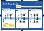
Summary of Contents for DVD-HR773

Page 1: ...Introducing Samsung DVD Recorder DVD HR773 HR775 HR777 Introducing Samsung DVD Recorder DVD HR773 HR775 HR777 Samsung Electronics Co LTD Digital AV Division...

Page 2: ...video playing recording using optical disc as the medium format High picture and sound quality recording capability comparing with analog medium recording systems Digital recording by an optical medi...

Page 3: ...recording Automatic empty area recording High Speed Search and Play 3 Qui ck dubbi ng W i t h t he qui ck dubbi ng f unct i on dat a t r ans f er f r om HDD t o DVD Di s c i s f as t er t han ever 4 A...

Page 4: ...uring subject movement which is characteristic of the conventional interlaced scanning method 50 Frame Sec 25 Frame Sec Recorded programs are shown as thumbnail pictures and information such as title...

Page 5: ...ssembly DVD HR773 consists of Deck Main PCB Jack PCB SMPS PCB PCB FRONT PCB HDD DECK Top Bottom Panel Ass y JACK PCB MAIN PCB SMPS PCB DECK LOADER TOP COVER BOTTOM HDD Power Cord FRONT PANNEL FRONT PC...

Page 6: ...Di s as s em bl y and Reas s em bl y pr oces s Top Cabi net Rem oval As s y Fr ont Cabi net Rem oval Har d Di s k Rem oval As s y Deck Mai n PCB S M P S PCB Rem oval FRONT AV PCB JACK PCB...

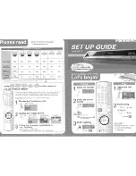
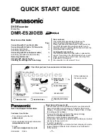
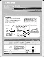
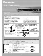
Page 7: ...Supplide Accessary DVD HR773 supply below accessary...

Page 8: ...Specifications...

Page 9: ...RW RW R RW RAM One Touch Recording Automated Quality Adjustment for Timer Recording Copying data from a digital camcorder using a DV input jack Selectable Recording Mode Recording Features Playing Fea...

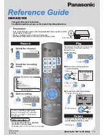
Page 10: ...1 Overall block diagram...

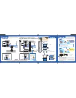
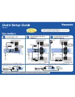
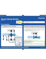
Page 11: ...2 Wiring diagram...

Page 12: ...3 B E DIGITAL Board H W I nt er f ace...

Page 13: ...m I nt er f ace Front Micom uPD78F0526 FIC1 NEC is used to control Power VFD Module MTS Block KEY Input Matrix etc The SPI Serial Peripheral Interface port provides a bus for a serial interface with A...

Page 14: ...5 Vi deo I nt er f ace...

Page 15: ...ased on video signal U1 is synchronous signals with decoded video signal The above signals which are CVBS Composite Video Burst Synchronized Y S_Video C S_Video Y Component G Green Cr component R Red...

Page 16: ...speed ADCs converters and A D conversion of 10bit analog Video signal converted into Digital Video signal ITU R656 Format is outputted via On CVBS and S video inputs the user can control video charact...

Page 17: ...7 A V SW I TCHI NG I C DVD HR773 has the one RCA Video input FRONT IN and two SCART Jack AV1 Scart jack IN CVBS AV2 Scart jack IN RGB Input CVBS AV3 RCA input in Front Panel...

Page 18: ...componect Y Pb Pr to IC216 Y pin31 C pin32 signals are superposed to composited video pin 17 and this signal outputted to Scart AV1 and composite RCA video S video and component video signals are inp...

Page 19: ...ersion of 10bit Video signal converted into analog signal is outputted via amplifer of analog part The above signals which are CVBS Composite Video Burst Synchronized Y S_Video C S_Video Y Component G...

Page 20: ...ite or component video output The digital input format includes 8 bit interleaved or 16 bit YCbCr 4 2 2 video The MS9411 ENCODER output can be in one of the following formats Baseband composite M NTSC...

Page 21: ...10 AUDI O...

Page 22: ...al S PDIF terminal switchig IC VIC1 A D coverter U1 MPEG Encorder Decoder So audio signal flows like this AV input Jack IC216 Mux switchig IC VIC1 A D coverter U1 MPEG Encoder Decorder Digital ouput o...

Page 23: ...11 St er eo Bi l i ngual MTS s um m ar y MTS SIGNAL mono Nicam Dual Nicam STEREO A2 Dual A2 STEREO A2 Germany Australia Nicam UK FRANCE...

Page 24: ...MTS s i gnal t abl e...

Page 25: ...the stereo and NICAM signal and send the detecting state to micom EIC1 and Front Micom FIC1 It will display the screen by OSD OSD On Scr een Di s pl ay 3 MTS processor decode the SIF signal and send...

Page 26: ...11 Tuner Dem odul at or Bl ock di agr am of Tuner...

Page 27: ...ncy signal interference from antenna LPF for VHF band remove UHF band signal HPF for UHF band remove VHF band signal Single Tune RF AMP Single Tune for receiving Channel initially RF AMP Gain control...

Page 28: ...circuits It have double balance mixer for removing interference MOP tuned the selected channel It is very important function in tuner MOP generate IF signal and connect to IF demodulator OSC OSCI LLA...

Page 29: ...at or Demodulate the IF signal for base band video and audio The demodulated video and audio signal go to AV processing go to MUX IC for AV input switching MUX Mul t i pl exer Bl ock di agr am of dem...

Page 30: ...rope samsungportal com 2 W rite the file to disc using the CD RWof your computer 3 Insert the update CD R disc with the software update Recommended Application Program Nero Burning Easy CD Creator etc...

Page 31: ...2 minutes to complete the update The message below will be displayed in the screen after update is completed and the tray will open automatically 4 Press the OK button on the remote control if the me...

Page 32: ...ee s pace on your HDD DVD R RW RAM di s cs Cannot pl ay t he di s c Checkpoi nt 1 Check t he r egi onal code of t he DVD di s c The di s c r evol ves but no i m age or bad qual i t y i m ages ar e di...

Page 33: ...agai n 2 Recor di ng wi l l be cancel l ed i f t he power i s i nt er r upt ed due t o a power f ai l ur e or anot her s i m i l ar r eas on whi l e r ecor di ng The r em ot e cont r ol does n t wor k...

Page 34: ...s normal level I2C singnals in IC216 pin16 18 are swinged between 0 5V 9 pin in CN1 of Jack PCB has normal level CVBS Vi deo out put er r or 4 6pin in CN2 of jack PCB has normal level I2C singles in I...

Page 35: ...s no Di gi t al Audi o Out Check Current Digital Audio Setting is PCM ChecK Digital Audio data pin29 of CN1 JACK PCB AV1 RGB Out put Er r or 10 12 14 pin in CN2 of Jack PCB has normal level Analog sig...

Reviews: