background image

DISHWASHER

CONTENTS

SERVICE

Manual

DISHWASHER

Model Name  :  DW80H9970US 
 

  DW80H9950US 


  DW80H9940US 


  DW80H9930US

Model Code  :  DW80H9970US/AA  DW80H9970US/AC
 

  DW80H9950US/AA  DW80H9950US/AC 


  DW80H9940US/AA  DW80H9940US/AC 


  DW80H9930US/AA  DW80H9930US/AC

1.  Safety Instructions

2. 

)HDWXUHVDQG6SHFL¿FDWLRQV

3.  Disassembly and Reassembly

4.  Troubleshooting

5.  PCB Diagram

6.  Wiring Diagram

7.  Reference

Summary of Contents for DISHWASHER

Page 1: ...9950US DW80H9940US DW80H9930US Model Code DW80H9970US AA DW80H9970US AC DW80H9950US AA DW80H9950US AC DW80H9940US AA DW80H9940US AC DW80H9930US AA DW80H9930US AC 1 Safety Instructions 2 3 Disassembly and Reassembly 4 Troubleshooting 5 PCB Diagram 6 Wiring Diagram 7 Reference ...

Page 2: ...tions 1 1 1 Safety Instructions for Service Engineers 1 5 2 1 Features 5 6 7 8 3 Disassembly and Reassembly 9 9 10 10 43 4 Troubleshooting 44 44 47 5 PCB Diagram 61 61 62 63 64 6 Wiring Diagram 65 65 7 Reference 66 66 67 68 69 ...

Page 3: ...Safety Instructions _ 1 1 SAFETY INSTRUCTIONS 1 1 SAFETY INSTRUCTIONS FOR SERVICE ENGINEERS ሪ ሪ Warning Caution Warning Before Servicing ࣃ ࣃ same time ࣃ ࣃ ࣃ ...

Page 4: ...2 _ Safety Instructions While Servicing ࣃ ࣃ parts ࣃ ࣃ ࣃ After Servicing ࣃ ࣃ ࣃ ...

Page 5: ...Safety Instructions _ 3 Caution Before Servicing ࣃ ࣃ ࣃ ࣃ During Servicing ࣃ ࣃ connections moisture from it ࣃ ...

Page 6: ...4 _ Safety Instructions After Servicing ࣃ ࣃ ...

Page 7: ...terwall cleaning system gets dishes sparkling everytime Targeted wash for hard to clean pots and pans Wash smaller loads without wasting water Removable roll up silverware tray for easy unloading Flexible design for more space Wash your dishes in less time Worry free dishwashing ...

Page 8: ...nozzle spray Dry type Air diffusion condensing dry system Power usage Main Pump 96w Waterwall operating Heater 1100w Standard amount of used water Size W D H Accessory parts User Installation manual Installation Kit Drain Hose Holder Drain Hose Hose Clamp Kick Plate 3rd Rack PAD Cutlery rack 3rd rack 3rd rack PAD Lower rack Upper rack Upper nozzle Door Base Dispenser Lower nozzle Water vane Contro...

Page 9: ...IONS WITH EXISTING MODELS Model NEW MODEL MODEL DW80H9950US DW80H9940US DW80H9970US DW80H9930US DW80F800UWS DW80F600UTS UTB UTW Photo Frame Front STS STS Sensors O O O O O 2 stage O O O O O Programs 6 6 5 6 4 Options 6 6 5 6 4 ...

Page 10: ...2 4 OPTIONS SPECIFICATIONS Photo Item Code QTY Remarks 1 1 1 1 1 1 1 1 ...

Page 11: ...Disassembly and Reassembly _ 9 3 DISASSEMBLY AND REASSEMBLY 3 1 TOOLS FOR REMOVAL AND REASSEMBLY Type 10mm Preparation for parts replacement Caution ...

Page 12: ...eassembly 3 2 PREPARATION FOR PARTS REPLACEMENT Warning Caution Before servicing make sure to remove all items from inside of the dishwasher including the wash racks 3 3 REMOVING THE UPPER RACK IF NEEDED Step 1 Step 2 Step 3 ...

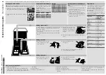
Page 13: ...Disassembly and Reassembly _ 11 Part Figure Description Main PBA Preparation remove it ...

Page 14: ...12 _ Disassembly and Reassembly Part Figure Description Inverter PBA Preparation ...

Page 15: ...Disassembly and Reassembly _ 13 Part Figure Description Door outer DW80H9950US DW80H9940US Preparation Caution ...

Page 16: ...14 _ Disassembly and Reassembly Part Figure Description Door outer DW80H9970US DW80H9930US Preparation Caution ...

Page 17: ...Disassembly and Reassembly _ 15 Part Figure Description Panel control DW80H9950US DW80H9940US Preparation ...

Page 18: ...16 _ Disassembly and Reassembly Part Figure Description Panel control DW80H9970US Preparation front ...

Page 19: ...Disassembly and Reassembly _ 17 Part Figure Description Panel control DW80H9970US ...

Page 20: ...18 _ Disassembly and Reassembly Part Figure Description Panel control DW80H9930US Preparation front ...

Page 21: ...Disassembly and Reassembly _ 19 Part Figure Description Panel control DW80H9930US Switch door Preparation ...

Page 22: ...20 _ Disassembly and Reassembly Part Figure Description Duct Dry system Assy Duct Condenser Assy Case Vent Assy Dry Duct Preparation section ...

Page 23: ...Disassembly and Reassembly _ 21 Part Figure Description Duct Dry system ...

Page 24: ...22 _ Disassembly and Reassembly Part Figure Description Dispenser slide Preparation Caution ...

Page 25: ...Disassembly and Reassembly _ 23 Part Figure Description Lever door ...

Page 26: ...24 _ Disassembly and Reassembly Part Figure Description Assy Case Brake Water Level Inlet Flow meter Outlet Assy case brake Preparation Caution Caution ...

Page 27: ...Disassembly and Reassembly _ 25 Part Figure Description Assy Motion UPPER NOZZLE MIDDLE NOZZLE LOWER NOZZLE WATER WALL Preparation 3 ...

Page 28: ...26 _ Disassembly and Reassembly Part Figure Description Assy Motion Caution ...

Page 29: ...Disassembly and Reassembly _ 27 Part Figure Description Assy Duct Nozzle Preparation 1 ...

Page 30: ...28 _ Disassembly and Reassembly Part Figure Description Drain Hose Preparation to separate ...

Page 31: ...Disassembly and Reassembly _ 29 Part Figure Description Water Valve Preparation section Caution Caution ...

Page 32: ...30 _ Disassembly and Reassembly Part Figure Description Cover base Preparation sensor connector 3 ...

Page 33: ...Disassembly and Reassembly _ 31 Part Figure Description Frame front Preparation Caution 2 3 unit ...

Page 34: ...32 _ Disassembly and Reassembly Part Figure Description Door Spring Preparation 1 2 ...

Page 35: ...Disassembly and Reassembly _ 33 Part Figure Description Assy Cover base Preparation Caution 1 2 ...

Page 36: ...34 _ Disassembly and Reassembly Part Figure Description Rear Leg Adjust bar Preparation 1 2 3 4 ...

Page 37: ...Disassembly and Reassembly _ 35 Part Figure Description Thermister Preparation 1 2 3 ...

Page 38: ...36 _ Disassembly and Reassembly Part Figure Description Turbidity sensor Preparation 1 2 Caution ...

Page 39: ...Disassembly and Reassembly _ 37 Part Figure Description Circulation pump Preparation 1 2 Caution 4 5 ...

Page 40: ...38 _ Disassembly and Reassembly Part Figure Description Base Preparation ...

Page 41: ...Disassembly and Reassembly _ 39 Part Figure Description Ass y Guide water Preparation Caution 3 4 ...

Page 42: ...40 _ Disassembly and Reassembly Part Figure Description Motor AC drive Switch micro Preparation Caution 1 2 Preparation Caution ...

Page 43: ...Disassembly and Reassembly _ 41 Part Figure Description Drain pump MOTOR BLDC PUMP Preparation 1 2 Caution ...

Page 44: ...42 _ Disassembly and Reassembly Part Figure Description Sump Preparation 1 sump 2 3 Caution ...

Page 45: ...HING SERVICE 1 Check the safety device 2 Use authentic Samsung replacement parts only 3 Handling wires 4 The state of screws and nuts 5 Remove foreign material 6 Check for water leakage 7 Check the power cable 8 Check leveling 9 Check the installation location ...

Page 46: ...der The Inverter PBA is out of order PE When the location is not detected for 2 minutes after the synchronous motor operation In Test Mode when the location is not detected for 1 minute In the cleaning section when the location is not detected for 3 minutes Draining 20 seconds on 5 seconds off is performed for 3 minutes The synchronous motor is out of order The location in the cam is incorrect tE ...

Page 47: ...tected after draining 20 seconds on 5 seconds off is performed for 3 minutes the drain pump is turned off If data over 3V is detected draining is performed for 3 minutes and then the sensed data is checked again There is a water leak OE for 5 seconds If sensor data over 3V is detected after draining 20 seconds on 5 seconds off is performed for 3 minutes the drain pump is turned off If data over 3V...

Page 48: ... The Circulation pump is out of order The Main PBA is out of order The Inverter PBA is out of order 4E5 When the number of detected water supply pulses are 200 at the Non water supply mode Repeats water valve on 1seconds off 1seconds 2 times Draining 20 seconds on 5 seconds off is performed for 3 minutes and then 200pulse over again detected repeat Draining The water valve is out of order 9E1 If b...

Page 49: ... operating the dishwasher the door must be closed If LE OE tE error occur enter Service Inspection Mode after resolving it Service Inspection Mode is described in the following table Item Related Parts Symptoms Description Entering Test Mode Changing the mode All Led Display n1 n2 n3 n4 n5 n6 n7 n8 n9 nA Repeats dE error occurs Displaying all Displaying the program version N1 nA Turbidity Error 32...

Page 50: ...ddle up run for 3 minutes n5 Distributor function Error The circulation motor runs BLDC 2600 RPM RPM display after operation circulation motor Each time press the Normal key it is possible to change the rpm 1200 3400rpm Each time press the Heavy key it is possible to change position of distributer 1 Middle Upper 2 Lower Right 3 Lower All 4 Lower Left n6 Distributor function Error The circulation m...

Page 51: ...ft Key Booster left LED On Drain pump Auto LED Circulation Motor low BLDC motor Normal LED Circulation Motor low BLDC motor Heavy LED Off Circulation Pump Runs Max 3 seconds to prevent damage c pump 3 Booster Right Key Booster Right LED On Distributer motor Auto LED Valve water Normal LED Heater Max operating 2seconds Heavy LED Vane CW Delicate LED Vane CCW Express LED Off ...

Page 52: ...move the connector before measuring Faulty Replace the Water Valve 6 Check whether the water supply stops after water is supplied for 20 seconds Faulty Replace the Water Valve and Flow Meter 7 Check whether the water supply stops after water is supplied for 80seconds or 5 minutes Check the water supply pressure 0 5bar Faulty Replace the Water Valve and Flow Meter 8 Check whether the Water Valve is...

Page 53: ...perating Faulty Replace the Main PBA assy 4 2 Check the operating LED red of the inverter PBA Normal Fully turn on while operating Faulty Replace the Inverter PBA assy 4 3 Check the operating voltage between 1 and 2 of the Inverter PBA CN8 connector at LA in test mode Normal 50V 90V while operating How to do LA in test mode Push Booster left key Booster right key Power key at the same time Push th...

Page 54: ... Circulation Pump 4 Check the operation of the Inverter PBA 4 1 Check the operating AC voltage of the Inverter PBA CN5 connector Normal 110V 120V while operating Faulty Replace the Main PBA assy 4 2 Check the operating LED red of the inverter PBA Normal Fully turn on while operating Faulty Replace the Inverter PBA assy 4 3 Check the operating voltage between 1 and 2 of the Inverter PBA CN6 connect...

Page 55: ...he Heater Relay on the base and the Black wire of the CN101 connector Normal 110 120V while operating Reconnect the Heater Relay connectors 4 Check the driving signals for the Heater Relay Measure the voltage between pin 1 D12 Anode side of the Main PBA RY201 relay and pin 2 of the CN402 connector When the Heater is off 10 5 to 13V When the Heater is operating 0 5V Faulty Replace the Main PBA assy...

Page 56: ... Micro switch On Short Micro switch Off Open Micro Switch sign alters in ON OFF state It is NG if keep in ON or OFF state for 120 seconds Do not supply with water and test Faulty Replace the Micro Switch for sensing positions Normal Replace the valve distributor and CAM switch 4 Adjust Cam A ssy and Find the faulty Faulty Replace Cam A ssy 5 Check whether half load is operating normally Check the ...

Page 57: ...duction between the Brown wire and the Black wire Sensor On 0V Sensor Off 5V Faulty Replace the Sensor vane for sensing positions Normal Replace the Motor vane and Sensor vane 4 Adjust Motion A ssy and Find the faulty Faulty Replace Motion A ssy 5 Check whether Motor vane is operating normally Check the Motor vane operation Normal 110 120V Check the operation of Motor vane Relay CCW Check the oper...

Page 58: ...sy Case Brake replace Thermistor Error tE 1 Check the connections for the Thermistor connector Reconnect the Thermistor connector 2 Check whether the Thermistor is operating normally Measure the voltage between both ends of the Thermistor Normal 0 05 to 4 95V Measure the resistance between both ends of the Thermistor Remove the connector before measuring See the Table right Thermistor table Temp ఁ...

Page 59: ...d continuously after method 2 Replace Main PBA Motor BLDC error 1E 1 Check the connections for the Pump BLDC connectors Reconnect the Pump BLDC connectors 3 Do it to act Test service test mode L2 L3 and motor water Faulty Replace motor 4 Problem occurrence to Method 1 2 3 Faulty Replace Main PBA BLDC Motor Communication error AE6 1 Check the connections between Main PBA CN401 connector and Inverte...

Page 60: ...rts and Reconnect the Sub PBA and Main PBA connectors 7 Check whether there is condensation on the PBA CN103 of Display Control Module connector CON100 TOUCH Module connector Normal No condensation Faulty Remove any condensation and moisture Normal Replace the Control Panel assy 8 Check whether the fuse is broken Replace the fuse 15A 9 Check the DC voltage of the Main PBA See Main PBA DC voltage e...

Page 61: ...ire connections for the Fan Motor Reconnect the Fan Motor connectors 2 Check the resistance of the Fan Motor coil Remove the connector before measuring Faulty Replace the Fan Motor assy 3 Check the operation of the Fan Motor Relay Check the operating voltage between the red wire of the CN201 connector and the Black wire of the CN101 connector Normal 110V 120V while operating Faulty Replace the Mai...

Page 62: ...ispenser connector 3 Check the resistance of the Dispenser Remove the connector before measuring Faulty Replace the Dispenser 4 Check the operation of the Dispenser Relay Check the operating voltage between the Black wire of the CN201 connector and the Black wire of the CN101 connector Normal 110V 120V while operating Faulty Replace the Main PBA assy No washing None 2 Check Rotors and ducts and va...

Page 63: ...ription 1 2 3 4 Sensing 5 6 7 Sensing 8 9 10 11 Description 12 13 14 15 16 17 18 19 Dry Fan motor 20 21 22 Description 23 24 25 26 27 28 29 30 31 32 33 34 1 2 3 4 5 6 7 33 32 8 31 34 30 29 28 27 26 25 24 23 22 21 20 19 18 16 15 14 9 10 13 17 12 11 3LQ ...

Page 64: ...62 _ PCB Diagram Description 1 2 3 Drain Pump Output 4 5 Writing Pin 6 7 5 1 6 7 2 3 4 5 2 INVERTER PBA 3LQ ...

Page 65: ...PCB Diagram _ 63 5 3 NEW PBA DETAILED SPECIFICATIONS AND DESCRIPTIONS FOR CONNECTORS AND RELAY TERMINALS MAIN PBA ሪ ሪ ሪ ሪ ሪ ሪ ሪ ሪ ሪ ሪ ሪ ሪ ሪ ሪ ...

Page 66: ...64 _ PCB Diagram ሪ ሪ ሪ ሪ ሪ 5 4 NEW PBA DETAILED SPECIFICATIONS AND DESCRIPTIONS FOR CONNECTORS AND RELAY TERMINALS INVERTER PBA ...

Page 67: ...Wiring Diagram _ 65 6 WIRING DIAGRAM 6 1 WIRING DIAGRAM Reference Information Abbreviated word Meaning Abbreviated word Meaning ...

Page 68: ...66 _ Reference 7 REFERENCE 7 1 MODEL NUMBER NAMING RULES DW 80 H 9 9 5 U 0 S 80 60 50 30 Counter Top 9 Premium 7 5 3 1 9 Super Premium 7 Premium 5 4 3 2 S F C Counter top S W 9 5 0 0 1 F 2013 2014 ...

Page 69: ...Reference _ 67 7 2 MODEL NUMBER NAMING RULES L R A S R A Z A Z A Z SR BB WD SL SD DW DW 9 9 7 5 3 1 3 6 5 4 3 3 8 Premium 6 4 3 2 7 7 5 3 1 Compact 9 Premium2 8 Premium1 7 6 5 4 3 2 1 ...

Page 70: ...68 _ Reference 7 3 MODEL NUMBER NAMING RULES AA U U B S F C AA AC DW DW F F G H I J 0 0 80 90 80 70 60 50 40 W S A O W R T D L H P SDP N E S S STSS B W V A 80 80 60 50 30 ...

Page 71: ...culation Motor 2 Drain Pump 3 Heater 4 Vent Fan 5 Flow Meter 6 Distributor 7 Dispenser 8 Tub Assy 9 Sump Assy 10 Tub Front Assy 11 Base Assy 12 Basket Assy 13 Top Middle Lower Nozzles 14 Case Brake 15 Door Lock Switch 16 Child Lock Unlock ...

Page 72: ... 2014 Samsung Electronics Co Ltd All rights reserved Printed in Korea GSPN GLOBAL SERVICE PARTNER NETWORK Area Web Site ...

Reviews: