Television Video Cassette Recorder
Chassis :
V15A
Model:
CXJ1331/TUCX
CXJ1931/TUCX
CXJ1352/TUCX
CXJ1952/TUCX
CXJ1364/TUCX
CXJ1964/TUCX
CXJ1353/TUCX
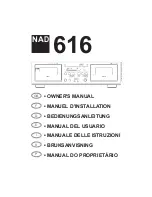
Television Video Cassette Recorder
CONTENTS
Precautions
Specifications
Alignment and Adjustment (VCR)
Alignment and Adjustment (TV)
Timing Chart
Troubleshooting
Exploded View and Parts List
Electric Parts List
Block Diagram
Wiring Diagram
PCB Layout
Schematic Diagrams
1.
2.
3.
4.
5.
6.
7.
8.
9.
10.
11.
12.
Summary of Contents for CXJ1331/TUCX
Page 2: ...ELECTRONICS Samsung Electronics Co Ltd MAR 1999 Printed in Korea 3V15A 1401 ...
Page 8: ...2 2 Samsung Electronics MEMO ...
Page 18: ...MEMO 3 10 Samsung Electronics ...
Page 28: ...MEMO 4 10 Samsung Electronics ...
Page 30: ...MEMO 5 2 Samsung Electronics ...
Page 48: ...MEMO 6 18 Samsung Electronics ...
Page 73: ...PCB Layout Samsung Electronics 11 3 11 3 Main CONTROL ...
Page 74: ...10 Wiring Diagram Wiring Diagram Samsung Electronics 10 1 ...
Page 77: ...Schematic Diagrams 12 3 Samsung Electronics 12 3 VCR POWER BLOCK ...