background image

COLOR MONITOR

SyncMaster 570B TFT (CN15MS*)

SyncMaster 580B TFT (CN15MO*)

Manual

SERVICE

COLOR MONITOR

CONTENTS

EXIT

MENU

AUTO

EXIT

MENU

AUTO

1. Precautions

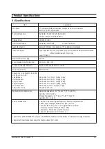
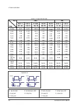
2. Product Specifications

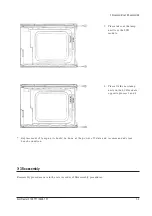
3. Disassembly & Reassembly
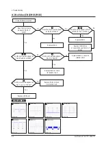
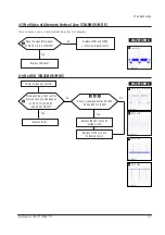
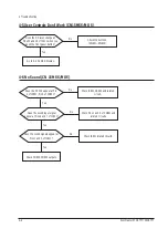
4. Troubleshooting

5. Exploded View & Parts List

6. Electrical Parts List

7. Block Diagram

8. Wiring Diagram

9. Schematic Diagrams

EXIT

MENU

AUTO

EXIT

MENU

AUTO

SyncMaster 570B TFT

SyncMaster 580B TFT

Summary of Contents for CN15MO series

Page 1: ...R CONTENTS EXIT MENU AUTO EXIT MENU AUTO 1 Precautions 2 Product Specifications 3 Disassembly Reassembly 4 Troubleshooting 5 Exploded View Parts List 6 Electrical Parts List 7 Block Diagram 8 Wiring Diagram 9 Schematic Diagrams EXIT MENU AUTO EXIT MENU AUTO SyncMaster 570B TFT SyncMaster 580B TFT ...

Page 2: ...es and Underwriters Laboratories UL Publication UL1410 59 7 Figure 1 1 Leakage Current Test Circuit 4 With the unit completely reassembled plug the AC line cord directly into a 120V AC outlet With the unit s AC switch first in the ON position and then OFF measure the current between a known earth ground metal water pipe conduit etc and all exposed metal parts including metal cabinets screwheads an...

Page 3: ...h ON Connect an insulation resistance meter 500 V to the blades of the AC plug The insulation resistance between each blade of the AC plug and accessible conductive parts see above should be greater than 1 megohm 6 Always connect a test instrument s ground lead to the instrument chassis ground before connecting the positive lead always remove the instrument s ground lead last 6 Do not remove a rep...

Page 4: ...x H with Standard base 385 4 x 364 7 x 173 mm 5 20kg 8 4kg MultiMedia base 385 4 x 406 2 x 179 mm 5 95kg 9 6kg Pivot MM base 385 4 x 406 2 x 179 mm 5 95kg 9 6kg Angle Pivot base 385 4 x 431 6 x 179 9 mm 6 6kg 9 8kg Wire frame base 385 4 x 339 2 x 79 7 mm 4 4kg 7 6kg Carton W x D x H 500 x 260 x 457 mm Environmental Considerations Operating Temperature 50 F to 104 F 10 C to 40 C Humidity 10 to 80 S...

Page 5: ...2 13 14 15 Red Green Blue GND GND DDC Return GND R GND G GND B No Connection GND Sync Self Test GND DDC Data H Sync V Sync DDC Data Red Green Blue GND GND DDC Return GND R GND G GND B No Connection GND Sync Self Test GND DDC Data H V Sync Not Used DDC Data Red Green H V Sync Blue GND GND DDC Return GND R GND G GND B Not Used GND Sync Self Test GND DDC Data Not Used Not Used DDC Data ...

Page 6: ...e Q Back porch R Active time E Front porch S Front porch VGA3 60 Hz 640 x 480 640 72 Hz 640 x 480 640 75Hz 640x480 800 56 Hz 800 x 600 800 60 Hz 800 x 600 VGA1 70 Hz 640 x 350 VGA2 70 Hz 720 x 400 Table 2 1 Timing Chart 31 469 31 777 3 813 1 589 26 058 0 318 70 087 14 268 0 064 0 858 13 155 0 191 28 322 Negative Positive Separate 31 469 31 778 3 813 1 589 26 058 0 318 59 940 16 683 0 064 0 794 15 ...

Page 7: ...tive Separate 49 726 20 110 1 117 3 910 14 524 0 559 74 551 13 414 0 060 0 784 12 549 0 020 57 284 Negative Negative Separate Mode MAC Timing Q R S P O Video Sync Sync Horizontal Vertical C D E P O B A Video Sync Sync Separate Sync C D A O E B P Video Sync Sync Video Q R S A Line time total B Horizontal sync width O Frame time total P Vertical sync width C Back porch D Active time Q Back porch R A...

Page 8: ...ssembly 6 Remove 5 screws on the Vesa Brkt from the Stand assembly 7 Remove cover hinge from the Stand assembly 8 Remove Stand Base from the Stand assembly 3 1 4 Pivot Multi media Stand Disassembly option 1 Stand the stand assembly with the base close to you 2 Remove the 4 screws on the back cover of the stand and remove it 3 Stand the stand assembly upside down 4 Remove the 4 screws 5 Disconnect ...

Page 9: ...9 Remove the Stand Base from the Stand Assembly 3 1 6 Wire frame stand Disassembly option 1 Carefully pull the cover hinge 2 Remove the cover vesa from the Stand assembly 3 Remove 4 screws on the assembly Bracket assembly 3 Disassembly and Reassembly 3 2 SyncMaster 570B TFT 580B TFT 1 After confirm there is nothing on the disk Turn the LCD module over and put it on a flat desk set to the ground 3 ...

Page 10: ... unit from the LCD module 4 Please fix the new lamp units on the LCD module opposite process 2 and 3 Replacement of lamp unit should be done at the power off state and recommanded clean bench condition 3 3 Reassembly Reassembly procedures are in the reverse order of Disassembly procedures ...

Page 11: ...MEMO 3 Disassembly and Reassembly 3 4 SyncMaster 570B TFT 580B TFT ...

Page 12: ...ng circuits No raster appears Audio PCB SMPS PCB Main PCB 12V develop but no screen Main PCB 12V does not develop Audio PCB SMPS PCB 4 If you push and hold the EXIT button for more than 5 seconds the monitor automatically turns back to the factory preset 4 1 No Power CN15MSS MOS Does proper DC 12 V appear at DC jack connected to CN101 Check SMPS or CN809 Yes No Does proper DC 3 3 V appear at Pin 4...

Page 13: ...rcuit Replace IC182 Replace IC181 SOG or check R181 and PIN 13 of CN102 No Does the clock pulse appear at Pin 84 of IC133 Does the H sync pulse appear at Pin 94 of IC133 Does the pulse appear at Pin 9 of IC182 or Pin 1 of IC181 5 Replace IC203 or check its related circuit Replace IC251 or check its related circuit No Do the sync pulses appear at Pins 30 and 31 of IC251 Do the sync pulses appear at...

Page 14: ... 4 4 No OSD CN15MSS MOS There is video but no OSD While pushing a front control button does any pulse appear at Pin 72 73 and 80 81 and 90 92 of IC203 8 No Do sync signals appear at Pins 203 204 and 207 of IC203 9 Replace IC251 10 Yes Replace IC203 or check its related circuit Replace IC133 or check its related circuit No 7 cn201 20 CH1 RMS 1 18V WAVEFORMS 8 IC203 72 73 80 81 90 92 CH1 RMS 2 2V WA...

Page 15: ...uts No Does the sound signals appear at Pins 1 and 3 of IC801 Check IC801 related circuits Yes No Does the sound input signal appear at Pins 6 and 7 of IC801 Check Pins 1 and 3 of CN801 and related circuits Yes 4 5 User Controls Don t Work CN15MSS MOS No Does the DC level change at Pins 35 and 36 of IC311 when you push the front panel button Check the buttons SW801 SW808 Yes Go to 4 4 No OSD Displ...

Page 16: ... connection between the PC and monitor secure Connect the cable between the PC and monitor Yes OK No Can you hear any sound from the Headphones Check CN802 on the Audio PCB and related circuit D805 D806 R811 R812 Yes No Is the Internal Microphone connector attached Check the connection between CN808 on the Audio PCB and the Internal Microphone Yes No Does the Internal Microphone work Check Q801 an...

Page 17: ...SyncMaster 570B TFT 580B TFT 5 1 5 Exploded View and Parts List 5 1 Simple Base CN15MSS ...

Page 18: ...5 Exploded View Parts List 5 2 SyncMaster 570B TFT 580B TFT 5 2 MultiMedia Base CN15MSS ...

Page 19: ...6 Exploded View Parts List SyncMaster 570B TFT 580B TFT 5 3 5 3 Pivot MultiMedia Base CN15MSS ...

Page 20: ...5 Exploded View Parts List 5 4 SyncMaster 570B TFT 580B TFT 5 4 Angle Pivot Base CN15MSS ...

Page 21: ...6 Exploded View Parts List SyncMaster 570B TFT 580B TFT 5 5 5 5 Wire Frame Base CN15MSS ...

Page 22: ...8 3x8 3x6 3mm C110 2409 001029 C ORGANIC 120uF 20 6 3V WT TP 10 3x10 3x10 3mm 9 C111 2402 000168 C AL SMD 100uF 20 16V GP TP 8 3x8 3x6 3mm C112 2203 000257 C CERAMIC CHIP 10nF 10 50V X7R TP 1608 C113 2402 000168 C AL SMD 100uF 20 16V GP TP 8 3x8 3x6 3mm C114 2203 000257 C CERAMIC CHIP 10nF 10 50V X7R TP 1608 C115 2402 000168 C AL SMD 100uF 20 16V GP TP 8 3x8 3x6 3mm C116 2203 000257 C CERAMIC CHIP...

Page 23: ... 10 50V X7R TP 1608 C160 2203 000257 C CERAMIC CHIP 10nF 10 50V X7R TP 1608 C161 2203 000257 C CERAMIC CHIP 10nF 10 50V X7R TP 1608 C162 2203 002398 C CERAMIC CHIP 22nF 10 50V X7R TP 1608 C163 2203 000257 C CERAMIC CHIP 10nF 10 50V X7R TP 1608 C164 2203 000140 C CERAMIC CHIP 1 5nF 10 50V X7R TP 1608 C165 2203 000257 C CERAMIC CHIP 10nF 10 50V X7R TP 1608 C166 2203 000357 C CERAMIC CHIP 0 15nF 5 50...

Page 24: ...00nF 10 16V X7R TP 1608 C220 2203 005005 C CERAMIC CHIP 100nF 10 16V X7R TP 1608 C221 2203 005005 C CERAMIC CHIP 100nF 10 16V X7R TP 1608 C222 2203 005005 C CERAMIC CHIP 100nF 10 16V X7R TP 1608 C223 2203 005005 C CERAMIC CHIP 100nF 10 16V X7R TP 1608 C224 2203 005005 C CERAMIC CHIP 100nF 10 16V X7R TP 1608 C225 2203 005005 C CERAMIC CHIP 100nF 10 16V X7R TP 1608 C226 2203 005005 C CERAMIC CHIP 10...

Page 25: ...132 0401 001056 DIODE SWITCHING MMBD4148SE 75V 600mA SOT 23 TP D133 0401 001056 DIODE SWITCHING MMBD4148SE 75V 600mA SOT 23 TP D134 0401 001056 DIODE SWITCHING MMBD4148SE 75V 600mA SOT 23 TP D301 0401 001056 DIODE SWITCHING MMBD4148SE 75V 600mA SOT 23 TP D302 0401 001056 DIODE SWITCHING MMBD4148SE 75V 600mA SOT 23 TP FT101 3301 001145 CORE FERRITE BEAD AB 4 5x1 6x1 6mm FT131 2901 001114 FILTER EMI...

Page 26: ...28X8BIT SOP 8P 150MIL 5V 10 PLASTIC 0 TO 70C 100UA CMOS TP IC373 0803 000122 IC TTL 74F125 BUFFER SOP 14P 150MIL Q L101 2703 001070 INDUCTOR SMD 100uH 10 4 5x3 2x3 2mm L102 2703 001070 INDUCTOR SMD 100uH 10 4 5x3 2x3 2mm L103 2703 001070 INDUCTOR SMD 100uH 10 4 5x3 2x3 2mm MP1 0 BN41 00033A PCB MAIN CN15LS FR 4 4 172 4 107 0 1 6 1 6T Q101 0501 002080 TR SMALL SIGNAL 2SC2412K NPN 200mW SOT 23 TP 1 ...

Page 27: ...hm 5 1 16W DA TP 1608 R318 2007 000074 R CHIP 100ohm 5 1 16W DA TP 1608 R319 2007 000074 R CHIP 100ohm 5 1 16W DA TP 1608 R320 2007 000074 R CHIP 100ohm 5 1 16W DA TP 1608 R321 2007 000074 R CHIP 100ohm 5 1 16W DA TP 1608 R322 2007 000074 R CHIP 100ohm 5 1 16W DA TP 1608 R323 2007 000109 R CHIP 1Mohm 5 1 16W DA TP 1608 R324 2007 000074 R CHIP 100ohm 5 1 16W DA TP 1608 R325 2007 000074 R CHIP 100oh...

Page 28: ...TP 1608 R974 2007 000120 R CHIP 680ohm 5 1 16W DA TP 1608 R975 2007 000074 R CHIP 100ohm 5 1 16W DA TP 1608 R976 2007 000084 R CHIP 4 7Kohm 5 1 16W DA TP 1608 RA131 2011 001015 R NETWORK 1Kohm 5 1 16W L CHIP 8P TP RA132 2011 001015 R NETWORK 1Kohm 5 1 16W L CHIP 8P TP RA133 2011 001015 R NETWORK 1Kohm 5 1 16W L CHIP 8P TP RA134 2011 001015 R NETWORK 1Kohm 5 1 16W L CHIP 8P TP RA135 2011 001015 R N...

Page 29: ...NER BZX84C5V1 5 1V 5 200mW SOT 23 ZD182 0403 000579 DIODE ZENER BZX84C5V1 5 1V 5 200mW SOT 23 ZD183 0403 000579 DIODE ZENER BZX84C5V1 5 1V 5 200mW SOT 23 ZD184 0403 000579 DIODE ZENER BZX84C5V1 5 1V 5 200mW SOT 23 ZD185 0403 000579 DIODE ZENER BZX84C5V1 5 1V 5 200mW SOT 23 ZD311 0403 000579 DIODE ZENER BZX84C5V1 5 1V 5 200mW SOT 23 6 Electrical Parts List 6 8 SyncMaster 570B TFT 580B TFT Loc No Co...

Page 30: ...39 00002A CBF HARNESS 60 BLU WHT 26 CIS BN39 00030A CBF SIGNAL DETACHABLE 1830MM 15P 15P 2990 D SUB MALE CN201 PAN BN39 00083A CBF HARNESS 20P 140MM UL1571 AWG30 DF14 20S 1 25C CIS BH39 10007A CBF POWER CORD DET H05VV F 250V 6A IVY 1830MM CIS BN44 00022A INVERTER SIC241T S 2LAMP 15 11 5 12 5 121 0 30 5 14 0 CIS BN68 00075H MANUAL USERS S M570B 580BTFT SAMSUNG E F S G P I R W W MIMOJO80G 148X210 I ...

Page 31: ...0B TFT SyncMasyer 570sTFT 580TFT 7 1 MXIC284 Frame Memory TDA2822M AudioAmp LVDS DS90C385 INVERTER 8MHz 14 3MHz R 8 8 G B HSYNC 12V_ADC 12V_INV 5V_S VCC 5V_PLL 3 3V_S 5V_FE 5V_ADC VSYNC PC MICOM VOLUME TONECTRL TDA8752 ADC Speaker BLOCK DIAGRAM ...

Page 32: ...SyncMaster 570B TFT 580B TFT 8 1 8 Wiring Diagram ...

Page 33: ...9 1 SyncMaster 570sTFT 580sTFT 9 Schematic Diagrams 9 1 ADC I O Part Schematic Diagram CN15MSS 3 5 4 ...

Page 34: ...9 Schematic Diagrams SyncMaster 570sTFT 580sTFT 9 2 3 IC133 31 CH1 RMS 2 12V 4 IC182 94 CH1 RMS 3 5V 5 IC182 9 CH1 RMS 3 1V ...

Page 35: ...9 2 FRC LVDS Part Schematic Diagram CN15MSS 9 Schematic Diagrams 9 3 SyncMaster 570sTFT 580sTFT 7 2 1 8 6 10 9 11 ...

Page 36: ...570sTFT 580sTFT 9 4 2 IC251 31 CH1 RMS 2 12V 7 IC251 141 CH1 RMS 2 3V 1 IC251 30 CH1 RMS 2 8V 6 IC203 1 CH1 RMS 4 56V 8 IC203 72 73 80 81 90 92 CH1 RMS 2 2V 10 IC203 207 CH1 RMS 3 6V 9 IC203 203 CH1 RMS 1 7V 11 IC203 204 CH1 RMS 3 6V ...

Page 37: ...9 3 Micom Part Schematic Diagram CN15MSS 9 Schematic Diagrams 9 5 SyncMaster 570sTFT 580sTFT 5V_S 12V_INV ...

Page 38: ...Samsung Electronics Co Ltd July 2000 Printed in Korea P N BN68 00097D 01 ...

Reviews: