Samsung CL17M2MQZX/STR, Service Manual
The Samsung CL17M2MQZX/STR, a top-of-the-line monitor, delivers stunning visuals with its high-resolution display. Ensure optimal performance and troubleshoot issues effortlessly with our Service Manual. Download this comprehensive manual for free from manualshive.com, and unlock the full potential of your Samsung CL17M2MQZX/STR.
Share
Download


Reviews:
No comments
Related manuals for CL17M2MQZX/STR

Omnivision VHS PV-C1324
Brand: Panasonic Pages: 4

OmniVision PV-C1324-K
Brand: Panasonic Pages: 8

Omnivision VHS PV-M2046
Brand: Panasonic Pages: 32

UW-17J11VD
Brand: Samsung Pages: 82

28
Brand: Radio Shack Pages: 44
MC132EMG - 13' Tv/vcr Combination
Brand: Magnavox Pages: 2

27MDTR20 - Tv/dvd/vcr Combination
Brand: Magnavox Pages: 4

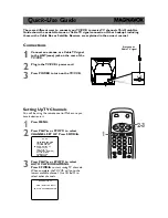
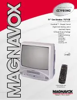
CC19B1MG
Brand: Magnavox Pages: 60

MWC24T5
Brand: Magnavox Pages: 82

MC132EMG/17
Brand: Magnavox Pages: 88

14H3 T1
Brand: Daewoo Pages: 54

WTV11321B
Brand: White-Westinghouse Pages: 32

VV-1309
Brand: Quasar Pages: 44

MGT204D
Brand: Magnavox Pages: 104

W6313CC
Brand: Sylvania Pages: 32

F14H3
Brand: Daewoo Lucoms Pages: 54

GB14H1T
Brand: Daewoo Pages: 23
CC19B1MG
Brand: Magnavox Pages: 2


