background image

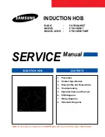
INDUCTION HOB

SERVICE

Manual

INDUCTION HOB

CONTENTS

1.  Precaution

2.  Product Specification

3.  Disassembly and Reassembly
4.  Troubleshooting
5.  Exploded Views and Part List
6.  PCB Diagrams
7.  Wiring Diagrams
8.  Schematic Diagrams

Refer to the service manual in the GSPN(see rear cover) for the more information.

BASIC 


C61R1AAMST

MODEL   

CTI613EHST

MODEL CODE  : 

CTI613EHST/XEF

INDUCTION HOB

Summary of Contents for C61R1AAMST

Page 1: ...on 3 Disassembly and Reassembly 4 Troubleshooting 5 Exploded Views and Part List 6 PCB Diagrams 7 Wiring Diagrams 8 Schematic Diagrams Refer to the service manual in the GSPN see rear cover for the more information BASIC C61R1AAMST MODEL CTI613EHST MODEL CODE CTI613EHST XEF INDUCTION HOB ...
Page 2: ...r 13 4 Troubleshooting 14 4 1 Part Checking method 14 4 2 Failure Codes 15 4 3 Electrical Malfunction 25 5 Exploded Views and Parts List 27 5 1 Exploded Views 27 5 2 Main Parts List 28 5 3 Assy Working Coil Parts List 29 5 4 Assy Induction Module Parts List 30 5 4 Standard Parts List 31 6 P C B Diagrams 32 6 1 P C B Diagrams ASSY PCB PARTS 32 6 2 P C B Diagrams ASSY TOUCH PCB 33 6 3 P C B Diagrams...

Page 3: ... is properly grounded See the installation instructions that originally accom panied the product for proper grounding proce dures 5 The ventilation gap between the worktop and front of the unit underneath it must not be covered 6 Before connecting check that the nominal voltage of the appliance that is the voltage stated on the rating plate corresponds to the available supply voltage The rating pl...

Page 4: ...n Design 4 side STSS 4 side STSS Electric Features Burner Power Front Left 1 800W 1 400W Boost 2 000W Rear Left 1 200W 2 200W Boost 3 200W Front Right 1 200W 1 800W Boost 2 600W Rear Right 1 800W 1 800W Boost 2 600W 2 2 Features The Principle of Induction Heating When you place your cookware on a cooking zone and you turn it on the electronic circuits in your induction hob produce induced currents...

Page 5: ...5 level Boost Yes Power Pre Selection Yes 2 Specifications 2 3 Table of Specification Basic model New model Electrical Connection Rated voltage 220 240V 50 60Hz 220 240V 50 60Hz Mains connection 2N 380 415V 50 60Hz 2N 380 415V 50 60Hz 1N 220 240V 50 60Hz 1N 220 240V 50 60Hz Output Power MAX 5 500 6 500W MAX 7 200W Outside Dimensions WxLxH 575 x 505 x 55mm 575 x 505 x 62mm Net Weight 7 5Kg 12 0Kg G...

Page 6: ... 2 4 Accessory Screw DG97 00010A Installation Bracket DG61 00005B Power Cable DG96 00061B ...

Page 7: ... Top Plate to the Assy Case Burner 3 Raise the Assy Top Plate 4 After replacement of the Assy Top Plate Screw the Assy Top Plate to the Assy Case Burner Parts Explanation Photo Explanation Assy Control Panel double faced tape 1 Lift up the Assy Touch PCB Assy Touch PCB is fixed by double faced tape 2 Disconnect all sub wire 3 Replace the Assy Touch PCB or Control Panel Attention The Ceramic Glass ...

Page 8: ...Photo Explanation Assy Working Coil 1 Bend the Cover Coil a little 2 Lift up the Cover Coil from the hook 3 point bending bending Assy Working Coil C Cover Coil C Adiabatic Coil C Assy Working Coil A Cover Coil A Adiabatic Coil A Assy Working Coil B Cover Coil B Adiabatic Coil B ...

Page 9: ...ken 4 Disconnect all lead wires from the Assy Working Coil 5 For the replacement of Sensor Top pull the Sensor Top toward bottom side 6 Rotate the Sensor Wire by 90degree until the Sensor Top can be remove from the Coil Working 6 Rotate the Spring ETC Base by 90degree in order to replace 3 3 Replacement of the Assy Working Coil pull rotate pull rotate ...

Page 10: ...Sensor Top wire according to carved wire color guide warning Wire connecting position is very improtant Please keep attention 3 3 Replacement of the Assy Working Coil wire color guide wire color guide RD marking RD marking BL marking BL marking WH marking WH marking BK marking BK marking ...

Page 11: ...et Wire A 1 Remove the screw 2 Pull the Bracket Wire A toward front side 3 Lift up the Bracket Wire A 4 Replace the Bracket Wire A or sub wire warning Wire can be damaged when the repalcement of Bracket Wire A Please keep attention Screw Screw Screw Screw pull lift up pull lift up ...

Page 12: ... is very improtant Please keep attention 4 Remove the screw upper side securing the Assy Inverter Module to the Case Induction A screw 1 type 6002 000630 M3 L8 PCB marking is carved at the side of screw 3 5 Replacement of the Assy Induction Module wire connection guide wire connection guide Blue wire Blue wire Brown wire Brown wire Assy Inverter Module L Assy Inverter Module L Assy Inverter Module...

Page 13: ...e 5 Remove the 2 screw 6 Pull the Assy Inverter Module L R toward left or right side 7 Replace the Assy Inverter Module L R 8 Arrange Assy Inverter Module L R to proper position Please see the picture 9 Connect the sub wire with matched color position Please see the picture 10 After replacement arrange all wire properly by using Holder Wie Saddle 11 Especially wire of Assy Inverter Module L R must...

Page 14: ...g Coil wrong cooking zone will be operated when costomer start the cook 12 Remove the 1 screw at Motor DC bottom side screw 2 type 6006 001170 M4 L10 Ground screw 13 Remove the 2 screws at Motor DC upper side FM marking is carved at the upper side screw 3 type 6002 001321 M5 L10 14 Replace the Motor DC screw 2 screw 2 screw 3 screw 3 screw 3 screw 3 ...

Page 15: ...using small flat type screw driver 2 Disconnect the power cable 3 After replacement of Terminal Block connect the power cable properly 4 Connect the inner side of Terminal Block s wire properly 220 240V 220 240V 220 240V 380 415V IN L Brown N Blue PE Green wire connection guide wire connection guide Blue wire Blue wire Brown wire Brown wire ...

Page 16: ...Troubleshooting 4 1 Part Checking method Parts Photo Good No Good Sensor Top 7 65KΩ 9 34KΩ at 25 C The others Motor DC 1 65K 1 8KΩ between No 1 pin and No 3 pin The others Coil Working 0 01 1Ω 100MΩ exceed 14 ...

Page 17: ...0 19 Page 4 2 2 Safety Error Error Code Gerneral Function Solution Page Touch Button Short Error It occurs when the control panel s sensor field is shorted more than 10 seconds ex No 1 Place a damp cloth on the control panel No 2 Liquid boils over and lands on the control panel No 3 More than one key is pressed more than 10 seconds No 4 Defective Assy Touch PCB 20 Page Low Voltage Error It occurs ...

Page 18: ... wire connected properly by burner position Is the sensor s real resistance is opened circuit Connect the sensor Replace the wire Connect the wire properly S W Error Is the sensor connected The sensor has defect Replace the sensor Replace the Assy Touch PCB Perform the operation again and check if it is working properly After Power On does the symptom continue 4 2 3 ...

Page 19: ...r Is the sensor s real resistance is shorted circuit Remove any foreign substance from the shorted part S W Error Is the sensor terminal part of the PCB shorted The sensor has defect Replace the sensor Replace the Assy Touch PCB Perform the operation again and check if it is working properly After Power On does the symptom continue YES 4 2 4 ...

Page 20: ...erter Module to Assy Touch PCB The sensor has defect Replace the Assy Inverter Module PCB Replace the Assy Inverter Module PCB Perform the operation again and check if it is working properly After Power On does the symptom continue NO Is the sensor s real resistance is opened circuit check if the sub wire is damaged if the housing is inserted into the connector of the PCB Good condition 10kΩ at 25...

Page 21: ...erter Module to Assy Touch PCB The sensor has defect Replace the Assy Inverter Module PCB Replace the Assy Inverter Module PCB Perform the operation again and check if it is working properly After Power On does the symptom continue NO Is the sensor s real resistance is shorted circuit Good condition 10kΩ at 25 C check if the sub wire is damaged if the housing is inserted into the connector of the ...

Page 22: ...working properly S W Error Is the key not recognized after cleaning the control panel Is the key recognized intermittently Assy Touch PCB is defective Replace the Assy Touch PCB Is the key not recognized at all After Power On does the symptom continue Replace the sub wire or Assy Touch PCB 4 2 7 ...

Page 23: ...wire S W Error Is the sub wire connected from Assy PCB Parts to Assy Touch PCB Assy PCB Parts has defect Replace the Assy PCB Parts Replace the Assy PCB Parts Perform the operation again and check if it is working properly After Power On does the symptom continue NO Is the SMPS s DC line has some shorted circuit or opened circuit 4 2 8 ...

Page 24: ...ol Ceramic glass s surface Connect the wire properly S W Error Is the hob operated with empty cookware The Top sensor has defect Replace the sensor Replace the Assy Touch PCB Perform the operation again and check if it is working properly After Power On does the symptom continue YES Is the Top sensor s real resistance is opened circuit ...

Page 25: ...ll size aluminium etc Place the cookware Place the suitable cookware S W Error Is the hob operated with no cookware Replace the Assy Inverter Module or Assy Touch PCB or Check the PCB Wiring Perform the operation again and check if it is working properly After Power On does the symptom continue YES ...

Page 26: ...erence at rotor or blade of Motor Connect the Motor wire Remove the interference at Motor S W Error Is the Motor wire connected Replace the Assy PCB Parts or DC Motor Perform the operation again and check if it is working properly After Power On does the symptom continue NO ...

Page 27: ...minal block connections Check the circuit breaker Replace or Repair the wiring Troubleshooting Heating Check the relay terminal voltage 220V 240V NO YES YES NO Heating Failure Check the wiring NO Check the all IGBT terminal resistance G E G C E C Is there any shorted circuit Perform the PCB failure process Repair the relay or missing circuit component Replace or Repair the wiring Replace the Assy ...

Page 28: ...V 12V Check the Assy Inverter Module Assy Touch PCB s input voltage 5V 12V GND Reset the circuit braker or check main power Repair Faulty wiring or PCB check Check Terminal block voltage 220V 240V Repair the relay or replace PCB Do all relays operate Replace PCB Replace PCB Troubleshooting PCB failure Replace or Repair the wiring YES YES NO NO YES YES YES NO NO NO ...

Page 29: ... Exploded Views and Parts List 5 1 Exploded Views R181 R182 R182 R183 M372 C005 C061 C266 C265 R073 G005 Z029 P218 M015 M060 W042 Front Left Rear Left Right C061 M056 R059 H042 M416 M418 M417 M417 G001 C001 ...

Page 30: ... SA M056 DE63 00005A CUSHION HVT MW5896W EPDM T5 W24 7 L40 BL 1 SNA M060 DG97 00010A ASSY HARD WARE C61RCCNR NO FRAME 1 SA M372 DE96 00747B ASSY TOUCH CT1613 CT7000 0990 AMBER 310x 1 SA M416 DG62 00028A ADIABATIC COIL A CTI613EHST S F INSULATI 1 SA M417 DG62 00029A ADIABATIC COIL B CTI613EHST S F INSULATI 2 SA M418 DG62 00030A ADIABATIC COIL C CTI613EHST S F INSULATI 1 SA P218 DG61 00005B BRACKET ...

Page 31: ... A 160pi 1400W 97uH 10 Ba 1 SA R082 DG27 01004A COIL WORKING B 180pi 1800W 78uH 10 Ba 2 SA R083 DG27 01005A COIL WORKING C 210pi 2200W 62uH 10 Ba 1 SA R181 DG96 00088A ASSY WORKING COIL A CTI613EHST 1 1 SA R182 DG96 00087A ASSY WORKING COIL B CTI613EHST 1 2 SA R183 DG96 00086A ASSY WORKING COIL C CTI613EHST 2 1 SA M054 R082 R082 R082 M054 M054 M054 R082 28 R081 R181 R183 R181 ASSY WORKING COIL A R...

Page 32: ...L WIRE M180 DG31 00011A MOTOR DC D12F 12BM 06 CTI613EHST 0 83A 1 SA M183 DG96 00091A ASSY INVERTER MODULE L CTI613EHST 1 SA M184 DG96 00092A ASSY INVERTER MODULE R CTI613EHST 1 SA R073 DG96 00085A ASSY INDUCTION MODULE CTI613EHST 1 SA W002 DG96 00089A ASSY WIRE HARNESS A CTI613EHST 230V50Hz 1 SA W004 DG96 00096A ASSY WIRE HARNESS C CTI613EHST 230V50Hz 1 SA INVERTER MAIN PCB W033 DG96 00090A ASSY W...

Page 33: ...SNA EARTH 1 3 6002 000217 SCREW TAPPING TH 1 M4 L8 ZPC WHT SW 6 SNA SUPPORT HEATER 1 2 6002 000217 SCREW TAPPING TH 1 M4 L8 ZPC WHT SW 9 SNA PCB GUIDE AIR 1 2 6002 000630 SCREW TAPPING PH 2S M3 L8 ZPC YEL SWR 2 SNA HEAT SINK 1 2 6002 001321 SCREW TAPPING PWH 2S M5 L10 ZPC YEL 2 SNA DC MOTOR 1 2 6006 001170 SCREW TAPPING TH WT TC M4 L10 ZPC WHT 1 SNA DC MOTOR 1 2 6002 000216 SCREW TAPPING TH 1 M4 0...

Page 34: ...ine input line 4 RY202 Main Relay Relay for L2 line input line 5 RY203 DC Motor Relay Low Relay for DC Motor control low fan 6 RY204 DC Motor Relay High Relay for DC Motor control high fan 7 T302 Terminal L1 line input from Terminal Block 8 T304 Terminal L2 line input from Terminal Block 9 T301 303 Terminal N line input from Terminal Block 10 T306 Terminal L1 line to Assy Inverter Module R 11 T305...

Page 35: ...and Rule 1 CON1 Main PCB wire connector communication wire connector to Assy PCB Parts 2 CON3 Top Sensor wire connector sensor wire connector to Sensor Top 3 CON4 Inverter PCB connector communication wire connector to Assy Inverter Module 4 CON5 MICOM Program connector MICOM program input port not connected 5 U7 MICOM Main MICOM 6 BZ1 Buzzer Beep Sound ...

Page 36: ...al AC voltage input terminal 3 OUT1 2 Working Coil wire High frequency AC voltage output wire right circuit 4 OUT3 4 Working Coil wire High frequency AC voltage output wire left circuit 5 D100 Bridge IC Full bridge rectifier IC 6 Q101 102 IGBT IC High frequency switching IC right circuit 7 Q201 202 IGBT IC High frequency switching IC left circuit 8 TH101 IGBT NTC sensor Thermistor for IGBT temp ri...

Page 37: ... 35 7 Wiring Diagrams This Document can not be used without Samsung s authorization 7 1 Wiring Diagrams ...

Page 38: ... 2 4 D 1 E S5 5 6 S6 7 S7 S8 8 C301 1 5uF 1 2 TNY280PN IC101 B PC817 PC101 4 3 L304 C40B14 P16 34T G5T 1A 12VDC RY204 470uF C109 4 5 6 7 8 9 10 11 12V SMW250 11V_WHT CN101 1 2 3 R110 200K KRA226 AT TR204 T304 100nF C201 C107 1nF 1nF C104 100 R201 PC817 4 3 1 2 R112 PC102 1K R107 200K ZNR301 470V 10D471 1uF R203 27 UZ5 6BSB ZD102 C105 100nF C205 2K R206 10uF C102 10D471 D101 1N4007 ZD101 470V ZNR30...

Page 39: ... P51 SDA 53 P50 SCL 52 P17 PDO6 PWM6 PPG6 TC6 51 P16 PDO5 PWM5 TC5 50 P15 INT3 TC2 49 TP40 TP TP40 TP 1 R11 220 R11 220 R54 5 6K F R54 5 6K F TP67 TP TP67 TP 1 TP84 TP TP84 TP 1 R6 2K R6 2K R45 2k R45 2k R8 220 R8 220 TP39 TP TP39 TP 1 TP58 TP TP58 TP 1 R17 1K F R17 1K F C6 22pF C6 22pF TP88 TP TP88 TP 1 TP73 TP TP73 TP 1 TP37 TP TP37 TP 1 TP79 TP TP79 TP 1 R51 2k R51 2k TP90 TP TP90 TP 1 C5 22pF ...

Page 40: ... 38 8 Schematic Diagrams 8 3 Schematic Diagrams ASSY INVERTER MODULE PCB This Document can not be used without Samsung s authorization ...

Page 41: ...w GSPN Global Service Partner Network Contry Web Site North America service samsungportal com Latin America latin samsungportal com CIS cis samsungportal com Europe europe samsungportal com China china samsungportal com Asia asia samsungportal com Mideast Africa mea samsungportal com Samsung Electronics Co Ltd October 2008 Printed in Korea Code No DE68 05052A ...

Reviews: