


INDOOR UNIT
SH09AWH
SH09ZWH
AQ09WHWE
KFR-25G/SWA
SH12AWH
SH12ZWH
AQ12WHWE
KFR-35G/SWA
OUTDOOR UNIT
SH09AWHX
SH09ZWHX
UQ09WHWE
KFR-25W/SWA
SH12AWHX
SH12ZWHX
UQ12WHWE
KFR-35W/SWA
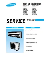
SERVICE
Manual
CONTENTS
AIR CONDITIONER
1. Product Specifications
2. Disassembly and Reassembly
3. Set Up the Model Option
4. Exploded Views and Parts List
5. Block Diagram
6. Schematic Diagram
ROOM AIR CONDITIONER
DB98_15924A(2)_co 04/3/8 11:22 AM Page 3
Summary of Contents for AQ12WHWE
Page 28: ...MEMO 27 Samsung Electronics ...
Page 29: ...MEMO Samsung Electronics 28 ...