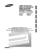
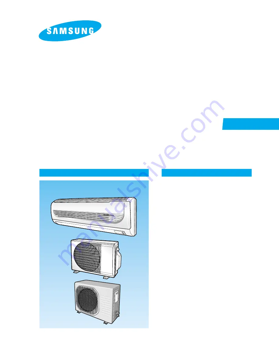
INDOOR UNIT
AQ12WHWE
OUTDOOR UNIT
UQ12WHWE
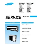
SERVICE
Manual
CONTENTS
AIR CONDITIONER
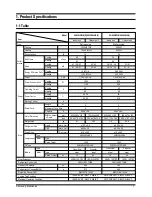
1. Product Specifications
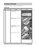
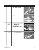
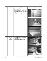
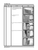
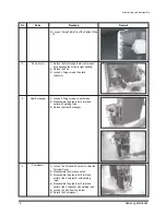
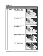
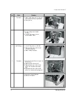
2. Disassembly and Reassembly
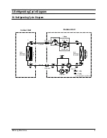
3. Refrigerating Cycle Diagram
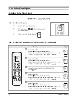
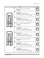
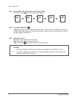
4. Set Up the Model Option
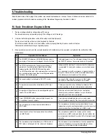
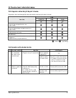
5. Troubleshooting
6. Exploded Views and Parts List
7. Block Diagram
8. Wiring Diagram
9. Schematic Diagram
ROOM AIR CONDITIONER
DB98_16569A(2)_co 4/6/04 2:57 PM Page 3
AQ09W8WE UQ09W8WE
SH12ZWHD SH12ZWHDX
SH09ZW8X
AQ12WHWED UQ12WHWED
SH09ZW8