background image

COLOR MONITOR

AP17K*
AP17J*

Manual

SERVICE

COLOR MONITOR

CONTENTS

1. Precautions

2. Product Specifications

3. Disassembly & Reassembly

4. Alignment & Adjustments

5. Troubleshooting

6. Exploded View & Parts List

7. Electrical Parts List

8. Block Diagram

9. Wiring Diagram

10. Schematic Diagrams

Summary of Contents for AP17J series

Page 1: ...ICE COLOR MONITOR CONTENTS 1 Precautions 2 Product Specifications 3 Disassembly Reassembly 4 Alignment Adjustments 5 Troubleshooting 6 Exploded View Parts List 7 Electrical Parts List 8 Block Diagram 9 Wiring Diagram 10 Schematic Diagrams ...

Page 2: ... all protective devices such as nonmetallic control knobs insulating materials cabinet backs adjustment and compartment covers or shields isolation resistor capacitor networks mechanical insulators etc 3 Leakage Current Hot Check Figure 1 1 WARNING Do not use an isolation transformer during this test Use a leakage current tester or a metering system that complies with American National Standards I...

Page 3: ...istance between each blade of the AC plug and accessible conductive parts see above should be greater than 1 megohm 7 Never defeat any of the B voltage interlocks Do not apply AC power to the unit or any of its assemblies unless all solid state heat sinks are correctly installed 8 Always connect a test instrument s ground lead to the instrument chassis ground before connecting the positive lead al...

Page 4: ...ync Signal Separate Sync TTL level positive negative Maximum Pixel Clock rate 110 MHz 185 MHz Active Display Horizontal 312 mm 4 mm Vertical 234 mm 4 mm Input Voltage AC 90 264 Volts 60 Hz or 50 Hz 3 Hz Power Consumption 90 Watt max 100 Watt max Dimensions W x D x H Unit 15 7 x 16 2 x 15 7 Inches 398 x 412 x 400 mm Carton 20 4 x 22 8 x 18 42 Inches 517 x 580 x 468 mm Weight Net Gross 35 1 lbs 15 9...

Page 5: ...e 2 2 Male Type Sync Type Pin No Macintosh Separate 1 2 3 4 5 6 7 8 9 10 11 12 13 14 15 Red Green Blue N C DDC Return GND R GND G GND B N C GND Sync Self raster N C DDC Data H Sync V Sync DDC Clock GND R Red H V Sync Sense 0 Green GND G Sense 1 Reserved Blue Sense 2 GND V Sync GND B GND H Sync ...

Page 6: ...itive Separate 31 469 31 778 3 813 1 907 25 422 0 636 59 940 16 683 0 064 1 048 15 253 0 318 25 175 Negative Negative Separate 37 500 26 667 2 032 3 810 20 317 0 508 75 000 13 333 0 080 0 427 12 800 0 027 31 500 Negative Negative Separate 43 269 23 111 1 556 2 222 17 778 1 556 85 008 11 764 0 671 0 578 11 093 0 023 36 000 Negative Negative Separate 46 875 21 333 1 616 3 232 16 162 0 323 75 000 13 ...

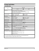
Page 7: ...2 Product Specifications 2 4 AP17K AP17J Memo ...

Page 8: ...de of the monitor till it makes a ttak sound 2 grooves Left and Right Make sure each snap is disengaged 5 Pull the Rear Cover up off the monitor AP17K AP17J 3 1 3 Disassembly and Reassembly This section of the service manual describes the disassembly and reassembly procedures for the AP17K AP17J monitor WARNING This monitor contains electrostatically sensitive devices Use with caution when handlin...

Page 9: ...onnector on the Main 5 Using the jig release the snaps 2 connecting the Front Cover and the PCB then lift up the Bottom to separate the two Shield 6 Disconnect the Tilt connector at the CN2 CN22 connector on the Main PCB 7 Disconnect the Sub PCB connector at the CN201 connector on the Main PCB 8 Remove the screws on the back and along each side of the Bottom Chassis 9 Carefully lift the Main PCB A...

Page 10: ...pment The following equipment may be necessary for adjustment procedures 4 1 2 a DISPLAY CONTROL ADJUSTMENT 1 Non metallic screwdriver 1 5 2 5 3 mm 2 Non metallic screwdriver 1 5 2 5 3 mm 3 Digital Multimeter DMM or Digital Voltmeter 4 Signal generator or DM200 software 5 Personal computer 4 1 2 b COLOR ADJUSTMENTS 1 All equipment listed in 4 1 2 a above 2 Color analyzer or any luminance measureme...

Page 11: ...h pattern Brightness Maximum Contrast Maximum Click Standard Dump on the right Menu in the general field Use control bar after selecting size B in the left Menu to adjust the horizontal size of the display Pattern to 312mm Tolerance 3mm Run the All Mode save in the Right Menu Caution Do not Run the All mode Save at the other scannig times except for 1024x768 68kHz 85Hz 4 2 4 b VERTICAL SIZE ADJUST...

Page 12: ...he tolerance range Use control bar after selecting V LINEARITY BAL in left menu to optimize the image 4 2 5 Trapezoid Adjustment CONDITIONS Scanning frequency 68 kHz 85 Hz Display image Crosshatch pattern Brightness Maximum Contrast Maximum Use control bar after selecting TRAPEZOID in left menu to make the image area rectangular Figure 4 4 Trapezoid 4 2 6 Pinbalance Adjustment CONDITIONS Scanning ...

Page 13: ...8 kHz 85 Hz Display image Crosshatch pattern Use control bar after selecting PINCUSHION in left menu to straighten the sides of the image area 4 2 9 Degauss No adjustments are available for the degaussing circuit The degaussing circuit can effectively function only once per 30 minutes 4 2 10 To Delete the User Mode Data To delete the adjustment data from the user modes click 4 USER DELETE in right...

Page 14: ...the luminance of the back raster to between 0 5 to 0 7 ft L using contron bar after selecting GREEN CUTOFF in the menu 3 Use control bar after selecting BLUE CUTOFF in left menu to set the y coordinate to 0 298 0 02 4 Use control bar after selecting RED CUTOFF in left menu to 0 283 0 02 If color values would not be matched desirable values repeat sequence 3 and 4 after readjusting GREEN CUTOFF con...

Page 15: ...to 4 3 2 a and readjust all settings 2 Display a full white pattern 3 Select Geometry in softjig menu 4 Select 7 5 ft in right menu 5 Check whether the white coordinates of the video meet the above coordinates spec 6 Select 8 24 ft in right menu 7 Check whether the white coordinates of the video satisfies the above spec If they do not return to 4 3 2 a and readjust all settings Select Color and cl...

Page 16: ...he display area Note Color purity adjustments should only be attempted by qualified personnel PROCEDURE For trained and experienced service technicians only Use the following procedure to correct minor color purity problems 1 Make sure the display is not affected by external magnetic fields 2 Make sure the spacing between the PCM assembly and the CRT stem is 29 mm 1 mm 3 Display a green pattern ov...

Page 17: ...4 Alignment and Adjustments 4 8 AP17K AP17J Memo ...

Page 18: ...zontal output circuits 5 1 1 No Power Supply Chirping noise exists Check and replace IC601 Check and replace D601 and FH1 Done No Yes Repeating start Check and replace D606 No Yes IC601 Pin 1 waveform is right Check and replace D614 IC601 Q602 and ZD601 Yes No C622 Voltage is 13 V 0 5V Check and replace IC201 IC301 IC401 Q402 and Q404 Yes Yes No Operate normally Replace Main board Verify voltages ...

Page 19: ...nc power off mode Check signal source H V Sync video level LED blinks Check IC201 Pin 40 Yes No 12 V line off Check IC201 Pin 6 Yes No IC601 Pin 1 output voltage exists Refer to 5 1 1 No Power Supply Done Yes No 2 WAVEFORMS 2 100 V IC601 1 CH1 P P 100 V CH1 RMS 325 8 V ...

Page 20: ...ar at Pin 6 B_out of IC401 Check IC401 Check 12 V line Yes No Does DC 12V appear at Pin 10 of IC401 Yes No 3 5 1 4 S Correction Failure S1 S4 signals are right at each frequency block Check S1 S4 signal Check and replace Q404 Q409 Q410 Q411 Q414 Q415 Q416 Q420 and Q421 Yes Check and replace IC201 No 5 3 2 00 V IC401 6 CH1 P P 2 00V CH1 RMS 5 868V 4 2 00V IC401 8 CH1 P P 2 00V CH1 RMS 5 868V 5 20 0...

Page 21: ...ze IC401 Pin 6 voltage varies with different B_Out DAC values Q402 Gate output duty varies with different B_Out DAC values Check some parts around Q402 IC401 Pin 3 6 Yes No Check and replace IC401 No 5 1 7 Abnormal H_Size IC401 Pin 11 output duty varies with different B offset DAC values Q404 Collector waveform is right Check and replace Q405 Q406 Q407 and Q408 Check some parts around D409 and L40...

Page 22: ... varies with different DAC values No Replace IC401 No 7 5 1 10 Tilt Failure IC201 Pin 20 output duty varies with different DAC values IC603 Pin 13 output varies with different DAC values Check and replace IC603 Check and replace Q301 and Q302 Yes Yes No Check and replace IC201 No Check tilt connector connection Refer to 5 1 7 Abnormal H_Size Yes 7 1 00 V IC401 11 CH1 P P 1 00V CH1 RMS 3 008 V WAVE...

Page 23: ...y No IC301 Pin 6 output exists Check and replace some parts around IC301 Yes No Check DY connector connection 8 9 5 1 12 V Size or Position Variation Failure IC401 Pin 12 output varies with different DAC values Yes Check and replace IC201 and IC401 Check and replace IC301 No 8 500 V IC401 12 CH1 P P 500 V CH1 RMS 1 425 V 9 10 0 V IC301 6 CH1 P P 10 0 V CH1 RMS 5 06 V WAVEFORMS ...

Page 24: ...e 10 3 IC101 Pin 8 input exists and varies with different patterns Check and replace IC101 Input full white pattern to monitor Yes No T501 Pin 8 output exists Check and replace T501 Yes No IC201 Pin 26 output exists and varies with different patterns Check and replace IC201 Yes No Done Check CN102 5 1 14 ABL Failure 11 3 2 00 V IC401 6 CH1 P P 2 00 V CH1 RMS 5 868 V 10 2 00 V Q402 Gate CH1 P P 2 0...

Page 25: ...es No Replace the IC401 No T502 Pin 6 input is right Check and replace C432 Yes No T502 Pin 1 output is right Replace the T502 Yes No Check the connection between FBT Focus pin and CRT Socket PCB 13 14 12 12 2 00 V IC401 32 CH1 P P 2 00V CH1 RMS 6 124V 13 50 0 V T502 6 CH1 P P 50 0V CH1 RMS 75 6V 14 100 V T502 1 CH1 P P 100V CH1 RMS 124 0V WAVEFORMS ...

Page 26: ... No IC105 Pin 1 3 and 5 outputs are right Check 12 V 80 V line Check and replace IC105 Yes No Cathode DC levels are right Check 80 V line Check and replace IC104 Check IC102 Pin 19 20 21 Yes No G2 voltage is right Check G2 wire CRT Socket board and FBT Change CRT Yes Done No Check signal cable and connection 15 16 17 Yes WAVEFORMS 15 1 00 V IC102 5 8 10 16 1 00 V IC102 25 28 30 17 20 0 V IC105 1 3...

Page 27: ...4 15 and V_FLB CLAMP waveforms are right Check CLAMP V_FLB waveforms No Done 18 19 20 WAVEFORMS 18 1 00 V IC101 20 22 24 19 1 00 V IC101 14 20 1 00 V IC101 15 5 1 18 Micom Failure IC201 Pin 11 input voltage is 5V IC201 Pin 13 and 14 inputs are right Check C202 C203 and X201 Yes Yes No Check IC604 No IC201 Pin 18 input is right Check IC605 and 5V Yes No All in output values are right Replace IC201 ...

Page 28: ...IC103 Pin 7 8 I2 C Data Clock Line Check I 2 C wavefroms Yes Yes No Check 5V Line No IC103 Pin 6 and 17 inputs are right Check H FLB 2 V_BLK Yes No IC103 Pin 20 21 and 22 outputs are right Check and replace IC101 Check and replace IC103 Yes Done No 22 23 WAVEFORMS 22 1 00 V IC103 5 24 CH1 P P 1 00V CH1 RMS 4 516V ...

Page 29: ...h the button S W Yes Check the button SW201 SW204 No Check IC201 CN2 and CN206 RL601 operation is right Q601 base input is right Check 13V Line Check and replace Q601 No No Yes Check D coil and TH601 Yes IC201 Pin 4 output is right Check and replace IC201 Yes No Done Check degaussing connector 5 1 21 Degaussing Failure ...

Page 30: ...heck G2 voltage high voltage and R G B cathode voltage No No Yes Refer to 5 2 2 Shut down Yes 5 2 2 Shut Down Blinking LED s Scan failure Check horizontal vertical deflection system and check power supply secondary voltages Yes Yes Check power supply No Check and replace IC201 Done No Video failure Check Video board No Yes ...

Page 31: ...l generator No Proper DC voltage is on all cathodes Check IC101 Pin 18 21 and 24 Check QR01 QR02 QG01 QG02 QB01 and QB02 Yes Yes No G2 voltage is right Check D502 D518 Q501 D520 D521 and CN501 No Heater voltage is right Check D608 Q604 and T601 No Yes Is G2 voltage right Check D504 Q502 and T501 No Yes Yes Yes No Replace CRT Done 24 WAVEFORMS 24 10 0 V R G B Video CH1 P P 10 0V CH1 RMS 17 02V ...

Page 32: ...FLB pulse is on Collector of Q501 Check Blank pulse is on Pin 17 of IC401 and Q303 Done Yes No Does approve the Vertical pulse on the CRT Socket G1 Check CN102 and CN201 Yes No Check white balance adjustment 5 2 4 Visible Retrace 25 26 WAVEFORMS 25 5 00V Q501 Emitter CH1 P P 5 00V CH1 RMS 28 33V 26 20 00V CRT Socket G1 CH1 P P 20 0V CH1 RMS 66 68V ...

Page 33: ... Signals at Pin 28 and 29 of IC201 are right Check IC201 Yes Yes No Check Video Cable No Signals at Pin 14 and 15 of IC401 are right Check IC401 Check circuits on Main board Yes Done No Check input signals Pin 2 and 3 of CN202 5 2 5 Unsynchronized Image ...

Page 34: ...P17K AP17J 5 17 The convergence is now within spec Readjust convergence No Done Yes The convergence is now within spec Done Change CRT and readjust convergence No Done Yes Try readjusting convergence 5 2 6 Misconvergence ...

Page 35: ...check for focus change Yes Dynamic focus circuit is right Refer to 5 1 15 Dynamic Focus Failure Replace the CRT and verify focus Yes No Adjust focus VR of FBT 5 2 7 Poor Focus 5 2 8 Purity Failure Purity is right Degaussing circuit is right Refer to 5 1 20 Degaussing Failure Replace CRT and verify purity Yes No No Done Yes Degaussing ...

Page 36: ...AP17K AP17J 6 1 6 Exploded View and Parts List ...

Page 37: ...6 Exploded View Parts List 6 2 AP17K AP17J Memo ...

Page 38: ...1 IC DEF PROCESSOR TDA4856 SDIP 32P 400MIL PLASTIC 16V 20to 70C ST H VDEF PROCESSOR IC602 1203 000165 IC POSI ADJUST REG 78R12 TO 220 4P PLASTIC 11 7 12 3V 1 5W 20TO 80C 1A ST IC604 1203 000001 IC POSI FIXED REG 7805 TO 220 3P PLASTIC 4 8 5 JW1 BH39 40306C CBF HARNESS 60MM BLK 1015 AWG22 JW2 BH39 40306D CBF HARNESS 80MM BLK 1015 AWG22 L401 BH27 00005A COIL CHOKE CH 0630 120uH 10 AR 06 30 PHENAL 0 ...

Page 39: ...4 5x13 5 5 C305 2401 000037 C AL 470uF 20 16V GP TP 8x11 5 5 C306 2401 002274 C AL 220uF 20 35V WT TP 10x12 5 5 C307 2305 000237 C FILM MPEF 1uF 5 63V TP 7 5x15 5mm 5mm C308 2301 000013 C FILM PEF 4 7nF 5 100V TP 10 5x12 5x6 5 C309 2202 000252 C CERAMIC MLC AXIAL 4 7nF 10 50V X7R TP 2 5x4 3 C310 2301 000519 C FILM PEF 3 3nF 5 100V TP 5 8x3x12 5 5m C312 2401 000050 C AL 10uF 20 16V GP TP 5x11 2 5 C...

Page 40: ... C CERAMIC DISC 1nF 10 500V Y5P TP 7 5x3 5 5 C509 2401 002267 C AL 2 2uF 20 250V GP TP 8x11 5 5 C510 2301 000020 C FILM PEF 27nF 5 100V TP 7 3x4x12 5mm 5 C511 2301 000519 C FILM PEF 3 3nF 5 100V TP 5 8x3x12 5 5m C512 2201 000291 C CERAMIC DISC 1nF 10 500V Y5P TP 7 5x3 5 5 C513 2201 000291 C CERAMIC DISC 1nF 10 500V Y5P TP 7 5x3 5 5 C514 2401 001334 C AL 470nF 20 50V GP TP 5x11 2 5 C515 2201 000119...

Page 41: ...5 0401 000005 DIODE SWITCHING 1N4148 100V 200mA DO 35 TP D416 0401 000005 DIODE SWITCHING 1N4148 100V 200mA DO 35 TP D420 0401 000005 DIODE SWITCHING 1N4148 100V 200mA DO 35 TP D421 0401 000005 DIODE SWITCHING 1N4148 100V 200mA DO 35 TP D422 0401 000004 DIODE SWITCHING 1SS244 250V 625mA DO 34 TP D430 0402 000006 DIODE RECTIFIER 1N4007GP 1000V 1A DO 41 TP D431 0402 000546 DIODE RECTIFIER TVR10G 400...

Page 42: ...42 000001 EYELET ID2 2 OD2 7 L3 1 SN BSS3 E EH SNA EY607 6042 000002 EYELET ID1 5 OD2 L3 1 SN BSS3 E EH SNA EY608 6042 000002 EYELET ID1 5 OD2 L3 1 SN BSS3 E EH SNA EY609 6042 000002 EYELET ID1 5 OD2 L3 1 SN BSS3 E EH SNA EY610 6042 000002 EYELET ID1 5 OD2 L3 1 SN BSS3 E EH SNA FH1 3602 000001 FUSE CLIP 30mohm SNA GT603 BH71 40300A PIN HINGE BRASS D2 36 SN HEAT SINK SNA GT604 BH71 40300A PIN HINGE...

Page 43: ...BF HARNESS 52MM AWG22 0 6PI AWG22 0 JP4 BH39 40305U CBF HARNESS 52MM AWG22 0 6PI AWG22 0 JP40 BH39 40305U CBF HARNESS 52MM AWG22 0 6PI AWG22 0 JP42 BH39 40305U CBF HARNESS 52MM AWG22 0 6PI AWG22 0 JP44 BH39 40305U CBF HARNESS 52MM AWG22 0 6PI AWG22 0 JP46 BH39 40305U CBF HARNESS 52MM AWG22 0 6PI AWG22 0 JP47 BH39 40305U CBF HARNESS 52MM AWG22 0 6PI AWG22 0 JP5 BH39 40305U CBF HARNESS 52MM AWG22 0 ...

Page 44: ...5 270 Q607 0501 000581 TR SMALL SIGNAL 2N3906 PNP 625mW TO 92 TP 100 300 Q608 0501 000404 TR SMALL SIGNAL KSD1616 Y NPN 750mW TO 92 TP 135 270 Q609 0501 002228 TR SMALL SIGNAL KTA1281 PNP 1000mW TO 92L TP 120 240 Q610 0501 000586 TR SMALL SIGNAL KSC945 NPN 250mW TO 92 TP 120 240 R200 2001 000869 R CARBON 56OHM 5 1 8W AA TP 1 8X3 2MM R201 2001 000435 R CARBON 1MOHM 5 1 8W AA TP 1 8X3 2MM R202 2001 ...

Page 45: ...A TP 1 8X3 2MM R407 2001 000109 R CARBON S 470OHM 5 1 2W AA TP 2 4X6 4MM R408 2001 000429 R CARBON 1KOHM 5 1 8W AA TP 1 8X3 2MM R409 2001 000812 R CARBON 5 6KOHM 5 1 8W AA TP 1 8X3 2MM R410 2001 000105 R CARBON 1 5KOHM 5 1 4W AA TP 2 4X6 4MM R412 2001 000290 R CARBON 10KOHM 5 1 8W AA TP 1 8X3 2MM R413 2001 001038 R CARBON S 0 56OHM 5 1 2W AA TP 2 4X6 4MM R414 2001 001038 R CARBON S 0 56OHM 5 1 2W ...

Page 46: ... TP 2 4X6 4MM R509 2001 001129 R CARBON S 330KOHM 5 1 2W AA TP 2 4X6 4MM R510 2001 000273 R CARBON 100KOHM 5 1 8W AA TP 1 8X3 2MM R511 2001 000478 R CARBON 2 7OHM 5 1 4W AA TP 2 4X6 4MM R512 2001 001112 R CARBON S 24KOHM 5 1 2W AA TP 2 4X6 4MM R513 2001 001110 R CARBON S 240KOHM 5 1 2W AA TP 2 4X6 4MM R514 2001 000786 R CARBON 47KOHM 5 1 8W AA TP 1 8X3 2MM R515 2001 000786 R CARBON 47KOHM 5 1 8W A...

Page 47: ...0 6PI AWG22 0 SK501 4715 000001 SURGE ABSORBER 1KV 50 10 TP501 6042 000002 EYELET ID1 5 OD2 L3 1 SN BSS3 E EH SNA X201 2801 000005 CRYSTAL UNIT 8MHz 50ppm 28 AAM S 35ohm TP ZD201 0403 000361 DIODE ZENER UZ6 2BSB 6 2V 5 99 6 24V 500mW ZD202 0403 000361 DIODE ZENER UZ6 2BSB 6 2V 5 99 6 24V 500mW ZD203 0403 000361 DIODE ZENER UZ6 2BSB 6 2V 5 99 6 24V 500mW ZD204 0403 000361 DIODE ZENER UZ6 2BSB 6 2V ...

Page 48: ... HS TR SPRING IRF634A OIL SILICON SNA CIS BH61 00004A SPRING TR CDA CDB SUS304 T0 5 SNA CIS BH62 00016A HEAT SINK TR A1050S T1 0 DP17MO SNA HS501 BH99 00033C ASSY HEAT SINK HS FBT SPRING 2SC5583 DTV56F KTD2058 OIL MICA SNA CIS 0402 001255 DIODE RECTIFIER DTV56F 1 5KV 10A TO 220AC BK CIS 0502 000465 TR POWER KTD2058 NPN 25000mW TO 220IS ST 100 200 CIS 0502 001143 TR POWER 2SC5583 NPN 150W TOP 3L ST...

Page 49: ...5mm C105 2401 002075 C AL 4 7uF 20 50V GP TP 5x11 5 C112 2401 003034 C AL 220uF 20 16V WT TP 8x11 5 5 C113 2301 000312 C FILM PEF 8 2nF 5 100V TP 6x12 5mm 5mm C116 2401 003484 C AL 10uF 20 100V LZ TP 6 3X11 5 C117 2201 000019 C CERAMIC DISC 10nF 80 20 500V Y5V TP 13 5x4mm 5 C118 2401 000393 C AL 10uF 20 100V WT TP 8x11 5 5 C119 2201 000019 C CERAMIC DISC 10nF 80 20 500V Y5V TP 13 5x4mm 5 C120 2401...

Page 50: ...WG22 0 6PI AWG22 0 JP32 BH39 40305U CBF HARNESS 52MM AWG22 0 6PI AWG22 0 JP33 BH39 40305U CBF HARNESS 52MM AWG22 0 6PI AWG22 0 JP34 BH39 40305U CBF HARNESS 52MM AWG22 0 6PI AWG22 0 JP36 BH39 40305U CBF HARNESS 52MM AWG22 0 6PI AWG22 0 JP37 BH39 40305U CBF HARNESS 52MM AWG22 0 6PI AWG22 0 JP39 BH39 40305U CBF HARNESS 52MM AWG22 0 6PI AWG22 0 JP40 BH39 40305U CBF HARNESS 52MM AWG22 0 6PI AWG22 0 JP4...

Page 51: ... 4W AA TP 2 4X6 4MM RR11 2001 000109 R CARBON S 470OHM 5 1 2W AA TP 2 4X6 4MM RR12 2001 000705 R CARBON 39OHM 5 1 2W AA TP 3 3X9MM SK104 1405 001064 SURGE ABSORBER 400V 20 AXIAL SK108 4715 001055 SURGE ABSORBER 1kV 50 10 RADIAL SNA SKB01 4715 000102 SURGE ABSORBER 200V 20 1000A RADIAL SNA SKG01 4715 000102 SURGE ABSORBER 200V 20 1000A RADIAL SNA SKR01 4715 000102 SURGE ABSORBER 200V 20 1000A RADIA...

Page 52: ...M 5 1 10W DA TP 2012 R109 2007 000290 R CHIP 100OHM 5 1 10W DA TP 2012 R110 2007 000290 R CHIP 100OHM 5 1 10W DA TP 2012 R111 2007 008393 R CHIP 11MOHM 5 0 100W DA TP 2012 R112 2007 000290 R CHIP 100OHM 5 1 10W DA TP 2012 R113 2007 000300 R CHIP 10KOHM 5 1 10W DA TP 2012 R116 2007 000290 R CHIP 100OHM 5 1 10W DA TP 2012 R117 2007 000290 R CHIP 100OHM 5 1 10W DA TP 2012 R118 2007 000290 R CHIP 100O...

Page 53: ... 5 1 10W DA TP 2012 RG06 2007 000593 R CHIP 22OHM 5 1 10W DA TP 2012 RG07 2007 000457 R CHIP 18KOHM 5 1 10W DA TP 2012 RG08 2007 000593 R CHIP 22OHM 5 1 10W DA TP 2012 RG10 2007 000572 R CHIP 220OHM 5 1 10W DA TP 2012 RR01 2007 001166 R CHIP 75OHM 5 1 10W DA TP 2012 RR02 2007 000593 R CHIP 22OHM 5 1 10W DA TP 2012 RR04 2007 000931 R CHIP 470OHM 5 1 10W DA TP 2012 RR05 2007 000822 R CHIP 390OHM 5 1...

Page 54: ...01 000837 R CARBON 51KOHM 5 1 8W 2001 000633 R CARBON 30Kohm 5 1 6W AX R531 2001 000010 R CARBON 68KOHM 5 1 8W 2001 000337 R CARBON 130KOHM 5 1 8W AX R428 2003 000653 R METAL OXIDE S 330ohm 5 3W 2003 002017 R METAL OXIDE S 360ohm 5 3W AA MA Q410 0505 001135 FET SILICON IRF640A N 200V 18A 0 18ohm 0505 001309 FET SILICON IRF630 N 200V 10A 0 4OHM MA Q421 0505 001309 FET SILICON IRF630 N 200V 10A 0 4O...

Page 55: ...Memo 7 Electrical Parts List 7 18 AP17K AP17J ...

Page 56: ...8 Block Diagrams AP17K AP17J 8 1 ...

Page 57: ...Memo 8 Block Diagrams 8 2 AP17K AP17J ...

Page 58: ...V V YELLOW BROWN RED BLUE YELLOW BROWN RED BLUE FOCUS1 WHT FOCUS2 RED CN304 1 2 1 2 GND KEY GND KEY BLUE BLUE WHITE WHITE CN204 CN501 CN201 GND HS IN DDC CLK DDC 5V S RASTER DDC DATA VS IN 1 2 3 4 5 6 7 CN202 CONTROL PCB SIGNAL CABLE GND HS IN DDC CLK DDC 5V S RASTER DDC DATA VS IN 1 2 3 4 5 6 7 80 V GND 6 3 V IICCLK GND G1 12 V V SYNC V_BLK ACL IICDATA AFC BLANK 1 2 3 4 5 6 CN101 R GND GND G GND ...

Page 59: ...9 PCB Diagrams 9 2 AP17K AP17J Memo ...

Page 60: ... 5C B 12K 1 2W R518 20K 1 4W MF BD401 140V R552 C E BD403 B D414 1N4148 FUSE Q302 2N3906 B R219JS 1 8W 10K R510 100K 1 8W 7V R435 47K 1 6W R206 10K 1 6W 10K R453 HS401 1M 1 6W 12V BH62 00004A HS601 12V R500 R556 3 9K 1 6W 1 2W 330K R601 B 1N4148 D512 BD402 12K 1 4W MF 125V 2 2nF C617 4 7uF 50V R424 HS501 BH62 00015A C210 PP 630V 10nF C444 MPS 250V 150nF C202 22pF 50V ZD401 UZ5 1BSB C425 R531 1 6W ...

Page 61: ...P P 200V CH1 RMS 387 2V 7 1 00 V IC401 11 CH1 P P 1 00V CH1 RMS 3 008 V 8 500 V IC401 12 CH1 P P 500 V CH1 RMS 1 425 V 9 10 0 V IC301 6 CH1 P P 10 0 V CH1 RMS 5 06 V 10 2 00 V Q402 Gate CH1 P P 2 00 V CH1 RMS 7 692V 13 50 0 V T502 6 CH1 P P 50 0V CH1 RMS 75 6V 14 100 V T502 1 CH1 P P 100V CH1 RMS 124 0V 21 1 00 V IC201 13 14 CH1 P P 1 00 V CH1 RMS 2 108V 25 5 00V Q501 Emitter CH1 P P 5 00V CH1 RMS...

Page 62: ...0W 22 RB08 16V 100UF C135 RB03 43K 1 6W RR03 1 5uH L103 43K 1 6W RG03 43K 1 6W 0 47UH 5V CN_G2 1 LR10 heat_sink HS103 MO CR01 100nF 25V 5V C118 10uF 100V 1 10W 18K RB07 P CB05 100nF 100V P CR10 15PF 50V MO RG11 1K 1 2W C148 16V 100UF 2KV C125 2 7nF P P CG05 P 100V 100nF P CB04 100nF 25V CR05 100nF 100V P MO B CB10 15PF 50V MO 1K R132 1 10W 1 2UH 3 5 5 7MM BD104 CN_GTP1 1 MO 50V 15PF CG10 L107 1 5u...

Page 63: ...102 25 28 30 17 20 0 V IC105 1 3 5 18 1 00 V IC101 20 22 24 23 1 00 V IC103 20 21 22 19 1 00 V IC101 14 20 1 00 V IC101 15 22 1 00 V IC103 5 24 CH1 P P 1 00V CH1 RMS 4 516V 24 10 0 V R G B Video CH1 P P 10 0V CH1 RMS 17 02V 26 20 00V CRT Socket G1 CH1 P P 20 0V CH1 RMS 66 68V ...

Page 64: ...o Ltd 416 Maetan 3Dong Paldal Gu Suwon City Kyungki Do Korea Printed in Korea P N BH68 00484A 00 http www samsungmonitor com SyncMaster Worldwide http www samsung monitor com SyncMaster USA http www sec co kr monitor Korea ...

Reviews: