background image

1. Precautions

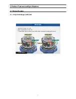
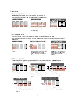
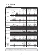
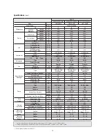
2. Product Features and Specifications

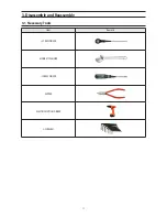
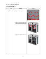
3. Disassembly and Reassembly

4. Troubleshooting

5. PCB Diagram and Parts List

6. Wiring Diagram

7. Cycle Diagram

8. Key Options

9. Trial Operation

CONTENTS

DVM CHILLER

DVM CHILLER

AG042KSVANH/AG056KSVANH/AG070KSVANH
AG042KSVGNH/AG056KSVGNH/AG070KSVGNH

SYSTEM AIR CONDITIONER

Summary of Contents for AG042KSVANH

Page 1: ...ssembly and Reassembly 4 Troubleshooting 5 PCB Diagram and Parts List 6 Wiring Diagram 7 Cycle Diagram 8 Key Options 9 Trial Operation CONTENTS DVM CHILLER DVMCHILLER AG042KSVANH AG056KSVANH AG070KSVANH AG042KSVGNH AG056KSVGNH AG070KSVGNH SYSTEMAIRCONDITIONER ...

Page 2: ...DVM CHILLER derived model status Application division Derived models Non built pump AG042KSVANH EU AG056KSVANH EU AG070KSVANH EU Built pump AG042KSVGNH EU AG056KSVGNH EU AG070KSVGNH EU ...

Page 3: ...ommunicationerrorbetweenhydroandoutdoorunitduringtracking 41 4 3 4 Communicationerrorbetweenindoorandoutdoorunitaftertracking 43 4 3 5 InternalcommunicationerroroftheoutdoorunitC Box 44 4 3 6 InternalPCBcommunicationerroroftheoutdoorunitC Box 45 4 3 7 Outdoortemperaturesensorerror 47 4 3 8 CONDOUTtemperaturesensorerror Open Short 48 4 3 9 OutdoorunitCONDOUTsensorbreakawayerror 49 4 3 10 Compressor...

Page 4: ... 4 3 48 HydrooutlettemperaturesensorBreakaway 93 4 3 49 Waterflowerror WaterpressuresensororFlowswitch 94 4 3 50 Erroronpumpmagneticswitchmalfunction 95 5 PCBDiagramandPartsList 96 5 1 ASSYPCBMAIN HYDRO 96 5 2 ASSYPCBMAIN 97 5 3 ASSYPCBSUB FAN 102 5 4 ASSYPCBSUB EMI PF 8Hpowermodelonly 104 5 5 ASSYPCBSUB EMI PF 9Hpowermodelonly 105 5 6 ASSYPCBMAIN HUB 107 5 7 ASSYPCBINVERTER 111 5 8 ASSYPCBSUB COM...

Page 5: ...lation is at least 2m away from electronic appliances such as TV video players and stereos This can cause irregular noise or degrade the picture quality O Please make sure the customer does not directly repair the product Arbitrary dismantling may result in electric shock or fire 1 3 Precautions for the Safety O Do not pull or touch the power plug or the subsidiary power switch with wet hands This...

Page 6: ...e moving within the regulated pressure 1 5 PrecautionsforWeldingworktheDVMCHILLERPipe O Dangerous or flammable objects around the pipe must be removed before the welding O If the refrigerant is kept inside the product or the pipe then remove the refrigerant prior to welding If the welding is carried out while the refrigerant is kept inside the welding cannot be properly performed This will also pr...

Page 7: ... BLDC Inverter Motor 14 160 Hz 3rd generationVapor Injection maximization of low temperature heating performance DSI System Inverter based 2 Product Features and Specifications 2 1 Product Features 2 1 1 Major Advantages of Product ...

Page 8: ... will Thermo Off Maximum capacity Maximum capacity Capacity control Minimum capacity 3 Efficiency priority control Control based Water Out Temp Uses the average value of the Water Out Sensor of the Unit whose pump inside the module is in operation Precision control while in low load state Load response speed prioritized when load capacity is increased k tG 㾔 k tG 㾔 Releasing efficient operation st...

Page 9: ...cebyhigheffectivenessapplyingplatetypeheatexchanger Refrigerant cooling system It is cooling technology of inverter circuit that use refrigerating cycle technology Cooling inverter circuit Efficientoperation capacity Manufacture hot cool water using plate type heat exchanger Freeze protection control specification application for shrinkage temperature pressure Air purge Drain valve In out flange P...

Page 10: ...ontrol contact Supply of Laod Sensor Control Box Inverter Main PCB Change Main PCB Separation of Load Control Deleting of option resistance by model standardization Need of option download at the time of the PCB replacement Hub PCB New Hub PCB Separation of Load Control Improvement of the fixed form of Load Sensor wire FAN PCB FAN Controller using 3 phase power Prevention of phase imbalance Protec...

Page 11: ...ontrol Box Inverter InverterPCB Compressor control PCB PF No 8 Inverter controller PF No 9 Inverter controller Communication terminal block Communication terminal block mounted on the PCB REACTOR Small capacity PF No 8 Large capacity PF No 9 Compressor 70cc high capacity compressor application ...

Page 12: ...ater inlet Air side Heat Exchanger Water Side Heat Exchanger WaterTemp sensor Water Pressure sensor Water outlet Water inlet Control Box Hydro Side Air side Heat Exchanger WaterTemp sensor Water Pressure sensor Water Side Heat Exchanger Water Pump Control Box Inverter Receiver Accumulator Compressor Oil separator Sub cooler Hydro control Inverter control Pump built in model only ...

Page 13: ...e DS GB070FAVA DS GB070FAVA DS GB070FAVA Oil Type PVE PVE PVE Refrigerant Type R410A R410A R410A Factory Charging kg 18 18 18 Fan Type Propeller Propeller Propeller Output x n W 630 x 2 630 x 2 630 x 2 Air Flow Rate CMM 364 182 x 2 364 182 x 2 392 196 x 2 Water Side Heat Exchanger Type Plate type heat exchanger Plate type heat exchanger Plate type heat exchanger Water Flow Cooling Heating LPM 120 ...

Page 14: ... Propeller Propeller Output x n W 630 2 630 2 630 2 Air Flow Rate CMM 364 182 2 364 182 2 392 196 2 Water Side Heat Exchanger Type Plate type heat exchanger Plate type heat exchanger Plate type heat exchanger Water Flow Cooling Heating LPM 120 160 186 200 Pressure Drop kPa 60 100 120 Max Operationg Pressure MPa 1 0 1 0 1 0 ConnectionType Flange Flange Flange Pipe Inlet Outlet A 40 40 50 Q Ty EA 2 ...

Page 15: ...11 3 1 Necessary Tools 3 Disassembly and Reassembly Item Remark SCREW DRIVER MONKEY SPANNER SCREW DRIVER NIPPER ELECTRIC MOTION DRIVER L WRENCH ...

Page 16: ...se Screw Driver 2 Remove the 8 screws and then separate the left side Cover Control Box of Hydro part and right side Cover Control Box of Inverter part Use Screw Driver 3 Remove the Power Compressor Valve Motor Sensor connector of Assy PCB 3 2 Disassembly and Reassembly 3 2 1 AG042 056 070KSV666 ...

Page 17: ...ock and Communication Terminal Block remove the 2 screws which is fixed to Terminal Block Cover 5 Remove the 4 screws which is fixed to Cabinet for Terminal Block protection and then remove the 2 screws from the Terminal Block 6 Remove the 5 screws from the front part ...

Page 18: ...he 12 screws from the outside of side refrigerant cooling part Do not separate Heat Sink pulling Assy Piping Cooling piping compulsorily It can be a cause of parts damage 8 Remove the 2 screws from the inside of side refrigerant cooling part ...

Page 19: ...e the 2 screws securing the coupling points Loosen BRACKET PHE SCREW where to hold the heat exchanger No code SPEC Q ty 1 6003 001053 M6 2 2 6009 001369 M4 4 3 General NUT M8 2 2 3 2 1 5 Pump part Pump built in model AG042 056 070 KSVGNH 13 Separates the pipe connected pump by separating 4 coupling fixed screws 14 Separates 3 bracket fixed screws fixed to base No Code SPEC Q ty 1 GENERAL NUT M8 4 ...

Page 20: ...cted to DVM CHILLER 5 Unscrews the fixed screw of CABINET FRONT 6 Separates wire of cycle parts connected to ASSY PHE from C BOX 7 Separate 2 bolts of coupling connected to ASSY PUMP 8 Unscrew 3 fixed screw of bracket fixed to Base 9 Unscrews a fixed screw fixing water pipe IN in front 10 Let down the coupling Rubber and pull out outwards Pump ASSY by raising slightly a back of Pump Bracket parts ...

Page 21: ...tween steel plate and nut must be 1 3 1 5mm when you assemble the cable holder Gap 1 4 0 1mm 16 Please reassemble in reverse order of disassembly Bolt torque at time of coupling tightening 200 10 kgfcm After reassembly please reassemble so that diagonal line part of coupling side is not intersected each other PROPERLY ASSEMBLED JOINT POSITIVE OFFSET WITH BOLT PAD CONTACT PROPERLY ASSEMBLED JOINT N...

Page 22: ...ew of CABINET FRONT and C BOX 3 Separate the connector from PBA 4 Separate Insu protecting the temperature sensor 5 Separate the temperature sensor by using spanner 6 Separate the temperature sensor It is applied Thermal Grease for an accurate temperature measurement Ŷ Cover the temperature sensor with Insu so that it is not affected from the outside Bolt torque 120 10 kgfcm ...

Page 23: ...nnected to inlet outlet of main water pipe 3 Drain all water of water pipe connected to DVM CHILLER 4 Unscrews the fixed screw of CABINET FRONT and C BOX 5 Separate the connector from PBA 6 Separate the pressure sensor by using spanner 7 Replace with the new pressure sensor Bolt torque 120 10 kgfcm ...

Page 24: ...e screw of inlet outlet water pipe flange connected to DVM CHILLER 5 Unscrews the fixed screw of CABINET FRONT 6 Separates wire of cycle parts connected to ASSY PHE from C BOX 7 Connect the refrigerant reclaimer in the charging port Recovering the refrigerant sealed in the product Use only charging port charging recovery of refrigerants 8 Separate the four points of the pipe connected to ASSY PHE ...

Page 25: ...w the screw of coupling connecting the two PHE in series 10 Separate 6 screws of Bracket fixing ASSY PHE 11 Please reassemble in reverse order of disassembly Bolt torque at time of coupling tightening 200 10 kgfcm ...

Page 26: ...ts A Binds a EEV Pressure sensor Temperature sensor Water temperature sensor by Cable Tie 6501 001110 L200 CableTie B Binds a High pressure switch Oil return valve by Cable Tie using Insu C Binds a High pressure sensor EVI Hot gas valve by Cable Tie using Insu CableTie HolderWire Etc ...

Page 27: ...t gas valve by Cable Tie using Insu 6501 001110 L200 CableTie E Binds a Low pressure sensor Temperature sensor bundle by Cable Tie F Binds aVapor injection valve High voltage switch Oil return valve High pressure sensor EVI Hot gas valve Low pressure sensor Temperature sensor by Holder wire 6501 001107 L368 CableTie G 4Way valve EVI EEV valve CableTie HolderWire Etc G D E F ...

Page 28: ...s a Communication wire Power wire Motor wire Suction temperature sensor by Holder wire DB61 00206A K Binds a Communication wire Power wire Motor wire Suction temperature sensor by Holder wire L Binds a Motor wire Power wire by Holder wire M Binds a Motor wire Power wire Communication wire Hydro part wire bundle by Holder wire N Binds a Hydro part wire bundle by Holder wire O COND OUT ACCUM OIL RET...

Page 29: ...Comp wire core to Bracket beam control box using large size Cable Tie 350mm Binds a Comp wire by Holder wire Remove the 3 screws and separate the connector and then separate the double layer structure of Control Box 1 No Code SPEC Q ty 1 6002 001149 M4 3 ...

Page 30: ...on Q ty 1 Comp Discharge 2 2 Comp Suction 2 3 Comp Vpaor Injection 2 4 Oil Sepa Out 4way 1 5 Oil Sepa Out Hot Gas 1 6 4Way Hot Gas 1 7 Sution Oil Return 2 8 Vapor Injection EVI Bypass 1 9 Accum 4Way 1 10 EEV Cond Out 2 11 Pinch Pipe 2 12 Subcooler Receicer Tube 1 All model s pipe welding position is same ...

Page 31: ...eWeldingPosition AG042 056 070KSV666 Series Frontweldingpart2 No Welding Position Q ty 1 Accum Oil Retrun valve Suction 1 2 4Way Assy Phe In 2 3 4Way Cond In 2 4 EEV Assy Phe Out 2 All model s pipe welding position is same ...

Page 32: ...ition Q ty 1 Discharge Oip sepa Tank 2 2 Suction Accum 1 3 Receiver Tank Receiver Tube 2 4 Receiver Tube Cooling 1 5 Cooling EEV 1 6 Accum EVI Bypass 1 7 EVI Bypass Subcooler 1 8 Subcooler EEV 1 9 Oil Sepa tank Oil Return 2 10 Oil Sepa tank Oil Sepa out 2 All model s pipe welding position is same ...

Page 33: ...isplay 17 InputwaterinTemperaturesensor 7 WarningDisplay 18 InputwateroutTemperaturesensor 8 DefrosteroperationDisplay 19 InputPHEOUTPressuresensor 9 Pump Compressor operationDisplay 20 InputPHEINPressuresensor 10 Pumpoperation 21 Pumpinterlock Controlperation Mode heatstorageoperation Control 11 FreezeprotectionDisplay 22 Quietfunction DemandfunctionForced fanfunction Unusualconditionreset Waterl...

Page 34: ... collection 9times Inverter compressor 1 check 10times Inverter compressor 2 check 11times Fan 1 check 12times Fan 2 check 13times End KEY operation To use key operating function for service and maintenance when installing module group set as main control or cancel in module group Body control settings Hydro control Dip S W 1 times On Modules How to ungroup Modular Controller Installation Manual R...

Page 35: ...e 60minutes Etc During the filling operation does not enter the special operation such as oil recovery defrost VacuumOperation OperationtofacilitatevacuumtoopenthevalveaftertheOutdoorUnitrepair Discharge mode Operation Block the Inverter PCB 3 phase relay after connected the power and through compressor DC voltage is discharging Discharge Mode Operation Process Push K2 button 6 times shortly INV1 ...

Page 36: ...start Defrost start It is after 10 minutes which Safety Start finishes Defrost off General defrost operation conditions are the same as Etc Defrost shut down and stop the normal pattern of the outdoor unit stop Method of Entry K2Tact Switch 8 times Start pattern Outdoor temperature is more than 10 C Cooling AutoTrial Operation Outdoor temperature is less than or equal to 10 C Heating AutoTrial Ope...

Page 37: ...r OK I converter NG Cable 20PIN download cable Method of PCB SW update and method of EEPROM download Outdoor EEPROM writing Tool Procedure PC SW S net pro 2 Refer to the S net pro 2 manual for more detailed information 1 Power on the system 2 Connect F1 F2 to converter 3 Connect Converter to PC 4 S Net pro 2 Connect Add on Outdoor EEPROM write This work only when communication is normal Converter ...

Page 38: ...or that occurred in outdoor unit and other methods of error display Error Number ĺ Outdoor unit address ĺ Error Number repeat display E471 ĺ U200 ĺ E471 ĺ U200 E206 ĺ C001 ĺ E206 ĺ C002 DISPLAY Explanation When displaying Error 101 700 When E206 occurs Displays address of subordinate within the set C001 HUB C002 FAN C003 INV1 C004 INV2 When displaying outdoor unit address Ex U200 Outdoor unit 1 U2...

Page 39: ...b MICOM of inverter controller 205 Communication error of inverter controller main PBA sub PBA Sub PBA communication all not received 206 Communication error of inverter controller main PBA sub PBA S PBA communication partially not received Specification of PBA display for actual communication error C001 Hub PCB communication error C002 Fan PCB communication error C003 INV1 communication error C00...

Page 40: ...t sensor error 396 Fan2 DC Link voltage sensor error 399 Heat sink temperature sensor error of Fan2 400 INV2 IPM OverHeat error 407 COMP down due to high pressure 410 COMP down due to low pressure 416 COMP down due to discharge temperature 425 Phase reversal or phase failure 428 COMP down due to compressor not controlled 438 EVI EEV open error 439 Error due to refrigerant leakage Examine when syst...

Page 41: ...ror 560 Switch option setting error 901 Hydro inlet temperature sensor Tw1 Short Open 902 Hydro outlet temperature sensor Tw2 Short Open 907 Frozen damage error 908 Error when freeze prevention Comp Off 3 times 909 Error when freeze prevention Comp Off 3 times 910 Error on hydro outlet temperature Tw2 sensor Detached 911 Water Flow error Water pressure sensor 913 Flow Pressure sensor error E911 oc...

Page 42: ...ase 2 If there is any terminal without normal voltage then check the power outside the air conditioner and take the appropriate measures 3 If the 3 phase voltage is normal then use the 3 phase tester to display the phase of the power cable Change the power cable connection if reversed phase is displayed 4 Take the above measures press the reset key K3 and then check the power once more 5 Check the...

Page 43: ... a f G1 G2 b c e d SEG4 Display of inverter control part Step Display content Display SEG1 SEG2 SEG3 SEG4 At initial power input Checking segment display 8 8 8 8 Chiller units Communicating Setting Addressing Number of connected Chiller units SEG1 SEG2 SEG3 4 SEG3 4 A d 0 1 After communication setting usual occasion Transmit Reception address Hydro control A Hydro control 0 0 0 䭓 Displays if commu...

Page 44: ...bPCBdefective 4 Highpressureswitchoperation 1 InspectionMethod ReplaceMainPCB ChecktheconnectionstatusofEMIPCB ChecktheshortcircuitofEMIPCBFuse Refrigerantovercharge Highpressureswitchisdefective No No Yes Yes Yes HUBPCBCN70AC220Visconnected Isahighpressureswitchnormal ChecktheshortcircuitofHubPCB ReplaceHubPCB No Yes ConfirmablinkingofHubPCBLED Connectingthecommunicationwire CN96 No Yes Didyouche...

Page 45: ...outdoorunit Removethecommunicationcablewhichconnectsthe hydrototheoutdoorunit andmeasurethe2wiresof theoutdoorunitsidewithascope Checkthecommunicationcablewhichconnectsthe hydrototheoutdoorunit Ifthereisnopeculiarity replacetheHydroPCB Isthevoltagebetweenthe2cablesasquarewavewith DC 0 7Vormore Istherenosignof thehydroresponseonthedisplay duringtracking Checkthecommunicationcableandthen replacetheH...

Page 46: ...ntrol part 1 2 2 Measure the resistance of the communication IC Ɣ Measurement Method Measure No5 No6 Pin resistance Measure No5 No7 Pin resistance Display IC No 1 pin No 5 No 6 No 7 3 Normal and defective judgment is tested for communication IC by using measured resistance Ɣ Judgment as normal Each resistance value should be measured in tens of kΩ to hundreds of kΩ Difference between both resistan...

Page 47: ...e with a scope Check the communication cable which connects the hydro to the outdoor unit If there is no peculiarity replace the Hydro PCB Check the communication cable and then replace the Hydro PCB Check the communication cable and the connector of the outdoor unit PCB side and replace the PCB 0 7V 0 7V Good Defective If there is no peculiarity in the address check the communication cable and re...

Page 48: ...onnector breakawayfromthePCB RestartoperationaftercheckingtheInverter PCB2CN31andPCB2CN32Communication wire Connector 3 4PinShort ServiceafterturnofftheMainPower No Yes Yes IsInverterPCB1CN32andInverterPCB CN31connectoraccuratelyconnected 1 ChecktheInverterPCB1CN32 CN91andFan PCBCN12Communicationwire Connector 2 RestartoperationafterconnectingtheHubPCB CN97andFanPCBCN13connector Serviceafterturnof...

Page 49: ...Box internal Inverter PCB Fan PCB Hub PCB defective 1 Inspection Method ReplaceHubPCB ReplaceFanPCB FanPCBTXpart Breakage ReplaceConnectionwire Checktheconnectionstatus CN12connector FanPCBCN13connection No No No Yes Yes Yes Connectionwireof HubPCB MainPCBdidconfirmation Verifythebrokenwire LightingofFanPCBLD41didconfirmation IsFanPCBCN13connectoraccuratelyconnected E206C001 E206C002 ...

Page 50: ...oroftheoutdoorunitC Box cont ReplaceINVPCB INVPCBTXpart Breakage Checktheconnectionstatus CN91connector CN32connectorconnection No No Yes Yes LightingofINVPCBLD11didconfirmation IsINVPCBCN32connectoraccuratelyconnected E206C003 C004 ...

Page 51: ...istance valuesignificantlystrayfromthefollowing temperaturetable Afterseparatingtheoutdoortemperature sensorconnectorfromthePCB measure theresistancevaluebetweentheterminals RestartoperationafterreplacethePCB Restartoperationafterconnecting theconnectortothePCB Replacethissinceitisthedefectiveof theoutdoortemperaturesensoritself Yes No No Yes Temperature C 70 60 50 40 30 20 10 0 10 Resistance KΩ 2...

Page 52: ...heresistance valuesignificantlystrayfromthefollowing temperaturetable AfterseparatingtheoutdoorCondOutsensor connectorfromthePCB measurethe resistancevaluebetweenthetwoterminals RestartoperationafterreplacethePCB Restartoperationafterconnecting theconnectortothePCB Replacethispartasitisthedefectiveofthe outdoorCondOutsensoritself Yes No No Temperature C 70 60 50 40 30 20 10 0 10 Resistance KΩ 2 2 ...

Page 53: ...f cm OK Lowpressureaverage 8 5kgf cm OK Teva out Tair in 3 C OK Teva in Tair in 2 C OK Tcond out Tair out 0 C NO Everycompressorisinoperation indoorunitoperationandThermoOn OK ErrorContent OutdoorCondOutsensorbreakawayerror 2 Causeofproblem Yes Yes IstheCondOut sensorandthesensorholdercorrectly attached Arethereanychanges inthevalueofthesensorwhenoperatingfrom stoptoheating IstheCondOutsensor resi...

Page 54: ...ayfromthePCB Didtheresistance valuesignificantlystrayfromthefollowing temperaturetable AfterseparatingtheCompressorDischargeor TopTemperaturesensorconnectorfromthePCB measuretheresistancevaluebetween thetwoterminals RestartoperationafterreplacethePCB Restartoperationafterconnecting theconnectortoPCB Replacethispartasitisthedefectiveof theCompressorDischargeor TopTemperaturesensoritself Yes No No T...

Page 55: ...emperature 10 3 RelevantdischargeorToptemperature Highpressuresaturationtemperature 4 Incaseofkeep30minutesinstatethatsatisfyallaboveconditions 1 2 3 Causeofproblem CompressordischargeorToptemperaturesensorbreakawayanddefective startingbadnessofcompressor Complete Re insertsensorRe attachsensorholder No Yes IstheDischargeorToptemperaturesensorandthe sensorholdercorrectlyattached Defectivesensor Re...

Page 56: ...suctiontemperaturethatisonpresentoperation Iflessthan2 for30minutestokeep Judgmentatheatingoperationonly Causeofproblem Suctiontemperaturesensorbreakaway defective Complete Is Suction sensor and sensor Holder accurately attached Is Suction sensor resistance value reasonable Refer to E231 DefectiveSensor ReplaceSensor No Re insertthesensor Re attachthesensorholder No Yes Yes ...

Page 57: ...stopped 2 AnOpen Shorterrorwilloccuriftheinputvoltagestandardrangeof0 5V 4 95Visexceeded 2 InspectionMethod ReplaceHighPressuresensor Pleasere inspectafterconnecting theconnectortothePCB No Yes DidtheHighPressure sensorconnectorgetdisconnected fromthePCB Refillrefrigerantaftervacuum No Yes Isthererefrigerantinsidetheset Pleasecheckbyconnectingthemenufoldergauge totheservicevalve ReplacePCB No Yes ...

Page 58: ...stopped 2 AnOpen Shorterrorwilloccuriftheinputvoltagestandardrangeof0 5V 4 95Visexceeded 2 InspectionMethod Replace LowPressuresensor Pleasere inspectafterconnecting theconnectortothePCB No Yes DidtheLowPressuresensorconnector getdisconnectedfromthePCB Refillrefrigerantaftervacuum No Yes Isthererefrigerantinsidetheset Pleasecheckbyconnectingthemenu foldergaugetotheservicevalve ReplacePCB No Yes Ou...

Page 59: ... 5 8 8 3 12 1 18 0 27 3 43 0 Resistancevaluemeasurepart SUCT SUCT No No Yes Yes Didtheconnectorfor theOutdoorSuctionsensorbreakaway fromthePCB Didtheresistance valuesignificantlystrayfromthefollowing temperaturetable SeparatetheconnectoroftheOutdoorSuction sensorfromthePCBandmeasuretheresistance valuebetweenthe2terminals RestartoperationafterreplacethePCB Restartoperationafterconnecting theconnect...

Page 60: ...8 3 12 1 18 0 27 3 43 0 Resistancevaluemeasurepart LIQUID LIQUID Yes Yes Didtheconnectorfor theLiquidPipeTemperaturesensorbreakaway fromthePCB SeparatetheconnectoroftheLiquidPipe TemperaturesensorfromthePCBandmeasure theresistancevaluebetweenthe2terminals Didtheresistance valuesignificantlystrayfromthefollowing temperaturetable RestartoperationafterreplacethePCB Replacethispartasitisthedefectiveof...

Page 61: ...ncevalue significantlystrayfromthefollowing temperaturetable SeparatetheconnectoroftheOutdoorEVIIn TemperaturesensorfromthePCBandmeasure theresistancevaluebetweenthe2terminals RestartoperationafterreplacethePCB Restartoperationafterconnecting theconnectortoPCB Replacethispartasitisthedefectiveofthe OutdoorEVIInTemperaturesensoritself No No Yes Yes Temperature C 70 60 50 40 30 20 10 0 10 Resistance...

Page 62: ...cevalue significantlystrayfromthefollowing temperaturetable SeparatetheconnectoroftheOutdoorEVIOut TemperaturesensorfromthePCBandmeasurethe resistancevaluebetweenthe2terminals RestartoperationafterreplacethePCB Restartoperationafterconnecting theconnectortoPCB Replacethispartasitisthedefectiveofthe OutdoorEVIOutTemperaturesensoritself No No Yes Yes Temperature C 70 60 50 40 30 20 10 0 10 Resistanc...

Page 63: ...stance value significantly stray from the following temperature table Separate the connector of the Suction 2 sensor from the PCB and measure the resistance value between the two terminals Restart operation after changing PCB Restart operation after connecting the connector to PCB Change this part as it is the fault of the outdoor Suction 2 sensor itself Yes No No Temperature C 70 60 50 40 30 20 1...

Page 64: ...nconnected error 1 Check the FAN motor and PBA connection 2 When connected Inverterr checker if LED operates in the normality External factors or when LED operates by abnor mality replace the FAN PBA E367 COMP 2 wire unconnected error 1 Check the Compressor and Inverter PBA connection 2 When connected inverter checker if LED operates in the normality External factors or when LED operates by abnor ...

Page 65: ...high pressure sensor Check the relevant EEV Check the piping Check the refrigerant amount Replace relevant parts motor or fan Connect S net and Manifold Gauge Essential requirement 1 Inspection Method Inverter Hydrocontrolpartdisplay JudgmentMethod Value of the high pressure sensor is detected at 40kgf cm or more Causeofproblem Coolingoperation Outdoorunitfanmotorproblem constrained defective Moto...

Page 66: ...Corlessforheatingandoperatingoutsidetemperatureat 15 CorlessforCooling 예 예 예 아니오 예 아니오 아니오 예 아니오 Is the S net estimated value and the Manifold Gauge value in range Are the indoor unit and outdoor unit EEV normally operating Are there any blockage inside the pipe filter etc Check the refrigerant amount Is there any leakage in the liquid pipe valve or the discharge check valve of the not go end outd...

Page 67: ...emperaturesensordefective Blockedpipeanddefective Leakageofcompressordischargecheckvalveofnot go endoutdoorunit No No No Yes Yes Replace compressor discharge temperature sensor TOP temperature sensor Check the relevant EEV Check the piping Connect S net and Manifold Gauge Essential requirement Yes No Is the resistance value normal for the compressor discharge temperature sensor TOP temperature sen...

Page 68: ...rcuit ReplaceInverterPCB PowerOff Yes Yes No Yes DidtheMain TerminalBlockandPowerR S T Nis connectedproperly PowerBOXTerminal Checkthephase to phase connection380VoftheR S Tandthenrestart N phasemustbeproperlyconnected No No No Yes Reactorterminalconnectionandthenrestartit Lowvoltageerrorduringthisinitialcharge ReplaceFuse iftherectifierdiode oftheinverterPCBisnormal Refertomeasuringmethodusingate...

Page 69: ...ormore Causeofproblem IndoorandoutdoorEEVbreakdown 4Wayvalvebreakdown Highandlowpressuresensordefective Refrigerantshortage Yes Arethe4WayValvenormallyoperating AretheIndoorUnit andOutdoorUnitEEVnormally operating Iscurrentofcompressornormally Complete TrialOperation Replacedefectivesensor Checkthe4WayValve ChecktherelevantEEV Checkthecompressor Checktherefrigerantamount Yes Yes No IstheS net esti...

Page 70: ...l IsEEVcoilaccuratelyinstalled Yes Breakdown ReplaceIntercooler ChecktheIntercoolerleakage Normal Breakdown ReplaceEVIEEV ChecktheEVIEEVleakage Normal Inverter Hydrocontrolpartdisplay JudgmentMethod DSH 10 C EVI Out in 0 C frequency 65Hz 40 minutes maintaining Causeofproblem EVIEEVandintercoolerleakage excessiverefrigerantamount outdoorcheckvalveinsertedopposite ...

Page 71: ...m No Yes Isthererefrigerantinsidetheset Pleasecheckbyconnectingthemenu foldergaugetotheservicevalve ReplacePCB No Yes OutofthePCBPressure sensorterminals istherevoltagebetween pins3and45V The ź mark is the 1st pin on the PCB Outdoorunit display Refrigerantleakagejudgmentbeforestarting Whenstart refrigerantleakagejudgment Judgment Method Beforestarting Beforecompressorstartingaftersystemhalt2minute...

Page 72: ...to outdoor temperature Inverter Hydrocontrolpartdisplay Preventionofcoolingoperationduetolowtemperatureofoutdoor JudgmentMethod Coolingoperation Whentheoutdoortemperatureislessthan 25 C Causeofproblem Systemprotectionoperationstatus Isnotbreakdown ...

Page 73: ...Compressorconnectionerror DefectiveCompressor DefectivePCB PowerOffandthenRestart ReplaceFanPCB Yes Istheresistance valuebetweendifferentphasesof anMotor UļV VļW WļU lessthan10Ω ReplaceFanMotor No Yes Istheresistancebetweenthebodyof FanMotorandchassisMΩ ReplaceFanMotor No Yes DoestheCompressorconnection wireproperlyconnect Checktheconnectionwire No 1 InspectionMethod ...

Page 74: ...onMethod 1 RefertoFigure1andTable1 respectivelytheresistancevalueanddiodevoltagevaluemeasure 2 AccordingtothecriterioninTable1todeterminewhetherthefailureofIPM Division MeasuredPoint Criterion Remark Measure theresistancevalues 40 U Morethan30 Measurementerrorcanoccurforreasonssuchastheinitial measurementcondenserdischarge Measuredoveratleastthreetimes 40 V 40 W U 34 V 34 W 34 Measurethediode volt...

Page 75: ...Method PowerOnandthentrialoperation PowerOff ReplaceFanPCB Yes Didtheerroroccurs EndofService No Yes Didyoucheck theforeignobjectsontheFan rotarywing Removetheforeignobjectsandrestart No Yes Fandorotatebyhand ReplaceFanMotor No No Ifyourotatethefanbyhand thenoiseoccurs ReplaceFanMotor Yes Yes Connectionwireof FanMotordidconfirmation Checktheconnectionstatusof theFan1andFan2 Checktheconnectionstatu...

Page 76: ...e Hub PCB or Main Hub connection wire Inverter Hydrocontrolpartdisplay Preventionofheatingoperationduetohightemperatureofoutdoor JudgmentMethod Momentarystopofcompressorduetomomentaryblackout Causeofproblem Momentarystopofcompressorduetomomentaryblackout ...

Page 77: ...fectiveconnectionwire DefectiveFanMotor DefectivePCB Defectiveinstallationconditions 1 InspectionMethod PowerOff PowerRestart ReplaceFanMotor Yes Didtheerroroccurs EndofService No Yes Connectionwireof FanMotordidconfirmation Verifythatthewirefolded ortheconnectionis detached Checktheconnectingwireandrestartit No Yes Isthereanythingstrangein appearanceFanMotor ReplaceFanPCB No ...

Page 78: ...Massemblydefective Defectiveheatsinkcooling 1 InspectionMethod PowerOff Yes Didchecktheforeignobjects betweentheheatsinkpin Removeforeignobjects Coldheatsinkassemblydefectoccurs No Yes Istheboltoftheheatsinkfullytightened TightenBolt No Yes Didchecktheforeignobjects betweentheheatsinkandIPM No Complete Removeforeignobjectsand applytheheatsinkgrease Andthenreassembly ...

Page 79: ...thod PowerOffandthenRestart Continue Yes IsHotGasBypassValvestartup theinitialpowerisapplied HubReplacePCB No Yes HotGasBypassValveinitial startupdoesitwork ReplaceHotGasBypassValve No Yes Istheresistance valuebetweendifferentphasesof compressor UļV VļW WļU lessthan2Ω ReplaceCompressor No Yes Istheresistance betweenthebodyofCompressorand chassisMΩ ReplaceCompressor No Yes DoestheCompressor connect...

Page 80: ... ReplaceNo 1InverterPCB ErrorofNo 2Compressor ErrorofNo 2Compressor ReplaceNo 2Compressor ErrorofNo 2Compressor ErrorofNo 1Compressor ReplaceNo 2InverterPCB Continue Yes Didtheerroroccurs No Beforechange Afterchange Error dependingonthesituationreplacethe CompressororPCB Restart Inverter1 Compressor2 Inverter2 Compressor1tothewiringchange PowerOff PowerOffandthenRestart EndofService ...

Page 81: ...utdoorunitinstalledproperly Removetheobstaclesandcheck thestatusoftheinstallation No Yes Istemperature sensorlocationandthemeasurement valuenormally PowerOff andthenreplacement orcorrectionofthesensorlocation No Yes Istheresistancevalue betweenphaseofCompressorwire U V V W W U lessthan2Ω ReplaceCompressor No Yes Istheresistancebetween thebodyofCompressorand chassisMΩ ReplaceCompressor No Yes Doest...

Page 82: ...ErrorofNo 2Compressor ReplaceNo 1InverterPCB ErrorofNo 2Compressor ErrorofNo 2Compressor ReplaceNo 2Compressor ErrorofNo 2Compressor ErrorofNo 1Compressor ReplaceNo 2InverterPCB Continue Beforechange Afterchange Error dependingonthesituationreplace theCompressororPCB Restart Inverter1 Compressor2 Inverter2 Compressor1tothewiringchange PowerOff ...

Page 83: ...ionMethod 1 RefertoFigure1andTable1 respectivelytheresistancevalueanddiodevoltagevaluemeasure 2 AccordingtothecriterioninTable1todeterminewhetherthefailureofIPM Division MeasuredPoint Criterion Remark Measure theresistancevalues P IGBT U Morethan30 Measurementerrorcanoccurforreasonssuchastheinitial measurementcondenserdischarge Measuredoveratleastthreetimes P IGBT V P IGBT W U N IGBT V N IGBT W N ...

Page 84: ...on No Yes Is Power connection accurately conected Power Off Check the connector connection No Yes Is EMI PCB R S T Wire and Terminal block connector accurately connected Replace Fuse or EMI PCB No Yes Did the Fuse is open No Yes Is Reactor accurately connected Check the Reactor connection No Yes Is Inverter PCB R S T Wire and EMI PCB CN21 connector accurately connected Power Off and then re connec...

Page 85: ...the voltage value is more than 4 8V or less than 0 2V Cause of problem DC Link Connector disconnected PCB voltage sensing circuit defective Check the connector connection Check the status of DC LINK Connector Power Off Replace FAN PCB E496 E469 Replace No1 INVERTER PCB E369 Replace No2 INVERTER PCB 1 InspectionMethod DC power wire Inv PCB DC power wire Fan PCB ...

Page 86: ...pectionMethod Replace Fan PCB Yes Replace Outdoor Fan Motor No Yes Istheresistancevalue betweendifferentphasesofFanMotor UĺV VĺW WĺU lessthan10Ω Replace Outdoor Fan Motor Reconnect wires Housing Connector No No Yes Yes Is the resistance between the body of Fan Motor and chassis MΩ Is the Fan Motor wire properly connected to FAN PCB Power Off Fan PCB wire connection FAN Motor Connector Hall sensor ...

Page 87: ...r unit display FAN PCB FAN1 FAN PCB FAN2 Judgment Method Occurs when overcurrent flows in the IPM Detected by H W or S W Cause of problem Defective FAN Motor 1 InspectionMethod Yes Power Off E489 Replace No1 Fan motor E389 Replace No2 Fan motor ...

Page 88: ... Current sensor OUTDOOR FAN PCB FAN2 Output Current sensor Judgment Method Sensor Output detection Judged as an error if the detected value is More than 4 5V or less than 0 5V Cause of problem Input voltage defective PCB voltage sensing circuit defective Power Off Replace Inverter PCB Replace Fan PCB Yes No Is Power connection accurately connected E485 or E385 E468 or E368 E493 or E393 Power Cable...

Page 89: ... JudgmentMethod N phasewiringerrorandEMIFuseshort DC LinkOvervoltage Lowvoltageoccurs Causeofproblem Checktheinputwiring EMIFuseshort 1 InspectionMethod PowerOff Yes IsInverterPCBCN15 andFanPCBCN11DC Linkvoltageconnection wireaccuratelyconnected Connectionandthenrestartit No ReplaceFanPCB ...

Page 90: ...anufacturing FanMotordefective 1 InspectionMethod Replace Fan PCB Restart Whentheerrorisrepeated replacetheFanMotor End of Service No Yes Yes Did the error occurs Check the connecting wire and restart it No Yes Connectionwire ofHALLICdidconfirmation Verifythatthewirefolded ortheconnection isdetached Check the connecting wire and restart it No Yes HALL IC on the PCB is connected correctly Power Off...

Page 91: ...2000 1 47 60 1600 1 29 70 1200 1 07 80 750 0 76 90 650 0 68 Temperature C NTC ohm AD V 100 500 0 55 105 450 0 51 110 380 0 44 120 300 0 35 130 250 0 30 140 200 0 25 Complete Yes Yes Yes Applytheheatsinkgreaseandthenreassembly No Didproperlyapplytheheatsinkgrease BetweentheheatsinkandtheIPM Yes TightenBolt Screw Removeforeignobjectsandapplytheheatsink grease Andthenreassembly No No Istheboltofthehe...

Page 92: ...option use of other model or set of the relevant outdoor unit compressor breakdown DownloadrelevantmodelEEPROMandthenreset Setthecompressorbreakdownsettingvalueas notset Whensettingbreakdownforrepairandreplaceof compressor Changethesettingafterreplace No Yes IstheCompressorbreakdown settingvalueis notset ConnectoutdoorunitEEPROMandthenreset No Yes IstheoutdoorunitEEPROMaccuratelyconnectedto connec...

Page 93: ...breakaway fromthePCB Didtheresistancevalue significantlystrayfromthefollowing temperaturetable Inverter Hydro control part display Judgment Method Refer to the inspection method below Cause of problem Hydro Unit Water In Temperature Sensor Open Short error Afterseparate theHydroinlettemperaturesensorconnector fromPCB measuretheresistancevalueof betweenbothterminal Resistancevalue measurepart Tempe...

Page 94: ...thispartasitisthedefectiveof HydroInTemperatureSensoritself RestartoperationafterreplacethePCB No No Yes Yes DidtheconnectorforWaterOutTemperature SensorbreakawayfromthePCB Didtheresistancevalue significantlystrayfromthefollowingtemperature table SeparatetheconnectorofHydrounitinletwater TemperatureSensorconnectorfromthePCBand measuretheresistancevalue betweenthe2terminals Temperature Resistance K...

Page 95: ...er flow Check the Hydro outlet temperature of circulation water Check the piping system of circulation water Pump Strainer Valves Check the defect of hydro outlet temperature sensor Make sure the Hydro inlet water temperature is lowered Does circulation water flow maintain at least the recommended flow Is Water Out temperature more than 3 Check the EVA In Out temperature Is EVA In Out temperature ...

Page 96: ...spection Method No No No Yes Yes Check the circulation water flow Check the Water Out temperature of circulation water Check the piping system of circulation water Pump Strainer Valves Check the defect of hydro outlet temperature sensor Make sure the Hydro inlet water temperature is lowered Does circulation water flow maintain at least the recommended flow Is Water Out temperature more than 3 Is E...

Page 97: ...re sensor Completef Check the operate abnormally of Outdoor Unit Check the refrigerant clogging EEV Sensor defective Replace sensor Reconnect the sensor and reinstall the sensor holder Is Hydro Out temperature sensor and sensor holder accurately mounting Is Hydro Out temperature sensor resistance value normal Refer to the table of resistance value Among the Indoor Unit operation is temperature cha...

Page 98: ... detect the signal of Flow sensor Flow shortage of Water piping system 1 Inspection Method No No Yes Yes Check the connection status of Flow sensor Connect the Flow sensor and then restart it Check the piping system of circulation water Pump operation Strainer clogging Hydro control part Are Flow sensor is connected to the PBA Measurement of water flow Does circulation water flow maintain at least...

Page 99: ...blem PumpMagneticSwitchMalfunction Pump interlock input contact connection status During pump operation the On signal to the contact does not enter in a row during the pump interlock delay time error occurs Pump interlock delay time Setting options see Hydro 1 3 5 7 9 11 13 15 17 19 2 4 6 8 10 12 14 16 18 20 B T B Pump interlock contact input ...

Page 100: ...96 1 2 3 4 5 6 7 8 9 10 12 11 13 14 15 5 PCB Diagram and Parts List 5 1 ASSY PCB MAIN HYDRO Model All models name is commonness ...

Page 101: ...OMP_OP_DP SIGNAL 1 GND 2 3 5V 4 EEPROM_SELECT 5 EEPROM_SO 6 EEPROM_SI 7 EEPROM_CLK 1 EVA1_IN_TEMP 2 GND 3 EVA1_OUT_TEMP 4 GND 5 EVA2_IN_TEMP 6 GND 7 EVA2_OUT_TEMP 8 GND 1 PUMP_OP SIGNAL 2 3 PUMP_OP SIGNAL 1 12V 2 COM2_PCTRL_MICOM 3 COM2_VCHECK_A 4 COM2_VCHECK_B 5 COM2_MICOM_AD 6 5V 7 COM2_ENABLE 8 COM2_F3 9 COM2_F4 10 COM2_Tx 11 COM2_Rx 12 GND 1 FREEZE_PROTECTION_DP SIGNAL 2 3 FREEZE_PROTECTION_DP...

Page 102: ...98 1 2 3 4 5 6 8 9 10 11 13 12 14 7 ASSY PCB MAIN HYDRO cont Model All models name is commonness ...

Page 103: ...ORAGE_OP SIGNAL 10 GND 11 THERMAL_STORAGE_CTRL SIGNAL 12 GND 13 THERMAL_STORAGE_ THERMO SIGNAL 14 GND 1 WATER_OUT1 TEMP 2 GND 1 WATER_IN TEMP 2 GND 1 WATER_OUT2 TEMP 2 GND 1 EEV1_B_bar SIGNAL 2 EEV1_A_bar SIGNAL 3 EEV1_B SIGNAL 4 EEV1_A SIGNAL 5 12V 6 12V 1 EEV2_B_bar SIGNAL 2 EEV2_A_bar SIGNAL 3 EEV2_B SIGNAL 4 EEV2_A SIGNAL 5 12V 6 12V 1 COM3_OF1 2 COM3_OF2 3 12V 4 GND 5 COM2_F3 6 COM2_F4 1 OUTD...

Page 104: ...100 3 2 1 5 4 6 7 8 9 10 11 12 13 14 15 16 5 2 ASSY PCB MAIN Model All models name is commonness ...

Page 105: ...3 DRED3 SIGNAL 4 GND 5 5V 1 12V 2 ERROR_CHECK_OUT SIGNAL 3 12V 4 COMP_CHECK_OUT SIGNAL 1 KEY_IN_3 SIGNAL 2 GRID_8 SIGNAL 3 KEY_IN_4 SIGNAL 1 EXTERNAL_CONTROL SIGNAL 2 GND 1 GAS_LEAK SIGNAL 2 GND 1 COM_C 2 COM_D 3 4 12V 5 GND 1 COM_A 2 COM_B 3 5V 4 GND 1 COM_E 2 COM_F 1 COM_A 2 COM_B 1 5V 2 GND 1 12V 2 GND 1 PUMP_DOWN_START SIGNAL 2 12V 3 PUMP_DOWN_END SIGNAL 4 12V CN43 INV COMM CN901 DRED CN88 GAS...

Page 106: ...102 1 2 3 4 5 6 7 8 9 10 11 12 13 14 15 5 3 ASSY PCB SUB FAN Model All models name is commonness ...

Page 107: ...D 3 4 GND 5 6 12V 7 COMM SIGNAL 8 COMM_OUT SIGNAL 9 AGND 1 P_DC 2 GND 1 12V 2 COMM SIGNAL 3 COMM_IN SIGNAL 4 AGND 1 RXD_DEBUG2 2 TXD_DEBUG2 3 BOOT2 4 TDO2 5 TCK2 6 TDI2 7 TMS2 8 9 GND 10 5V 11 12 13 14 15 16 17 18 19 20 1 U 1 V 1 W 1 5V 2 VIEWER1_DAC2 3 VIEWER2_DAC2 4 VIEWER3_DAC2 5 DATA_DAC2 6 CS_DAC2 7 CLK_DAC2 8 GND CN202 DOWNLOAD1 W1 FAN1 W CN401 POWER V2 FAN2 V CN201 DAC1 CN102 FAN1 HALL SENS...

Page 108: ...104 5 4 ASSY PCB SUB EMI PF 8 H power model only Model AG042 056KSV666 Series CN23 INVERTER220V CN21 FANA CN22 MAIN220 RST RSTINPUT 1 AC 2 3 AC 1 R 2 S 3 T 1 AC 2 AC T IN S IN R IN 1 3 2 4 ...

Page 109: ...105 1 2 4 3 5 6 7 8 9 10 11 5 5 ASSY PCB SUB EMI PF 9 H power model only cont Model AG070KSV666 Series ...

Page 110: ... 2 3 ACNEUTRAL 4 5 ACNEUTRAL 1 ACLIVE 2 3 ACNEUTRAL 1 EARTH PE 1 R OUT CN106 SOUT CN107 TOUT CN41 EARTH CN101 RIN 1 S OUT 1 T OUT 1 EARTH PE 1 R IN CN102 SIN CN103 TIN CN104 NIN 1 S IN 1 T IN 1 N IN ASSY PCB SUB EMI PF 9 H power model only cont Model AG070KSV666 Series ...

Page 111: ...107 5 6 ASSY PCB MAIN HUB Model All models name is commonness DC 1 2 3 4 5 6 7 8 9 10 11 12 ...

Page 112: ...CN45 TEMP SENSOR CN46 SUCT CN44 TEMP SENSOR CN906 SNOW SENSOR 1 LIQUID 2 LIQUID 3 COMP2 DISCHARGE 4 COMP2 DISCHARGE 5 COMP2TOP 6 COMP2TOP 1 SUCTION 2 2 SUCTION 2 3 HEX2 TOTAL SUCTION 4 HEX2 TOTAL SUCTION 5 6 GND 1 SUCTION 1 2 SUCTION 1 3 EVI INLET 4 ENI INLET 5 ENI OUT 6 EVI OUT 1 12V 3 GND 4 SNOW_SENSOR 5 PSD_POWER CN42 HIGHPRESSURESENSOR CN41 LOWPRESSURESENSOR CN97 INVCOMM CN96 MAIN HUBCOMM 1 HI...

Page 113: ...109 ASSY PCB MAIN HUB cont Model All models name is commonness AC 1 1 2 3 4 5 6 7 8 9 10 11 ...

Page 114: ...5 HOTGAS BYPASS2 CN703 EVI BYPASS CN716 OD EEV VALVE CN711 OIL RETURN VALVE 1 HOTGASBYPASS2 OILBYPASSVAVLE2 2 HOTGASBYPASS2 OILBYPASSVAVLE2 1 EVIBYPASS1 2 EVIBYPASS1 1 ODEEVVALVE OILBYPASSVAVLE1 2 ODEEVVALVE OILBYPASSVAVLE1 1 ACCUMOILRETURNVALVE 2 ACCUMOILRETURNVALVE CN708 4 WAY VALVE CN70 ACPOWERINPUT CN701EVIVALVE1 2 1 4 WAYVALVE 2 4 WAYVALVE 1 ACLIVE 2 ACNEUTRAL 1 EVIVALVE1 3 EVIVALVE2 7 EVIVAL...

Page 115: ...111 5 7 ASSY PCB INVERTER PF 8 Model AG042 056KSV666 Series 4 2 3 5 1 8 9 7 6 ...

Page 116: ... 1 COMPW 1 COMPU 1 COMPV 1 RX DOWN 2 TX DOWN 3 N TRST 4 TDO 5 TCK 6 TDI 7 TMS 8 9 GND 10 VCC CN32 MAINCOMM REACTOR WIRECONNECTION CN91 FANDC CN15 FANDCLINK 1 12V MAIN 2 IN SMPS RELAY 3 COMM IN 4 GND MAIN 1 REACTOR 2 REACTOR 1 18V 2 GND 3 5V FAN 4 AD SELECT 1 500V 2 GND 500V CN13 ACPOWER 1 AC 2 3 AC ...

Page 117: ...113 ASSY PCB INVERTER PF 9 cont Model AG070KSV666 Series 10 8 4 9 7 6 11 12 13 1 2 3 5 ...

Page 118: ...OWN 2 TX DOWN 3 BOOT 4 TDO 5 TCK 6 TDI 7 TMS 9 GND 10 VCC CN32 MAINCOMM CN702 REACTOR1 CN701 REACTOR2 CN91 FANDC 1 12V MAIN 2 IN SMPS RELAY 3 COMM IN 4 GND MAIN 1 REACTOR1 1 REACTOR2 1 18V 2 GND 3 5V FAN 4 AD SELECT CN15 FANDCLINK CN13 ACPOWER R INR S INS 1 AC 2 3 AC 1 ACLIVE 2 ACNEUTRAL 3 ACNEUTRAL 1 R IN 1 S IN T INT 1 T IN ...

Page 119: ...115 CN44 CN36 CN 44 CN45 CN55 1 F1 2 F2 1 OF1 2 OF2 1 R1 2 R2 GND 1 F1 2 F2 3 OF1 4 OF2 5 R1 6 R2 1 2 3 4 5 5 8 ASSY PCB SUB COMM Model All models name is commonness ...

Page 120: ...116 117 ThisDocumentcannotbeusedwithoutSamsung sauthorization 6 1 DVM CHILLER hydro part wiring diagram Model AG042 056 070KSVANH EU 6 Wiring Diagram ...

Page 121: ...118 119 ThisDocumentcannotbeusedwithoutSamsung sauthorization DVM CHILLER hydro part wiring diagram cont Model AG042 056 070KSVGNH EU ...

Page 122: ...120 121 ThisDocumentcannotbeusedwithoutSamsung sauthorization 6 2 DVM CHILLER inverter control part wiring diagram Model AG042 056KSVANH EU ...

Page 123: ...122 123 ThisDocumentcannotbeusedwithoutSamsung sauthorization 6 3 DVM CHILLER inverter control part wiring diagram Model AG070KSVANH EU ...

Page 124: ...124 125 ThisDocumentcannotbeusedwithoutSamsung sauthorization 6 4 DVM CHILLER inverter control part wiring diagram Model AG042 056KSVGNH EU ...

Page 125: ...126 127 ThisDocumentcannotbeusedwithoutSamsung sauthorization 6 5 DVM CHILLER inverter control part wiring diagram Model AG070KSVGNH EU ...

Page 126: ...G Hot Gas Bypass Valve V_4W 4way Valve Abbreviation Name V_AR Accumulator Oil Return Valve CV_D Discharge Check Valve T_D Discharge Temperature Sensor T_TS Total Suction Temperature Sensor T_S1 Suction1 Temperature Sensor T_S2 Suction2 Temperature Sensor T_CO Cond Out Temperature Sensor T_EI EVI In Temperature Sensor T_EO EVI Out Temperature Sensor T_L Liquid Pipe Temperature Sensor T_CT Comp Top ...

Page 127: ...red oil to the compressor 13 Hotgas Valve Sending the high pressure gas to low pressure pipe in order to protect low pressure 15 EVI SOL V This valve opens when using the Vapor Injection 16 EVI BYPASS V This valve opens in the sub cooling control It s closed when using the Vapor Injection 17 Discharge Temp Sensor Measure the temperature of the refrigerant discharged from the compressor 18 Suction ...

Page 128: ...1 0 ex 11 C 3times Outdoortemperature 0 3 1 1 2 ex 11 2 C 4times Highpressure 0 4 2 9 3 ex 29 3kgf cm2G 5times Lowpressure 0 5 0 7 5 ex 7 5kgf cm2G 6times Comp1current frequency 0 6 1 1 0 ex 110Hz 7times Comp2current frequency 0 7 1 1 3 ex 113Hz 8times Discharge1temperature 0 8 1 0 1 ex 101 8 C ĺ101 Drop 9times Discharge2temperature 0 9 1 0 1 ex 101 8 C ĺ101 Drop 10times Top1temperature 1 0 1 0 1 ...

Page 129: ...T1 2 5 1 1 0 ex 11 0A 26times CT2 2 6 1 1 0 ex 11 0A 27times Operationmode 2 7 Blank S C H S Hotwater Coolstorage C Cooling H Heating 28times Settemperature 2 8 0 5 0 ex 5 C 29times Pumpoutput 2 9 0 n F Blank F On Off 30times FanStep 3 0 0 2 4 ex 24step 31times HydroEEV1 3 1 1 0 0 ex 1007stepĺ 100 Drop 10 32times HydroEEV2 3 2 1 0 0 ex 1007stepĺ 100 Drop 10 33times MainEEV1 3 3 1 0 0 ex 1007stepĺ ...

Page 130: ...ontrol DMS Main unit of group Note2 1 Externalcontact 8 Waterlawinputmethod 0 1 0 0 Modulecontrol DMS Main unit of group Note2 1 Externalcontact 9 Pumpoperationwhenthermooff 0 1 0 0 PumpOFFwhenthermoOFFand operationpatternisnotstandardcontrol Main unit of module 1 PumpONalwayswhenthermoOFF 10 Remoteerrorresetinput 0 1 0 0 Disuse Main unit of module 1 Use 11 SettingaddressofChillerUnit Modulemustbe...

Page 131: ...raturefor cooling Main unit of group Note2 17 AirCool2 Forwaterlaw 30 40 35 Standard2outdoortemperaturefor cooling 18 RoomCool1 Forwaterlaw 15 24 20 Standard1roomtemperatureforcooling 19 RoomCool2 Forwaterlaw 25 35 30 Standard2roomtemperatureforcooling 20 Tcool1 Forwaterlaw 10 25 15 Standard1settemperatureforcooling 21 Tcool2 Forwaterlaw 10 25 7 Standard2settemperatureforcooling 22 AirHeat1 Forwat...

Page 132: ...l not operate until water flow is detected 14 Set when controlling water outlet temperature by installing extra water temperature gauge on water pipe header or tank External water outlet temperature sensor should be installed on main unit of group or module when group is not available Standard for water outlet temperature depends on external water outlet temperature sensor except when operation pa...

Page 133: ...oomCool2 RoomHeat1 RoomHeat2 in the hydro controller option table No 15 27 Outdoor temparture standard Room temperature standard LU RRO LU RRO 7FRRO 7FRRO LU HDW LU HDW 7KHDW 7KHDW 5RRP RRO 5RRP RRO 7FRRO 7FRRO 5RRP HDW 5RRP HDW 7KHDW 7KHDW Water outlet set temp Outdoor temp Cool Room temp Cool Room temp Heat Outdoor temp Heat Water outlet set temp Water outlet set temp Water outlet set temp If it...

Page 134: ... ver 130228 ĺ 1302 Inverter controller Inverter 1 version I 1 1 3 0 2 ex ver 130228 ĺ 1302 Inverter controller Inverter 2 I 2 1 3 0 2 ex ver 130228 ĺ 1302 Inverter controller Fan 1 version F 1 1 3 0 2 ex ver 130228 ĺ 1302 Inverter controller Fan 2 version F 2 1 3 0 2 ex ver 130228 ĺ 1302 Inverter controller EEP version E P 1 5 1 1 ex ver 151101 ĺ 1511 Inverter controller Hydro version H d 1 5 1 1 ...

Page 135: ... K2 K3 K4 K1 K2 K3 K4 Step Display content Display SEG1 SEG2 SEG3 SEG4 At initial power input Checking segment display 8 8 8 8 Chiller units Communicating Setting Addressing SEG1 SEG2 SEG3 4 SEG3 4 A d 0 1 After communication setting Usual occasion Transmit Reception address Hydro control A Hydro control 0 0 0 ...

Page 136: ...nk to begin tracking mode and value of the option will be be saved If you do not end the setting mode properly option will not be saved Outdoor unit fan speed correction Individual 0 6 0 0 Factorydefault 0 1 Increasefanspeed Increasetheoutdoorunitfan speedtomaximumvalue Unused option Main 0 7 0 0 Unusedoption Unused option Main 0 8 0 0 Unusedoption Unused option Main 0 9 0 0 Unusedoption Unused op...

Page 137: ...pinevenwhentheunit isnotinoperation 0 1 Disabled Unused option Main 1 5 0 0 Unusedoption Unused option Main 1 6 0 0 Unusedoption Unused option Main 1 7 0 0 Unusedoption Maximum cooling capacity restriction Note2 Main 1 8 0 0 Enabled 0 1 Disabled Forced fan function Note1 Main 1 4 0 0 Enabled Factorydefault Duringsnowaccumulation the fanmayspinevenwhentheunit isnotinoperation 0 1 Disabled Unused op...

Page 138: ... element might be damaged so do not use the Discharge mode of DC link voltage K1 K2 K3 K4 K1 K2 K3 K4 K1 Number of press KEY operation Display on 7 Segment 1times Refrigerant charging in Heating mode 2times Trial operation in Heating mode 3times Refrigerant discharging in Heating mode 4times Disuse 5times Disuse 6times Disuse 7times Vacuum 8times Disuse 9times Disuse 10times Disuse 11times Disuse ...

Page 139: ...2000 steps 2 0 0 21 times Main EEV 2 step L 2000 steps 2 0 0 22 times EVI EEV step M 300 steps 3 0 0 23 times H R EEV step N 300 steps 3 0 0 24 times Fan step SSR or BLDC 0 13 steps 120 Hz 120 Hz 1 80 V 42 C 0 1 3 25 times Current frequency Compressor 1 P 1 2 0 26 times Current frequency Compressor 2 Q 1 2 0 27 times Suction 2 temperature R 28 times Master Hydro Controller address S Master Hydro C...

Page 140: ...3 seconds to start the calibration when operation of the product and the pump is off Seg1 Seg2 Seg3 Seg4 Seg5 Seg6 K C A L I The operation will finish automatically within 30 seconds The product and the pump cannot be operated while calibrating the pressure difference 4 Forced fan function removes accumulated snow on the fan Skip this step if snow is not accumulated Press and hold K6 for 3 seconds...

Page 141: ... Set temperature range Cooling Heating On Off 10 25 C 5 25 C 25 55 C Use brine when using in low temperature condition and maintain the concentration 8 Operation on off by tact switch is only possible when main control is set Operation mode K1 K2 Operation ON Operation OFF 9 Press and hold K5 and K6 for 3 seconds to initialize hydro controller Make sure to close the top and bottom part of the prod...

Page 142: ...icable International and or domestic law Samsung Electronics Co Ltd May 2016 Printed in Korea Code No AC 00148E_2 GSPN GLOBAL SERVICE PARTNER NETWORK Area Web Site Europe CIS Mideast Africa gspn1 samsungcsportal com Asia gspn2 samsungcsportal com North Latin America gspn3 samsungcsportal com China china samsungportal com ...

Reviews: