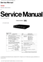
VIDEO CASSETTE RECORDER
VR8809/8709/8609/8509/8459/8409
VR5709/5609/5509/5459/5409/3609/3409
VR8809C/8769C/8719C/8609C/8509C/8459C/8409C
VR5809C/5709C/5609C/5509C/5459C/5409C/3609C/3409C
SV-C120UM/C95UM/C70UM/C60UM/C45UM
SV-C100UP/C60P/C50UP/C141P/C61P
SV-C106P/C56P/C151P/C45P/C123P/C63P
SV-C105P/C55P/C25P/SV-C15P/SP-C15P
SV-C142P/C122P/C90P/C52P/C40P/C22P
SERVICE
1. Precautions
2. Alignment and Adjustment
3. Exploded View and Parts List
4. Electrical Parts List
5. Schematic Diagrams
Manual
VIDEO CASSETTE RECORDER
CONTENTS
For mechanical disassembly and adjustment, refer to the “Mechanical Manual” (DX-9R AC68-00001A).
MENU
MENU
MENU
MENU
VR8809/8809C/5809C/SV-C142P
VR8769C/SV-C70UM/C151P/C105P/C60P
VR8709/5709/8719C/5709C/SV-C120UM/C60UM/C100UP/C50UP/C141P/C123P/C63P/C61P
VR8609/8509/5609/5509/3609/8609C/8509C/5609C/5509C/3609C/SV-C122P/C106P/C56P/C55P/C52P/C25P/C22P
VR8409/5409/3409/8409C/5409C/3409C/SV-C90P/C40P/C15P/SP-C15P
VR8459/5459/8459C/5459C/SV-C95UM/C45UM/C45P
SERVICE MANUAL
VR8809/5709/8809C/5809C/SV
-C120UM/C100UP/C1414P/C142P/C105P
ELECTRONICS
© Samsung Electronics Co., Ltd.
NOV. 1998
Printed in Korea
AC68-00099A
Summary of Contents for 3409
Page 18: ...Exploded View and Parts List 3 8 Samsung Electronics MEMO ...
Page 28: ...4 10 Samsung Electronics Electrical Parts List MEMO ...
Page 36: ...Schematic Diagrams 5 8 Samsung Electronics 5 6 Audio Video ...
Page 37: ...Schematic Diagrams Samsung Electronics 5 9 5 7 Hi Fi MTS ...
Page 38: ...Schematic Diagrams 5 10 Samsung Electronics 5 8 TM Block Input Ouput ...
Page 39: ...Schematic Diagrams Samsung Electronics 5 11 LED MODULE LED LAMP 5 9 Display ...
Page 40: ...Schematic Diagrams 5 12 Samsung Electronics 5 10 Remote Control Multi TV ...
Page 41: ...Schematic Diagrams Samsung Electronics 5 13 5 11 Remote Control VCR Only ...
Page 42: ...5 14 Samsung Electronics MEMO ...
Page 67: ...2 6 Samsung Electronics Alignment and Adjustment MEMO ...