background image

Confidential


English 8/2019. Rev 0.0 


LIB System for UPS 


Installation Manual 

(136S)


Summary of Contents for 136S

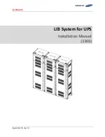
Page 1: ...Confidential English 8 2019 Rev 0 0 LIB System for UPS Installation Manual 136S ...

Page 2: ...Confidential English 8 2019 Rev 0 0 Read this manual carefully before starting to install the battery system Keep these instructions for future reference ...

Page 3: ...publication is to be used for any other purpose and it is not to be reproduced copied disclosed transmitted stored in a retrieval system or translated into any human or computer language in any form by any means in whole or in part without prior written consent of SAMSUNG SDI Co Ltd Although every possible effort has been made to ensure the accuracy of this document SAMSUNG SDI Co Ltd assumes no r...

Page 4: ...Confidential English 8 2019 Rev 0 0 ...

Page 5: ...ure to comply with the instructions with this symbol may result in a serious accident causing death or a severe injury WARNING Failure to comply with the instructions with this symbol may result in a serious accident causing a severe injury CAUTION Failure to comply with the instructions with this symbol may result in minor or moderate injury NOTICE Provides information considered important but no...

Page 6: ...ans should perform annual preventive maintenance Only qualified personnel who are familiar with the batteries and safety precautions should perform installation or maintenance of the battery Do not allow unauthorized personnel to contact the batteries Safety Precautions The following precautions provide general safety guidelines that should be followed when working with or near the Energy Storage ...

Page 7: ... that there is a serious risk of injury while working around and in equipment enclosures CAUTION STATIC SENSITIVE Electronic appliances can be damaged by electrostatic discharge Proper handling procedures are required Be sure to wear a grounded anti static wrist strap and to discharge static electricity by touching a grounded surface near the equipment before touching any system components Dangero...

Page 8: ... presented in SAMSUNG SDI safety documentation Before entering potentially hazardous areas or beginning work on the ESS complete the following tasks Identify and wear protective clothing and shoes Identify and isolate all power and stored energy sources Apply appropriate lock out tag out devices When applying lock out tag out to the ESS do not touch anything within the enclosure except as specific...

Page 9: ...quipment malfunction only adequately trained personnel should modify any programmable machine WARNING Always ensure that applicable standards and regulations are followed and only properly certified equipment is used as a critical component of a safety system Never assume that a safety critical control loop is functioning correctly ...

Page 10: ...Important Safety Instructions Confidential vi English 8 2019 Rev 0 0 ...

Page 11: ...embly Type A Type B 10 2 1 4 Rack Frame 17 3 Installing the Product 18 3 1 Grounding the Battery System 18 3 2 Arc Flash Calculations 19 3 3 Installation Procedure 20 3 4 Preparation Stage Procedure 22 3 5 Preparation Stage Unpacking 23 3 6 Preparation Stage Ground Wire and Tools 24 3 6 1 Ground Wires 24 3 6 2 Ground Wire Fasteners 24 3 6 3 Rack Fasteners Anchors 24 3 6 4 Multiple Rack Fasteners 2...

Page 12: ... 85 3 10 7 SMPS Assembly and SMU Power Cable Connection 97 3 10 8 SMPS Assembly and SMU Signal Cable Connection 98 3 10 9 SMPS Assembly AC Input Connection 100 3 10 10 DC Link Cable Connection 106 3 10 11 AC Input Commissioning 109 3 10 12 BMS Configuration 110 3 10 13 Communication Check 125 3 10 14 Reinstall the Front Door 132 3 10 15 Reinstall the Front Panel 133 3 10 16 Switching on the MCCB 1...

Page 13: ...ble 2 10 Dry Contact Operation Customer ID 2 15 Table 3 1 Estimated time for installation based on 136S 3P installation 21 Table 3 2 Parts for 136S 3P Rack 23 Table 3 3 Ground Wire Specifications 24 Table 3 4 Ground Wire Fastener Specification 24 Table 3 5 Rack Fastener Specifications 24 Table 3 6 Rack Fastener Specifications Side by side 24 Table 3 7 Recommended Tools and Instruments 25 Table 3 8...

Page 14: ...r panel hooks four 34 Figure 3 11 Rack Anchoring Points 4 EA 34 Figure 3 12 Holes on the sides of the rack six 35 Figure 3 13 Reattaching the Side Panels four hooks and six screws for each panel 36 Figure 3 14 Reattaching the Rear Panels 37 Figure 3 15 Front door ajar 39 Figure 3 16 Removing the earth cable 39 Figure 3 17 Removing the front door 40 Figure 3 18 All doors and front panels removed 40...

Page 15: ...h Battery Modules 8 s Front Cover 67 Figure 3 63 Remove Battery Modules 10 s Front Cover 68 Figure 3 64 Connect Battery Module 9 B and Battery Module 10 B 68 Figure 3 65 Reattach Battery Module 9 s Front Cover 69 Figure 3 66 Remove Battery Module 11 s Front Cover 69 Figure 3 67 Connect Battery Module 10 B and Battery Module 11 B 70 Figure 3 68 Reattach Battery Module 10 s Front Cover 71 Figure 3 6...

Page 16: ...Assembly 3 Phase Type A 100 Figure 3 117 AC Input Terminals of SMPS Assembly 3 Phase Type B 100 Figure 3 118 AC Input Terminals of SMPS Assembly 1 Phase Type A 101 Figure 3 119 AC Input Terminals of SMPS Assembly 1 Phase Type B 101 Figure 3 120 SMPS Assembly 3 Phase Type A AC Input Terminals with Cables Attached 102 Figure 3 121 SMPS Assembly 3 Phase Type B AC Input Terminals with Cables Attached ...

Page 17: ... 3 155 Open Change adapter settings 126 Figure 3 156 Open Properties for Local Area Connection 127 Figure 3 157 Open Properties for Internet Protocol Version 4 TCP IPv4 127 Figure 3 158 Setting the Computer s IP address 128 Figure 3 159 BATTMON Icon 129 Figure 3 160 BATTMON Splash Window 129 Figure 3 161 System BMS Monitor Setting 129 Figure 3 162 System and Rack Information 130 Figure 3 163 Log s...

Page 18: ...Confidential Table of Contents viii English 8 2019 Rev 0 0 ...

Page 19: ...ructions in this manual are based on assembly of a three cabinet system Other configurations are possible and the instructions can be reduced or expanded to accommodate installation of those systems 1 2 Target Audience This installation manual is intended for system administrators and operators who install and configure the product 1 3 Organization This manual is composed of the following chapters...

Page 20: ...1 About this Manual Confidential 2 English 8 2019 Rev 0 0 1 4 Revision History Rev Description Author Date 0 0 First Draft 2019 08 20 Approved By Name Signature Date Reviewers Name Signature Date ...

Page 21: ...nal Defibrillator BMS Battery Management System EHS Environmental Health and Safety ESS Energy Storage System LOTO LOCK OUT TAG OUT OT Overtemperature OVP Overvoltage Protection PCS Power Conversion System SMU String Management Unit SMPS Switched Mode Power Supply SOC State Of Charge SOH State Of Health SG Switchgear UT Undertemperature UVP Undervoltage Protection UPS Uninterruptible Power Supply ...

Page 22: ...ion please refer to the product specification 2 1 Major Components This product has the following components Battery Module Type A Type B SMU Rack BMS Embedded in SMU Rack Frame SMPS Assembly Type A Type B System BMS Embedded in SMPS Assembly Type A Refer to the Product Specification document for detailed specifications of the components ...

Page 23: ...ve commands to control cell balancing There are two types of 8S1P Battery Module depending on the position of terminal s polarity Type A s plus terminal is on the right side Type B is on the left Type A EM2031AE00XA X 1 3 X 1 for specific customer customer SKU serial number barcode SDI serial number barcode X 3 for general customer SDI serial number barcode only Type B EM2031AE00YA Y 2 4 Y 2 for s...

Page 24: ...2 Product Description Confidential 6 English 8 2019 Rev 0 0 Battery Module Type B Isometric Battery Module Type B Front Front cover removed Figure 2 2 Battery Module Type B ...

Page 25: ...te of charge SOC and state of health SOH of the battery system Key components in the SMU are Rack BMS MCCB and shunt resistor Rack BMS is the main controller that takes all data from the Module BMS measures the string voltage and current determines the state of the battery and controls the MCCB accordingly UL V049 0011XA X A B X A for general customer SDI serial number barcode only X B for specifi...

Page 26: ...Breaker Switch Connector Description Item Part Name Description Connector J21SPM 04V KX Harness Housing J21SF 04V KX L Harness Terminal SJ2F 01GF P1 0 AWG 20 24 Pin No Pin Name Function 1 Normal Open 2 Common 3 Normal Close 4 P and P terminal blocks connect to the DC link from the UPS Cable and lug terminals should be selected according to the terminal block s size and material Figure 2 5 Terminal...

Page 27: ...Terminal Block Front Top View Cover Opened Closed Table 2 2 Terminal Block Description Item Detail Description Conducting Material Cu C1100 Insulating Material Guide PA66 GF25 Insulating Material Cover PC Conductive Area 32 5mm x 40 0mm Rated Current 473A Calculated in accordance with DIN 43670 MELSON BOTH equation ...

Page 28: ... for general customer SMPS Assembly houses the System BMS and SMPS which provides power to the System BMS and SMU Two options are available for the SMPS depending on the AC input range and cabling 3 phase and 1 phase The System BMS assembly provides data to the external systems i e building management system UPS etc while controlling and monitoring all connected Rack BMS There are two types of SMP...

Page 29: ...hase AC Input SMPS Assembly with 1 Phase AC Input Type B without System BMS Figure 2 8 SMPS Assembly Type B Figure 2 9 Front View of SMPS Assembly Type A 3 Phase Input Figure 2 10 Front View of SMPS Assembly Type A 1 Phase Input Figure 2 11 SMPS Assembly Type A System BMS Connections ...

Page 30: ...2 Product Description Confidential 12 English 8 2019 Rev 0 0 Figure 2 12 Front View of SMPS Assembly Type B 1 Phase Input ...

Page 31: ...purpose only Left 2 Left 3 Left 4 Left 5 Left 6 Left 7 Left 8 Right 1 RS485 A Rx Short to Tx externally Right 2 RS485 B Rx Short to Rx externally Right 3 RS485 Z Tx Short to Rx externally Right 4 Right 5 Right 6 RS485 Y Tx Right 7 Right 8 GND Table 2 4 TCP IP Connector Description Item Part Name Description Connector VS 08 BU RJ45 LP 1 PHOENIX CONTACT Harness Housing RJ45 Harness Terminal RJ45 Pin...

Page 32: ... 0 COM 2B DRY CONTACT 0 NO 3B DRY CONTACT 1 NC 4B DRY CONTACT 2 COM 5B DRY CONTACT 2 NO 6B DRY CONTACT IN Table 2 6 AC Terminal Description 3 phase Item Part Name Description Terminal Block SL3T 4P Seoil Electronics Terminals Ring terminal 320 575VAC 6A Pin No Pin Name Function 1 L1 3 phase AC L1 2 L2 3 phase AC L2 3 L3 3 phase AC L3 4 PE Table 2 7 AC Terminal Description 1 phase Item Part Name De...

Page 33: ... Common Voltage Imbalance Error Voltage Sensing Error Under Temperature protection Temperature Imbalance Error B3 Minor Normal Close A3 Minor Normal Open B4 MCCB Status Common All MCCBs are off 4A 4B is closed One of MCCB is on 5B 4B is closed A4 MCCB Status Normal Close B5 MCCB Status Normal Open A5 Reserved B6 Input Set Condition UPS opens B6 A6 contacts for more than 3 second Action Battery MCC...

Page 34: ...ssembly 1 Phase Only Item Part Name Description Connector J21SPM 04V KX Harness Housing J21SF 04V KX L Harness Terminal SJ2F 01GF P1 0 AWG 20 24 Pin No Pin Name Function 1 SMPS 1 STATUS SMPS 1 status 2 SMPS 1 STATUS SMPS 1 status 3 SMPS 2 STATUS SMPS 2 status 4 SMPS 2 STATUS SMPS 2 status ...

Page 35: ...modules SMU and SMPS assembly and provides ground connections for SMU and SMPS Assembly Grounding cable busbar for the rack frame is necessary for the SMU and SMPS Assembly as they are grounded to the rack frame when installed An equipment grounding conductor is required to ground the rack frames together and to the UPS module Figure 2 13 Rack Frame ...

Page 36: ...llation CAUTION If available use a mechanical lift for lifting heavy 22 kg 50 lb components If there is no lift two or three workers must move items weighing more than 22 kg 50 lb The ambient temperature range must be 23 C 5 C during installation 3 1 Grounding the Battery System WARNING SHOCK HAZARD Verify with a voltmeter that no power is present on the system before beginning work on the battery...

Page 37: ...ace The following battery system is assumed to estimate the worst case scenario Battery configuration 136S Battery voltage 571 2V Battery internal resistance AC IR 65mohm Arc flash related calculation based on this battery system is as follows Bolted fault current Ibf 9000A 1 2 Bolted fault current 1 2 Ibf 4500A Protective device clearing time Tarc 6ms Protective device current interrupt capabilit...

Page 38: ...onnections Rack Installation Stage Transport the battery modules to the installation location Insert the SMU in the rack frame Insert the SMPS Assembly in the rack frame After all components are inserted in the rack frame attach them to the rack frame Place the battery modules in the rack frame Connect the busbars Connect the signal cables from SMU to module and module to module Connect the signal...

Page 39: ... HH MM 1 Unpacking 00 30 00 30 2 Inspection 01 00 01 30 3 Rack Anchoring 04 00 05 30 4 Rack Installation Battery Module 00 20 05 50 SMU 00 10 06 00 SMPS Assembly 00 10 06 10 Rack Fuse Assembly 00 30 06 40 Busbar 01 00 07 40 Signal Cables 00 20 08 00 Power and Control Cables 00 20 08 20 AC Input Installation 00 20 08 40 Cable Installation 00 10 08 50 BMS Configuration 00 10 09 00 ...

Page 40: ...d instruments for installation 2 Check the arrival schedule of the parts required 3 Unpack the equipment 4 Inspect the equipment WARNING Do not wear watches rings jewelry or any other metal objects Wear electrically insulated gloves and safety shoes CAUTION Store the product in a dust free place with the moisture level of below 60 and the temperature level of 23 C 5 C Keep components out of direct...

Page 41: ...tween modules 14 and 15 14 FUSE BUSBAR LEFT UPPER V050 00002A 3 Connect between modules 14 and 15 15 FUSE BUSBAR LEFT LOWER V050 00001A 3 Connect between modules 14 and 15 16 FUSE BUSBAR RIGHT UPPER V050 00003A 3 Connect between modules 5 and 6 17 FUSE BUSBAR RIGHT LOWER V050 00004A 3 Connect between modules 5 and 6 18 WIREASSYRACKTOMODULE V046 0005BA 3 Connect Battery Module 1 and SMU 19 WIREASSY...

Page 42: ...ch Material M12 30L 70 Grade 7 1 25 mm 0 05 in SS304 3 6 3 Rack Fasteners Anchors Specifications for the rack fastener screws for anchoring the rack frame to the floor are Table 3 5 Rack Fastener Specifications3 Size Hardness Thread Pitch Material M16 L Bottom Anchor 70 Grade 7 2 0 mm 0 08 in SS304 3 6 4 Multiple Rack Fasteners Rack fasteners are factory provided Refer to Table 3 2 Parts for 136S ...

Page 43: ...s to the rack frames 5 1 6 1Nm 50 60 kgf cm 2 Torque Limiter For use with torque wrench 3 Phillips Screwdriver or Bit To fasten SMU and SMPS assemblies to the rack frames M5 Tip 4 Box Cutter Opening boxes 5 Forklift Moving rack frames and pallets containing modules and SMU 6 Insulated Torque Wrench Installing a high current cable 10 50 N m 100 500 kgf cm 7 Insulated Sockets 13 mm 17mm and 19mm Ins...

Page 44: ...3 Installing the Product Confidential 26 English 8 2019 Rev 0 0 No Items Usage Appearance 10 Battery Tester Measure battery module s voltage and internal impedance ...

Page 45: ...ation check for Physical damage to the exterior Damaged or protruding screws Proper voltage and internal impedance of the battery modules using the battery tester Table 3 8 Module Voltage and Internal Impedance No Items Value 1 Voltage Check 28 712 29 104V 2 Internal Impedance Check 3 0 4 3 mΩ After completion install the battery module in the previously installed rack or return the battery module...

Page 46: ...MPS assembly After transporting the SMPS Assembly to its installation location check for Physical damage Paint peeling Damaged or protruding screws After completion install the SMPS in the previously installed rack or return the SMPS to its original packing for protection during storage ...

Page 47: ... all four anchor points of the rack must be installed To reduce the product footprint the racks can be installed side by side and rear to rear against a wall or next to another rack In this case only two anchor points on the front side of each rack can be installed Proper cooling and ventilation of the installed area is recommended for racks installed with no side and rear clearance Front side of ...

Page 48: ...ended 4 All Telcordia Zone 4 Workable distance 800 recommended 0 Workable distance 800 recommended Workable distance 1000 recommended Two anchor points not rated for seismic event Four anchor points Telcordia Zone 4 Figure 3 2 Clearance Distance for Single Rack Frame Two anchor points not rated for seismic event Four anchor points Telcordia Zone 4 Figure 3 3 Clearance Distance for Multiple Rack Fr...

Page 49: ...e by Side and Rear to Rear 1 After unpacking the rack frame transport it to its installation location 2 Remove the front panels side panels and rear panel from the rack frame Unscrew the screws on each panel and lift the panel to undo the hooks to the frame on each panel Do not misplace the screws as they are needed when installing the panels back after anchoring the rack frame Figure 3 5 Front pa...

Page 50: ...3 Installing the Product Confidential 32 English 8 2019 Rev 0 0 Figure 3 6 Front panel hooks four Figure 3 7 Side panel screws six ...

Page 51: ...Confidential 3 Installing the Product English 8 2019 Rev 0 0 33 Figure 3 8 Side panel hooks four Figure 3 9 Rear panel screws eight ...

Page 52: ...at the holes in the frame and anchoring points are aligned 4 Connect four anchoring points on the bottom of the rack NOTICE Anchor the frame with M16 bolts and nuts The fastening torque should be 140Nm 1 425kgf cm Check the rack and other parts for distortion caused by unpacking Figure 3 11 Rack Anchoring Points 4 EA Bottom of the Rack Frame ...

Page 53: ...o 30Nm 300kgf cm Figure 3 12 Holes on the sides of the rack six 6 Optional step After all the rack frames are anchored and connected reattach the side panels to the outermost rack frames using the provided M5 Screws for each side panel Fasten the screws using torque of 5 1 6 1 Nm 50 60 kgf cm Make sure all the hooks are inserted to the slot and the panel is flush with the rack frame before screwin...

Page 54: ...s four hooks and six screws for each panel 7 Reattach the rear panels to the rack frames using the provided M5 Screws for each rear panel Fasten the screws using torque of 5 1 6 1 Nm 50 60 kgf cm Make sure all the hooks are inserted to the slot and the panel is flush with the rack frame before screwing ...

Page 55: ...Confidential 3 Installing the Product English 8 2019 Rev 0 0 37 Figure 3 14 Reattaching the Rear Panels 8 Front panels will be reattached after all the components are installed ...

Page 56: ...d for any work on this energized equipment WARNING Sharp Edges Wear gloves and other protective gear to prevent injury WARNING Pinch Point Use caution when working in the enclosure to prevent injury CAUTION Heavy Object Can cause muscle strain or back injury Use lifting aids and proper lifting techniques when moving trays batteries and other heavy objects ...

Page 57: ... front door of the panel using the provided key Figure 3 15 Front door ajar 2 Remove the earth cable from the rack frame to the front door Do not misplace the two screws and the earth cable Figure 3 16 Removing the earth cable 3 Lift the front door to remove it from its hinge Do not misplace the door ...

Page 58: ...3 Installing the Product Confidential 40 English 8 2019 Rev 0 0 Figure 3 17 Removing the front door 4 If installing more than one rack remove all the doors Figure 3 18 All doors and front panels removed ...

Page 59: ...Verify that the torque setting is correct 1 Insert the SMU through the front of the rack as shown in Figure 3 19 Inserting SMU Figure 3 19 Inserting SMU 2 After all SMU s are inserted in the rack frames attach each to the rack frame with four M5 x 10L bolts Torque 5 1 6 1 Nm 50 60 kgf cm Figure 3 20 Attaching a SMU to a Rack Frame 3 After all SMU s are inserted into the rack frame connect the grou...

Page 60: ...ential 42 English 8 2019 Rev 0 0 NOTICE Connect a ground cable between the SMU and the Rack Frame SCREW M5 x 10L Torque 5 1 6 1 Nm 50 60 kgf cm Verify that the torque setting is correct Figure 3 21 Ground Cable Connection to the SMU ...

Page 61: ...0Lscrews Torque 5 1 6 1 Nm 50 60 kgf cm Verify that the torque setting is correct 5 Slide the SMPS Assembly into the rack frame on the shelf designated for the SMPS Assembly as shown below Figure 3 22 Inserting SMPS Assembly 6 After all SMPS Assemblies are inserted into the rack frames attach them to the rack frame with screws Torque 5 1 6 1 Nm 50 60 kgf cm Figure 3 23 Attaching the SMPS Assembly ...

Page 62: ...ish 8 2019 Rev 0 0 NOTICE Connect a ground cable between the SMPS Assembly and the Rack Frame with an M5 x 10L screw Torque 5 1 6 1 Nm 50 60 kgf cm Verify that the torque setting is correct Figure 3 24 Ground Cable Connection to the SMPS Assembly ...

Page 63: ...nce difference of 1 3mΩ Refer to Table 3 8 Module Voltage and Internal Impedance 3 Place the battery modules on the rack frame Important Samsung recommends installing Battery Modules in the upper shelves first and proceeding to the bottom Two Type B battery modules are inserted in the ninth shelf from the bottom Sixteen battery modules can be inserted into a rack frame as shown in Figure 3 27 Refe...

Page 64: ...h Shelf Figure 3 27 Battery Module Arrangement Two Type A Battery Modules Two Type B Battery Modules Two Type A Battery Modules Two Type B Battery Modules Two Type A Battery Modules Two Type B Battery Modules Two Type A Battery Modules Two Type B Battery Modules Two Type A Battery Modules One Type B Battery Modules ...

Page 65: ...ing modules from top to bottom The bottom shelf 1st shelf has one Type B module in the left slot as shown in Figure 3 29 Figure 3 29 Insertion of modules on 1st shelf Module 8 Module 7 Module 6 Module 5 Module 4 Module 3 Module 2 Module 1 Module 9 Module 10 Module 11 Module 12 Module 13 Module 14 Module 15 Module 16 Module 17 ...

Page 66: ...16L screws are used to assemble the busbars and fuse The fastening torque should be 30 Nm 300 kgf cm When assembling the fuse make sure the red indicator arm on the fuse is facing the front of the unit 1 Assemble the Rack fuse Bus bar assembly Rack fuse bus bar assembly is comprised of one RACKFUSE BUSBAR_R_136S one RACKFUSE BUSBAR_L_136S two SCREW M12 X 16 one FUSE COVER 1 and one FUSE Figure 3 3...

Page 67: ...emble the Fuse Busbar Left Assembly Fuse Busbar Left Assembly is comprised of one FUSE BUSBAR LEFT UPPER one one FUSE BUSBAR LEFT LOWER two SCREW M12 X 16 two FUSE COVER 2 and one FUSE Figure 3 32 Fuse Busbar Left Assembly Figure 3 33 Fuse Busbar Left Assembly Fuse Cover ...

Page 68: ...le the Fuse Busbar Right Assembly Fuse Busbar Right Assembly is comprised of one FUSE BUSBAR RIGHT UPPER one one FUSE BUSBAR RIGHT LOWER two SCREW M12 X 16 two FUSE COVER 2 and one FUSE Figure 3 34 Fuse Busbar Right Assembly Figure 3 35 Fuse Busbar Right Assembly Fuse Cover ...

Page 69: ...g with each other It is recommended not to touch the battery positive or negative terminal for the batteries with rack frame There is no evidence of dielectric breakdown because of electrical isolation between the battery positive or negative terminals and rack frame However it is recommended not to touch them for safety because It is possible to touch between battery positive and negative through...

Page 70: ...er and the SMU B terminal cover Figure 3 36 Removing the Module 1 s Cover and SMU B Terminal Cover 2 Connect SMU B and Module 1 B using BUSBAR M TO SMU SMU B terminal is connected using an M12 screw and Battery Module 1 B terminal is connected using an M8 screw Figure 3 37 Connect SMU B and Module 1 B ...

Page 71: ...l 3 Installing the Product English 8 2019 Rev 0 0 53 3 Reattach SMU s B terminal cover Figure 3 38 Restore SMU s B Terminal 4 Remove Battery Module 2 s front cover Figure 3 39 Remove Battery Module 2 s Front Cover ...

Page 72: ...Battery Module 1 B and Module 2 B using BUS BAR MAIN Connect using an M8 screw Figure 3 40 Connect Battery Module 1 B and Battery Module 2 B 6 Reattach Battery Module 1 s front cover and remove Battery Module 3 s front cover Figure 3 41 Reattach Battery Module 1 s Front Cover ...

Page 73: ...ct English 8 2019 Rev 0 0 55 Figure 3 42 Remove Battery Module 2 s Front Cover 7 Connect Battery Module 2 B and Battery Module 3 B using BUS BAR MAIN Connect using an M8 screw Figure 3 43 Connect Battery Module 2 B and Battery Module 3 B ...

Page 74: ... Confidential 56 English 8 2019 Rev 0 0 8 Reattach Battery Module 2 s front cover and remove Battery Module 4 s front cover Figure 3 44 Reattach Battery Module 2 s Front Cover Figure 3 45 Remove Battery Module 4 s Front Cover ...

Page 75: ...nfidential 3 Installing the Product English 8 2019 Rev 0 0 57 9 Connect Battery Module 3 B and Module 4 B using BUS BAR MAIN Connect using an M8 screw Figure 3 46 Connect Battery Module 3 B and Module 4 B ...

Page 76: ... Confidential 58 English 8 2019 Rev 0 0 10 Reattach Battery Module 3 s front cover and remove Battery Module 5 s front cover Figure 3 47 Reattach Battery Module 3 s Front Cover Figure 3 48 Remove Battery Module 5 s Front Cover ...

Page 77: ...l 3 Installing the Product English 8 2019 Rev 0 0 59 11 Connect Battery Module 4 B and Battery Module 5 B using BUS BAR MAIN Connect using an M8 screw Figure 3 49 Connect Battery Module 4 B and Battery Module 5 B ...

Page 78: ... Confidential 60 English 8 2019 Rev 0 0 12 Reattach Battery Module 4 s front cover and remove Battery Module 6 s front cover Figure 3 50 Reattach Battery Module 4 s Front Cover Figure 3 51 Remove Battery Module 6 s Front Cover ...

Page 79: ...talling the Product English 8 2019 Rev 0 0 61 13 Connect Battery Module 5 B and Battery Module 6 B using FUSE BUSBAR RIGHT ASSEMBLY Connect using an M8 screw Figure 3 52 Connect Battery Module 5 B and Battery Module 6 B ...

Page 80: ... Confidential 62 English 8 2019 Rev 0 0 14 Reattach Battery Module 5 s front cover and remove Battery Module 7 s front cover Figure 3 53 Reattach Battery Module 5 s Front Cover Figure 3 54 Remove Battery Module 7 s Front Cover ...

Page 81: ...l 3 Installing the Product English 8 2019 Rev 0 0 63 15 Connect Battery Module 6 B and Battery Module 7 B using BUS BAR MAIN Connect using an M8 screw Figure 3 55 Connect Battery Module 6 B and Battery Module 7 B ...

Page 82: ... Confidential 64 English 8 2019 Rev 0 0 16 Reattach Battery Module 6 s front cover and remove Battery Module 8 s front cover Figure 3 56 Reattach Battery Module 6 s Front Cover Figure 3 57 Remove Battery Module 8 s Front Cover ...

Page 83: ...y Module 7 B and Battery Module 8 B using BUS BAR MAIN Connect using an M8 screw Figure 3 58 Connect Battery Module 7 B and Battery Module 8 B 18 Reattach Battery Modules 7 s front cover and remove Battery Modules 9 s front cover Figure 3 59 Reattach Battery Modules 7 s Front Cover ...

Page 84: ...3 Installing the Product Confidential 66 English 8 2019 Rev 0 0 Figure 3 60 Remove Battery Modules 9 s Front Cover ...

Page 85: ...le 8 B and Battery Module 9 B using RACK FUSE BUSBAR ASSEMBLY Connect using an M8 screw Figure 3 61 Connect Battery Module 8 B and Battery Module 9 B 20 Reattach Battery Module 8 s front cover and remove Battery Module 10 s front cover Figure 3 62 Reattach Battery Modules 8 s Front Cover ...

Page 86: ...e Battery Modules 10 s Front Cover 21 Connect Battery Module 9 B and Battery Module 10 B using BUS BAR MAIN Connect using an M8 screw Figure 3 64 Connect Battery Module 9 B and Battery Module 10 B 22 Reattach Battery Module 9 s front cover and remove Battery Module 11 s front cover ...

Page 87: ...Confidential 3 Installing the Product English 8 2019 Rev 0 0 69 Figure 3 65 Reattach Battery Module 9 s Front Cover Figure 3 66 Remove Battery Module 11 s Front Cover ...

Page 88: ...the Product Confidential 70 English 8 2019 Rev 0 0 23 Connect Battery Module 10 B and Battery Module 11 B using BUS BAR MAIN Connect using an M8 screw Figure 3 67 Connect Battery Module 10 B and Battery Module 11 B ...

Page 89: ...ing the Product English 8 2019 Rev 0 0 71 24 Reattach Battery Module 10 s front cover and remove Module 12 s front cover Figure 3 68 Reattach Battery Module 10 s Front Cover Figure 3 69 Remove Battery Module 12 s Front Cover ...

Page 90: ...the Product Confidential 72 English 8 2019 Rev 0 0 25 Connect Battery Module 11 B and Battery Module 12 B using BUS BAR MAIN Connect using an M8 screw Figure 3 70 Connect Battery Module 11 B and Battery Module 12 B ...

Page 91: ...talling the Product English 8 2019 Rev 0 0 73 26 Reattach Battery Module 11 s front cover and remove Battery Module 13 s front cover Figure 3 71 Reattach Module 11 s Front Cover Figure 3 72 Remove Module 13 s Front Cover ...

Page 92: ... the Product Confidential 74 English 8 2019 Rev 0 0 27 Connect Battery Module 12 B and Battery Module 13 B using BUS BAR MAIN Connect using an M8 screw Figure 3 73 Connect Battery Module 12B and Battery Module 13 B ...

Page 93: ...ing the Product English 8 2019 Rev 0 0 75 28 Reattach Battery Module 12 s front cover and remove Battery Module 14 s front cover Figure 3 74 Reattach Module 12 s Front Cover Figure 3 75 Remove Battery Module 14 s Front Cover ...

Page 94: ...the Product Confidential 76 English 8 2019 Rev 0 0 29 Connect Battery Module 13 B and Battery Module 14 B using BUS BAR MAIN Connect using an M8 screw Figure 3 76 Connect Battery Module 13 B and Battery Module 14 B ...

Page 95: ...the Product English 8 2019 Rev 0 0 77 30 Reattach Battery Module 13 s front cover and remove Battery Module 15 s front cover Figure 3 77 Reattach Battery Module 13 s Front Cover Figure 3 78 Remove Battery Module 15 s Front Cover ...

Page 96: ...oduct Confidential 78 English 8 2019 Rev 0 0 31 Connect Battery Module 14 B and Battery Module 15 B using FUSE BUSBAR LEFT ASSEMBLY Connect using an M8 screw Figure 3 79 Connect Battery Module 14 B and Battery Module 15 B ...

Page 97: ...the Product English 8 2019 Rev 0 0 79 32 Reattach Battery Module 14 s front cover and remove Battery Module 16 s front cover Figure 3 80 Reattach Battery Module 14 s Front Cover Figure 3 81 Remove Battery Module 16 s Front Cover ...

Page 98: ...the Product Confidential 80 English 8 2019 Rev 0 0 33 Connect Battery Module 15 B and Battery Module 16 B using BUS BAR MAIN Connect using an M8 screw Figure 3 82 Connect Battery Module 15 B and Battery Module 16 B ...

Page 99: ...the Product English 8 2019 Rev 0 0 81 34 Reattach Battery Module 15 s front cover and remove Battery Module 17 s front cover Figure 3 83 Reattach Battery Module 15 s Front Cover Figure 3 84 Remove Battery Module 17 s Front Cover ...

Page 100: ...g the Product Confidential 82 English 8 2019 Rev 0 0 35 Connect Battery Module 16 B and Battery Module 17 B using BUS BAR MAIN Connect using M8 screw Figure 3 85 Connect Battery Module 16 B and Battery Module 17 B ...

Page 101: ...nstalling the Product English 8 2019 Rev 0 0 83 36 Reattach Battery Module 16 s front cover and remove SMU s B terminal cover Figure 3 86 Reattach Battery Module 15 s Front Cover Figure 3 87 Remove SMU B Terminal Cover ...

Page 102: ... BUSBAR M TO SMU SMU B terminal is connected using an M12xL25 screw and Module 17 B terminal is connected using an M8 screw Figure 3 88 Connect SMU B and Module 17 B 38 Reattach Battery Module 17 s front cover and SMU B terminal cover Figure 3 89 Reattach Battery Module 17 s Front Cover and SMU B Terminal Cover ...

Page 103: ... the proper signal cables as specified by the part numbers below WARNING Rack BMS Module BMS Damage Do not insert both ends of the signal cable WIRE ASSY MODULE TO MODULE 1 or WIRE ASSY MODULE TO MODULE 2 into the same Battery Module 1 Connect the signal cable WIRE ASSY RACK TO MODULE between the SMU MODULE connector and Module 1 Right Connector Figure 3 90 SMU to Module 1 Signal Cable ...

Page 104: ...IRE ASSY MODULE TO MODULE 1 from Module 1 Left Connector to Module 2 Right Connector Figure 3 91 Module 1 to Module 2 Signal Cabling 3 Connect the signal cable WIRE ASSY MODULE TO MODULE 1 from Module 2 Left Connector to Module 3 Right Connector Figure 3 92 Module 2 to Module 3 Signal Cabling ...

Page 105: ...IRE ASSY MODULE TO MODULE 1 from Module 3 Left Connector to Module 4 Right Connector Figure 3 93 Module 3 to Module 4 Signal Cabling 5 Connect the signal cable WIRE ASSY MODULE TO MODULE 1 from Module 4 Left Connector to Module 5 Right Connector Figure 3 94 Module 4 to Module 5 Signal Cabling ...

Page 106: ...IRE ASSY MODULE TO MODULE 1 from Module 5 Left Connector to Module 6 Right Connector Figure 3 95 Module 5 to Module 6 Signal Cabling 7 Connect the signal cable WIRE ASSY MODULE TO MODULE 1 from Module 6 Left Connector to Module 7 Right Connector Figure 3 96 Module 6 to Module 7 Signal Cabling ...

Page 107: ...IRE ASSY MODULE TO MODULE 1 from Module 7 Left connector to Module 8 Right connector Figure 3 97 Module 7 to Module 8 Signal Cabling 9 Connect the signal cable WIRE ASSY MODULE TO MODULE 2 from Module 8 Left Connector to Module 9 Right Connector Figure 3 98 Module 8 to Module 9 Signal Cabling ...

Page 108: ... ASSY MODULE TO MODULE 1 from Module 9 Left Connector to Module 10 Right Connector Figure 3 99 Module 9 to Module 10 Signal Cabling 11 Connect the signal cable WIRE ASSY MODULE TO MODULE 1 from Module 10 Left Connector to Module 11 Right Connector Figure 3 100 Module 10 to Module 11 Signal Cabling ...

Page 109: ...SSY MODULE TO MODULE 1 from Module 11 Left Connector to Module 12 Right Connector Figure 3 101 Module 11 to Module 12 Signal Cabling 13 Connect the signal cable WIRE ASSY MODULE TO MODULE 1 from Module 12 Left Connector to Module 13 Right Connector Figure 3 102 Module 12 to Module 13 Signal Cabling ...

Page 110: ...SSY MODULE TO MODULE 1 from Module 13 Left Connector to Module 14 Right Connector Figure 3 103 Module 13 to Module 14 Signal Cabling 15 Connect the signal cable WIRE ASSY MODULE TO MODULE 1 from Module 14 Left Connector to Module 15 Right Connector Figure 3 104 Module 14 to Module 15 Signal Cabling ...

Page 111: ...m Module 15 Left Connector to Module 16 Right Connector Figure 3 105 Module 15 to Module 16 Signal Cabling 17 Connect the signal cable WIRE ASSY MODULE TO MODULE 1 from Module 16 Left Connector to Module 17 Right Connector No connection to Module 17 Left Connector is needed Figure 3 106 Module 16 to Module 17 Signal Cabling ...

Page 112: ...TO RACK 2 between each rack s SMU Push the pre punched hole to pass the cable through a circular hole in the side of the rack frame and through the opening above Module 1 and Module 16 NOTICE See the examples for correct signal cable wire connections for both left and right rack alignments Figure 3 107 Pre Punched Hole for Signal Cable ...

Page 113: ...English 8 2019 Rev 0 0 95 Signal Cabling Examples of Left Alignment of Trays System BMS on the left Figure 3 108 Signal Cabling Examples of Left Alignment of SMU 19 Turn the termination resistor switch on for the last SMU in the CANbus loop ...

Page 114: ...ial 96 English 8 2019 Rev 0 0 Figure 3 109 Termination Resistor Setting for Last SMU NOTICE Factory provided cables are adequate for systems with Rack Frames bolted together Different configurations may require cable length modification ...

Page 115: ...sh 8 2019 Rev 0 0 97 3 10 7 SMPS Assembly and SMU Power Cable Connection Connect the SMU DC power cables Figure 3 110 DC Power Cables from SMPS Assembly 3 Phase Type A to SMU Figure 3 111 DC Power Cables from SMPS Assembly 3 Phase Type B to SMU ...

Page 116: ...ignal cable from the SMPS Assembly to SMU WIRE ASSY RACK TO SYSTEM Figure 3 112 CAN Signal Cable Connection from SMPS Assembly 3 Phase Type A to SMU 2 Connect the MODBUS TCP IP Cable4 to the SMPS Assembly Type A Figure 3 113 TCP IP Cable Connection to SMPS Assembly 3 Connect the Dry Contact Cable to SMPS Assembly Type A 4 Not factory provided Must be provided by the installer or customer ...

Page 117: ...nfidential 3 Installing the Product English 8 2019 Rev 0 0 99 Figure 3 114 Dry Contact Cable Connection to SMPS Assembly 4 Optional Connect the SMU MCCB Cable Figure 3 115 MCCB Extra Auxiliary Connection ...

Page 118: ...lish 8 2019 Rev 0 0 3 10 9 SMPS Assembly AC Input Connection 1 Remove the protective covers from the AC input terminals Figure 3 116 AC Input Terminals of SMPS Assembly 3 Phase Type A Figure 3 117 AC Input Terminals of SMPS Assembly 3 Phase Type B ...

Page 119: ...Confidential 3 Installing the Product English 8 2019 Rev 0 0 101 Figure 3 118 AC Input Terminals of SMPS Assembly 1 Phase Type A Figure 3 119 AC Input Terminals of SMPS Assembly 1 Phase Type B ...

Page 120: ...ssembly Make sure the AC cables are not energized 5 Figure 3 120 SMPS Assembly 3 Phase Type A AC Input Terminals with Cables Attached Figure 3 121 SMPS Assembly 3 Phase Type B AC Input Terminals with Cables Attached 5 AC Cables are not factory provided They must be provided by the installer or customer ...

Page 121: ...e 3 122 SMPS Assembly 1 Phase Type A AC Input Terminals with Cables Attached Figure 3 123 SMPS Assembly 1 Phase Type B AC Input Terminals with Cables Attached 3 Reattach the protective covers to the AC input Figure 3 124 AC Input Terminals of SMPS Assembly 3 Phase Type A ...

Page 122: ...3 Installing the Product Confidential 104 English 8 2019 Rev 0 0 Figure 3 125 AC Input Terminals of SMPS Assembly 3 Phase Type B Figure 3 126 AC Input Terminals of SMPS Assembly 1 Phase Type A ...

Page 123: ...Confidential 3 Installing the Product English 8 2019 Rev 0 0 105 Figure 3 127 AC Input Terminals of SMPS Assembly 1 Phase Type B ...

Page 124: ...on 1 Connect the ground cables Figure 3 128 Grounding Points 2 EA NOTICE Connect the rack ground wire with an M12 screw Rack ground screws and cables are not factory provided and must be provided by the installer or customer The fastening torque should be 30Nm 300kgf cm 45 mm Pitch Between Holes ...

Page 125: ...ning this step In this step the battery and UPS are isolated by the SMU because the circuit breaker in the SMU is opened NOTICE Connect the high voltage terminals using an M12 bolt The fastening torque should be 30 Nm 300 kgf cm Figure 3 129 Connecting the DC Link High Current Terminals 3 Special case if connecting the battery system in three wire system connect two racks to the three wire DC bus ...

Page 126: ...oduct Confidential 108 English 8 2019 Rev 0 0 After installation is complete check the following Bolt fastening condition Screw fastening torque by sampling High voltage cable connection Module connections SMU connections ...

Page 127: ...dential 3 Installing the Product English 8 2019 Rev 0 0 109 3 10 11 AC Input Commissioning When the installation of the battery system is complete SMPS Assembly s AC inputs must be powered to turn the BMS on ...

Page 128: ...e RJ45 8 pin and D SUB female 9 pin Connect between System BMS and USB to CAN device Must be made by the customer or installer as described below Table 3 12 System BMS Configuration Cable Pin Map 3 Ethernet Cable RJ45 8 pin and RJ45 8 pin Must be made by the customer or installer as described below Table 3 13 System BMS Communication Cable Pin Map 4 IXXAT USB to CAN V2 Must be provided by the cust...

Page 129: ...e made by the customer or installer according to the following PIN map Figure 3 130 Rack BMS Configuration Cable Pin Map Table 3 11 Rack BMS Configuration Cable Pin Map Connection A Connection B Connector Pin No Signal Connector Pin No Signal D SUB Female 1 J21SF 06V KX L 1A GND Ground 2 CAN Low 2A 3 CAN Ground 3A 4 1B CAN Low 5 2B CAN High 6 3B 7 CAN High 8 9 ...

Page 130: ...2 System BMS Configuration Cable Pin Map Connection A Connection B Connector Pin No Signal Connector Pin No Signal D SUB Female 1 RJ45 1 CAN High 2 CAN Low 2 CAN Low 3 CAN Ground 3 CAN Ground 4 4 5 5 6 6 7 CAN High 7 8 8 9 NOTICE A 120 termination resistor must be inserted between the pins for No 2 and No 7 in the D SUB Female ...

Page 131: ...d configuration files provided by Samsung SDI is as follows No Items Description 1 BATTMON_Setup_Vxxxx zip Installation file for the BATTMON application 2 R_ Rack BMS part name xml Rack BMS configuration parameter file 3 S_ System BMS part name xml System BMS configuration parameter file Disclaimer BATTMON software provided by Samsung SDI can be used only to configure the Rack BMS and System BMS d...

Page 132: ... steps below for installing BATTMON program Unzip the provided compressed file Locate the unzipped folder Locate and open setup exe Click Next to continue Check the folder setting and click Next to continue Click Next to continue Check the installation progress Click Close to finish installation Locate and open BATTMON ...

Page 133: ...ation mode Double click the icon on the upper left part of the BATTMON window Figure 3 133 BATTMON Splash Window When prompted for a password enter install not case sensitive and press enter Figure 3 134 Installer Access Password Click the Add parameter file icon under the SYSTEM BMS part to add the System BMS parameter files ...

Page 134: ...ess OK to skip the warning Figure 3 136 Warning Pop up Window Find and select the System BMS parameter file Click Open to load the file to BATTMON Figure 3 137 Selecting System BMS Configuration Parameter File Click the Add parameter file icon under the RACK BMS part to add the Rack BMS parameter files ...

Page 135: ... Figure 3 138 BATTMON Splash Window Warning Pop up Window Press OK to skip the warning Figure 3 139 Warning Pop up Window Find and select the Rack BMS parameter file Click Open to load the file to BATTMON Figure 3 140 Selecting Rack BMS Configuration Parameter File ...

Page 136: ...k System Important If multiple racks are installed the Rack BMS CAN ID s must be set individually Turn off all other Rack BMS by disconnecting the SMU DC power cable while configuring the Rack BMS Reconnect all SMU DC power cables after configuring all Rack BMS units 2 Connect the Computer to Rack BMS with IXXAT USB to CAN device and Rack BMS configuration cable Disconnect all CAN connections and ...

Page 137: ...g the Product English 8 2019 Rev 0 0 119 Figure 3 143 Rack BMS termination switch and CAN cable connection 3 Run BATTMON exe Figure 3 144 BATTMON Icon 4 Click the CONFIG button under the RACK BMS part to configure the Rack BMS ...

Page 138: ... to your computer the CONNECT button will not work 6 Select RACK 001 from the drop down menu This is the factory default setting Click on the checkbox to write the value Double click the values under Write Value column to change the write values For CAN ID 1 write value is 0x2001 For CAN ID 2 the value is 0x2002 Write the number of module BMS per rack In case of 136S battery the number of module B...

Page 139: ...the system BMS To set the second Rack BMS enter 0x2002 under Write Value for the second rack BMS To read and configure the Rack BMS after setting the CAN ID the correct CAN ID setting must be selected from the drop down menu Module BMS counter per 1 Rack is the number of modules connected to the Rack BMS Its range is 1 32 For example in case of 136S Rack the value is 17 and in case of 128S Rack th...

Page 140: ...onnect both an Ethernet cable and a configuration cable from the system BMS to your computer as shown in the figure below Figure 3 148 Cable Connections for System BMS Configuration 2 Run BATTMON exe Figure 3 149 BATTMON Icon 3 Click the CONFIG button under the SYSTEM BMS part to configure the System BMS ...

Page 141: ...vice is shown disconnect the IXXAT USB to CAN device from the computer and reinstall the device driver Figure 3 151 SYSTEM BMS CONFIG connection window NOTICE When the USB to CAN device is not connected to your computer the CONNECT button will not work 5 Click on the checkbox to write the value Double click the values under Write Value column to change the write values ...

Page 142: ...t 17 91 30 246 502 by default subnet mask 255 255 224 0 by default and gateway 17 91 1 2 by default should be changed according to your network environment Set the port number to the factory default values Port 01 502 Port 02 602 Port 03 702 RTU items set to the factory default values Baud rate 0 Parity 1 Slave ID 0x27 Operation Neutral Control Enable Set to 0 if all racks are connected in paralle...

Page 143: ... 1 PC s IP Setting for Communication with the System BMS NOTICE The following guide for PC s IP setting is made with Microsoft Windows 7 Other versions of Windows may be different 1 Checking the Data of the System BMS requires changing the IP settings in the notebook PC to be used 2 Click the START button in the desktop s status bar to open the Start menu 3 Click Network If Network menu is not ava...

Page 144: ...ling the Product Confidential 126 English 8 2019 Rev 0 0 Figure 3 154 Open Network and Sharing Center 5 When the following window appears click Change adapter settings Figure 3 155 Open Change adapter settings ...

Page 145: ...k Local Area Connection When the popup menu appears click Properties Figure 3 156 Open Properties for Local Area Connection 7 When the Local Area Connection Properties window appears select Internet Protocol Version 4 TCP IPv4 and then click Properties Figure 3 157 Open Properties for Internet Protocol Version 4 TCP IPv4 ...

Page 146: ... Installing the Product Confidential 128 English 8 2019 Rev 0 0 8 When the following window appears change the IP address that fits the network environment Figure 3 158 Setting the Computer s IP address ...

Page 147: ...unning BATTMON 2 Run BATTMON exe Figure 3 159 BATTMON Icon 3 Click Monitor under the SYSTEM BMS part Figure 3 160 BATTMON Splash Window 4 Enter the TCP IP settings according to the value set during the configuration Click the Connect button Figure 3 161 System BMS Monitor Setting 5 All connected rack s information and cell s information can be seen in the monitoring window ...

Page 148: ...logging parameters Figure 3 162 System and Rack Information Figure 3 163 Log setting Check the box for all rack s cell info log Cell info is logged once every 30 seconds for each rack 6 Select CELL INFO tab to monitor the cell information Enter the number of module BMS set during the configuration in the display counter If more than one rack is connected cycle through each rack s CAN ID using the ...

Page 149: ...Confidential 3 Installing the Product English 8 2019 Rev 0 0 131 Figure 3 164 Cell Information ...

Page 150: ...urther access to high voltage parts of the SMU and SMPS Assembly 2 Align the hinges on the rack frame and front door and slide the door down Figure 3 165 Reattaching the Front Door 3 Reattach the earth cable from the rack frame to the front door Figure 3 166 Reattaching the earth cable 4 Close and lock the front door using the provided key Do not misplace the key ...

Page 151: ...ate the hooks that hold the front panel to the slots in the rack frame and insert the front panel to the rack frame Make sure all the hooks are inserted to the slot and the panel is flush with the rack frame before screwing Figure 3 167 Front panel hooks four 3 Screw in the front panel using the provided M5 screws for each front panel Fasten the screws using torque of 5 1 6 1 Nm 50 60 kgf cm Figur...

Page 152: ...oduct Specification and Operation and Maintenance Manual for information on the indicator LED CAUTION Follow the instruction and guidelines for the UPS on connecting the battery to the UPS before switching on the MCCB The MCCB in the SMU should be in the TRIP position during installation Figure 3 169 MCCB Handle in Trip Position Shift the handle of the MCCB to OFF Figure 3 170 MCCB Handle in Off P...

Page 153: ...Confidential Memo ...

Page 154: ...Confidential Memo ...

Page 155: ...Confidential Memo ...

Page 156: ...www SamsungSDI com ...

Reviews: