background image


Summary of Contents for 1000P

Page 1: ... ...

Page 2: ... 0 12345678 9 9 9 9 9 9 ABC ABC ABC ABC ABCDEF GH IJK ILM NO A A5PQRS TU V W X Y V W X Y V W X Y V W X Y V W X Y V W X Y Z W Z W Z W Z W Z W V ...

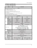
Page 3: ... _ abcdef gh gh gh gh fi fi fi fi jk lk mn op g qp r sp t uvw xyz y t 8 g g vw xyz y g ...

Page 4: ... 0123456789 AB CDEF GH IJ 89KLMN OP OP OP OP OP Q OP Q OP Q OP Q RS RS RS RS T234567U VW XYZ ...

Page 5: ... OP OP OP OP OP Q OP Q OP Q OP Q RS RS RS RS _ a J bJcd6 eRS fgZ TbJ V hijk 6 eRS lZm V I ...

Page 6: ...5 1 5 Exploded View Part List 5 Exploded View Part List 5 1 LP08PSMSB XF Exploded View 800P T0003 M0003 M0215 M0013 T0265 BN96 12518A T0175 M0014 T0145 T0531 ...

Page 7: ... OTZ W W LP08PSMSB EN W W 1 SA M0215 BN07 00761A LCD PANEL AT080TN03 IN080038 6Bit Hi FRC 1 SA T0003 BN96 12119A ASSY COVER P FRONT SWAN 8 ABS PMMA BLAC 1 SA T0145 BN96 12124A ASSY COVER P BOTTOM SWAN 8 PC CLEAR 1 SA T0175 BN96 12068A ASSY SPEAKER P 8ohm 2pin 0 7W 50mm Unit 2 SA T0265 BN96 12359A ASSY COVER P TOP 800P ABS PMMA BK27 1 SA T0531 BN63 06179A COVER BOTTOM SWAN 8 PC CLEAR TTP01 1 SA BN9...

Page 8: ...4 D0254 0402 000553 DIODE SCHOTTKY SS24 B240 40V 2000mA DO 2 1 SA 4 MZD1 0403 001411 DIODE ZENER 5 49 5 73V 200mW SOD 323 TP 6 SA 4 0406 001181 DIODE TVS NUP4201MR6 6 V 500W TSOP 6 2 SA 4 Q409 0505 002234 FET SILICON PMV65XP P 20V 3 9A 0 076oh 2 SA 4 IC112 1103 000129 IC EEPROM 24C02 2Kbit 256x8 SOP 8P 5x4mm 1 SA 4 1105 002030 IC DDR SDRAM NT5DS32M16CS 5T DDR SDRAM 5 1 SA 4 T0087 1203 002302 IC PO...

Page 9: ...TP 201 2 SNA 4 AD480 2203 005437 C CER CHIP 10000nF 80 20 10V Y5V 3216 1 SNA 4 AD480 2203 005809 C CER CHIP 1000nF 10 16V X7R TP 2012 4 SC 4 EC9 2203 005834 C CER CHIP 22000nF 80 20 10V Y5V 3216 6 SA 4 AD480 2203 006024 C CER CHIP 2200nF 10 10V X7R 2012 2 SNA 4 C102 2203 006158 C CER CHIP 100nF 10 16V X7R 1005 4 SNA 4 AD480 2203 006333 C CER CHIP 10000nF 20 16V X5R TP 3216 27 SNA 4 AD480 2203 0063...

Page 10: ...H 1005 1 SA 4 T0052 2703 002365 INDUCTOR SMD 1 2nH 0 3nH 1005 1 SA 4 BN97 03927V ASSY MICOM EPROM_W W P BN41 1 SNA 5 IC112 1103 001223 IC EEPROM 24C16 16Kbit 2Kx8 SOP 8P 5x4mm 1 SA 0 1 BN91 04551A ASSY SHIELD LP08PS 800P 1 SNA 2 M0081 6003 001438 SCREW TAPTYPE BH B M2 L6 ZPC BLK 5 SA 2 T0175 BN96 12068A ASSY SPEAKER P 8ohm 2pin 0 7W 50mm Unit 2 SA 2 T0145 BN96 12124A ASSY COVER P BOTTOM SWAN 8 PC ...

Page 11: ...W2100 L50 YEL 403g 1 SNA 2 BN69 04231A CUSHION BLISTER BOT 800P PS 1 SNA 2 T0214 0203 001269 TAPE OPP MASKING 301 T0 06 W75 L50000 N 0 14 SNA 2 BN69 04342A CUSHION BLISTER TOP 800P PET 0 5 1 SNA 2 AA69 03219H PAD PLATE CB SW 2 1040 900 1 SNA 2 BH69 00457D PACKING PAD CY15PO T3 0 0g 1 SNA 2 BN69 01058E PALLET PACKING LS19VIP WOOD WoodEN 1040 1 SNA 2 T0524 6902 000389 BAG PE HDPE NITRON HDPE T0 015 ...

Page 12: ... American National Standards Institute ANSI C101 1 Leakage Current for Appliances and Underwriters Laboratories UL Publication UL1410 59 7 With the unit completely reassembled plug the AC line cord directly into a 120V AC outlet With the unit s AC switch 4 first in the ON position and then OFF measure the current between a known earth ground metal water pipe conduit etc and all exposed metal parts...

Page 13: ...move the instrument s ground lead last 1 3 Static Electricity Precautions Some semiconductor solid state devices can be easily damaged by static electricity Such components are commonly called Electrostatically Sensitive Devices ESD Examples of typical ESD are integrated circuits and some field effect transistors The following techniques will reduce the incidence of component damage caused by stat...

Page 14: ...to turn the power off and unplug the power cord from the outlet before repositioning the product Also check 4 the antenna cable or the external connectors if they are fully unplugged Damage to the cord may cause fire or electric shock Keep the antenna far away from any high voltage cables and install it firmly Contact with the highvoltage cable or the 5 antenna falling over may cause fire or elect...

Page 15: ...1 4 1 Precautions Memo ...

Page 16: ...45 65 65 65 U D L R 50 60 70 70 U D L R Interface Digital LVDS Response Time 35 msec Tr Tf 25 msec Tr Tf Contents Format Picture BMP JPEG support to Progressive JPEG except CMYK support to under 8000X8000 resolution file Music MP3 resolution 8 48KHz Bit Rates 8 320KBps Video MPEG1 resolution 720 X 480 Bit Rates 2 Mbps MPEG4 resolution 720 X 480 Bit Rates 2 Mbps M JPEG resolution 640 X 480 Bit Rate...

Page 17: ...star Resolution 8 800 x 480 10 1024 x 600 8 800 x 480 10 1024 x 600 Response Time 8 35 msec 10 25 msec 20 ms Brightness 8 230 cd m2 10 230cd m2 200 cd m2 SPF 87H 250 cd m2 SPF 107H Contrast Ratio 8 300 1 10 500 1 500 1 Viewing Angle 8 45 65 65 65 U D L R 10 50 60 70 70 U D L R 50 60 70 70 U D L R Color Black Black Red Support Contents Format JPG BMP MP3 MPEG1 MPEG4 MJPG JPG Internal Memory 2GB 1GB...

Page 18: ...ronics Service center Power Cord 3903 000382 Adapter BN44 00133C USB Cable GK39 00013B Quick Start Guide and Warranty BN68 00226R CD ROM User Manual BN68 02399A Cloth BN63 02368B 2 4 Accessories Sold Separately Product Description Type Quantity SD SD Max 2G microSD Max 2GB miniSD Max 256MB SDHC Max 16GB microSDHC Max 8G ...

Page 19: ...ions Return to the previous level Play a slideshow in an any screen Change the view mode during a slideshow Base The front of your frame Speaker Power cable port Headset port Speaker USB cable port SD memory card slot USB memory device port The rear of your frame When using the touch buttons Operate the touch buttons only with your fingers Make sure your hands are clean and dry when using the touc...

Page 20: ...tems up down left right Select menus or items Play a slideshow in any screen Change the view mode during a slideshow View the time and date Rotate a photo during a slideshow Access the photo list screen Access the music list screen Access the video list screen Open the battery cover by turning to the left replace the battery and close the battery cover by turning to the right ...

Page 21: ... Settings menu Clock View the current time and date Clock Set Set the current time and date Date Format Select how dates display YYYY MM DD MM DD YYYY DD MM YYYY Time Format Select how time displays 12 Hours 24 Hours View Mode Select the clock type Clock Only Clock Calendar Mini Monitor Use the frame as a supplementary monitor for your PC Read the Frame Manager User Manual to install the program p...

Page 22: ... ...

Page 23: ... ...

Page 24: ... 01 2 ...

Page 25: ... 34 2 ...

Page 26: ... 01 23 45 56 ...

Page 27: ...W Y Oq p FO r k p F B T ª p F r O O k T Y Oq µ W p o o º A p o C G ª A µ W p o IÀ G 0 Á µ ÂÃ Ä o ÅÆ ÇÈ B É ÊgËÌ Í ÎE ÏÐF ÑÒ ÏÐ T B LMN ÏÐ r ÓªÉ Ô Õ Y ºÉÖ ØdÙT Ú ÛEÕÜÝ G B Þß ÔàG ºÉÖ ÓáO âãUVäª Éå 0P æç âã è éÓ êÝ Ý Ý ëáäª aìíBÇÈ ÅÆîï ð Ö 0 ñò óW op 0P Ôô opÉ äôÉõöâã Ôrz øE ø âã ùúû OT üý þ åY Ö jk cÿ Ä T Ö É 0 Ö jkG ëá Õ É ð Ö Ï I I çI TÞß ...

Page 28: ... 78 9 Ö ëá ö A op op ö BopÉ Ö µÎopå ëá0P 0P ëá AD Oqop C D ëá0P Bop k HIJK 0PG ëá ëá0P O qO B 0P ëá 2 F W p F âãUVäô DÄ B W p FO ØdÙ âã UVäô W0P ...

Page 29: ... G W T G óHIJK S Y opñò 0 Á Ò ...

Page 30: ... 1 D óHIJK 2 0 Ý123 0P E G 4 D56 O Ôrz2á78 ...

Page 31: ... ...

Page 32: ...6 1 6 Wiring Diagram 6 Wiring Diagram 6 1 Wiring Diagram ...

Page 33: ...G0 10 VSS P Ground 11 Rin1 I LVDS differential data input G1 G5 B0 B1 12 Rin1 I LVDS differential data input G1 G5 B0 B1 13 VSS P Ground 14 Rin2 I LVDS differential data input B2 B5 HS VS DE 15 Rin2 I LVDS differential data input B2 B5 HS VS DE 16 VSS P Ground 17 ClkIN I LVDS differential clock input 18 ClkIN I LVDS differential clock input 19 VSS P Ground 20 Rin3 I LVDS differential data input R6...

Page 34: ...annel0 9 RXIN0 LVDS Signal channel0 10 GND Ground 11 RXIN1 Data Input channel1 12 RXIN1 Data Input channel1 13 GND Ground 14 RXIN2 Data Input channel2 15 RXIN2 Data Input channel2 16 GND Ground 17 RXCLKIN Data Input CLK 18 RXCLKIN Data Input CLK 19 GND Ground 20 NC NC 21 NC NC 22 GND Ground 23 GND Ground 24 VLED LED Power 5V 25 VLED LED Power 5V 26 VLED LED Power 5V 27 NC NC 28 NC NC 29 NC NC 30 N...

Page 35: ...6 4 6 Wiring Diagram Memo ...

Reviews: