background image

WARNING 

These instructions are intended as an aid to qualified 
licensed service personnel for proper installation, adjust-
ment and operation of this unit. Read these instructions 
thoroughly before attempting installation or operation. 
Failure to follow these instructions may result in improper 
installation, adjustment, service or maintenance possibly 
resulting in fire, electrical shock, property damage, 
personal injury or death. 

RECOGNIZE THIS SYMBOL AS AN INDICATION OF IMPORTANT SAFETY INFORMATION 

DO NOT DESTROY THIS MANUAL 

Please read carefully and keep in a safe place for future reference by a serviceman. 
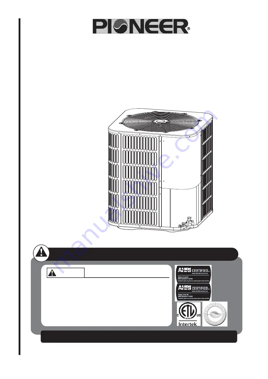
NOTE

: Appearance of unit may vary. 

INSTALLATION INSTRUCTIONS


18 SEER

SEER


DC INVERTER

Split System Heat Pump & Air Conditioner 

2-5 Tons

 - 

R410A

208~230 V. 1 Ph. 60 Hz.

Models:

YD024GMFI18MR2

YD036GMFI18MR2

YD048GMFI18MR2

YD060GMFI18MR2

Summary of Contents for YD024GMFI18MR2

Page 1: ... service or maintenance possibly resulting in fire electrical shock property damage personal injury or death RECOGNIZE THIS SYMBOL AS AN INDICATION OF IMPORTANT SAFETY INFORMATION DO NOT DESTROY THIS MANUAL Please read carefully and keep in a safe place for future reference by a serviceman NOTE Appearance of unit may vary INSTALLATION INSTRUCTIONS 18 SEER SEER DC INVERTER Split System Heat Pump Ai...

Page 2: ... AND LIQUID LINES 12 4 2 MAXIMUM LENGTH OF LINES 13 4 3 VERTICAL LIFT 13 5 0 EVACUATION 13 6 0 ELECTRICAL CONNECTIONS 14 6 1 GENERAL INFORMATION GROUNDING 14 6 2 FIELD CONNECTIONS POWER WIRING 14 6 3 REMOVING THE TOP PANEL AND MOTOR 15 7 0 CHECKING REFRIGERANT CHARGE 16 7 1 CHARGING BY LIQUID PRESSURE 16 7 2 CHARGING BY WEIGHT 16 7 3 FINAL LEAK TESTING 16 8 0 SYSTEM OPERATION 18 8 1 COMPRESSOR CRA...

Page 3: ...talla tion All phases of this installation must comply with NATIONAL STATE AND LOCAL CODES If additional information is required please contact your local distribu tor 3 WARNING Improper installation may create a condition where the operation of the product could cause personal injury or property damage Improper installation adjustment alteration service or maintenance can cause injury or property...

Page 4: ...100 feet 1 2 LIMITATIONS The unit should be installed in accordance with all National State and Local Safety Codes and the limitations listed below As soon as a unit is received it should be inspected for possible damage during transit If damage is evident the extent of the damage should be noted on the carrier s delivery receipt A separate request for inspection by the carrier s agent should be m...

Page 5: ... 24 15 16 633 33 3 16 843 33 3 16 843 36 36 AC HP 24 24 48 48 60 60 FIG 2 DIMENSIONS SUCTION LINE CONNECTION CONTROL WIRING 7 8 22 2mm KNOCKOUT 1 11 32 34 5mm LIQUID LINE CONNECTION SERVICE FITTING SERVICE FITTING POWER WIRING SEE DETAIL A DETAIL A HOLE 1 3 32 27 8mm NOTE GRILL APPEARANCE MAY VARY NOTES 1 AC Air Conditioner HP Heat Pump AIR DISCHARGE ALLOW 60 MINIMUM CLEARANCE SERVICE ACCESS ALLOW...

Page 6: ... avoid any possible wash out of the foundation When installing units on a roof the structure must be capable of supporting the total weight of the unit including a padded frame unit rails etc which should be used to minimize the transmission of sound or vibration into the conditioned space 3 3 ROOF INSTALLATION 3 4 UNIT PLACEMENT 1 Provide a base in the pre determined location 2 Remove the shippin...

Page 7: ...nt of the control box access panels and any other side requiring service Do not locate close to bedrooms as operational sounds may be objectionable Avoid locations near windows and similar areas where condensation and freezing defrost vapor can annoy a customer Position the outdoor unit a minimum of 12 from any wall or surrounding shrubbery to ensure adequate airflow Outdoor unit location must be ...

Page 8: ... being installed in areas where snow accumulation and prolonged below freezing temperatures occur Units should be elevated 3 12 inches above the pad or rooftop depending on local weather This additional height will allow drainage of snow and ice melted durIng defrost cycle prior to its refreezlng Ensure that drain holes in unit base pan are not obstructed preventing drainage of defrost water If po...

Page 9: ... brackets tighten concrete fasteners and self tapping screws See Fig 6 NOTE NOTE 1 One bracket for each side For extra stability 2 brackets for each side 2 Do not over tighten the concrete fastener to avoid weakening the concrete Step 1 Prior to installing clear pad of debris IMPORTANT Then cement pad must meet local codes and must be the proper thickness to accommodate fasteners Step 2 Center and...

Page 10: ...nimize the build up of liquid refrigerant in the suction line during long periods of shutdown 6 Pack a sealing material such as perma gum around refrigerant lines where they penetrate a wall to reduce vibration and to retain some flexibility Insulated Liquid Line Tape Sheet Metal Hanger optional Suggested Incorrect Fig 7 Tubing Hanger Fig 8 Underground Installation 10 Insulated Suction Line Fig 9 ...

Page 11: ...essure dry nitrogen is introduced into the tubing Only a small flow is necessary to displace air and prevent oxidation Precautions should be taken to prevent heat damage to service valve by wrapping a wet rag around it as shown in Fig 10 Also protect all painted surfaces insulation during brazing After brazing cool joint with wet rag 3 10 PRECAUTIONS DURING BRAZING SERVICE VALVE The valve can be o...

Page 12: ...Do not remove the flare caps from the service ports except when necessary for servicing the system 11 Release the refrigerant charge into the system Open both the liquid and suction valves by removing the plunger cap and with an hex wrench back out counter clockwise until valve stem just touches the chamfered retaining wall 12 Replace plunger cap finger tight then tighten an additional 1 12 turn 1...

Page 13: ... NOTE Excessively long refrigerant lines cause loss of equipment capacity 4 3 VERTICAL LIFT Keep the vertical lift to a minimum Use the following guidelines when installing the unit 1 DO NOT exceed the vertical lift as indicated on Table 3 2 It is recommended to use the smallest liquid line size permitted to minimize sys tem charge which will maximize compressor reliability 3 Table 3 may be used f...

Page 14: ...nnect switch to the unit 4 Route wires from disconnect through power wiring opening provided and into the unit control box 5 Install the proper size time delay fuses or circuit breaker and make the power supply connections 6 Energize the crankcase heater if equipped to save time by preheating the compres sor oil while the remaining installation is completed 6 2 FIELD CONNECTIONS POWER WIRING 6 0 E...

Page 15: ...to place fan cover unit on the ground as indicated in Fig 12 IMPROTANT NOTE Do not place or lean fan blades on ground or against surface Step 4 Remove fan motor by removing 5 16 nuts from cover Step 5 Remove fan blade from motor by removing 1 2 nut and place fan on the ground Step 6 Reverse removal process to reinstall the fan and motor IMPROTANT NOTE When connecting motor wires be sure to check m...

Page 16: ...tes 2 Measure OUTDOOR AMBIENT TEMPERATURE within 6 inches of coil 3 Measure SUCTION LINE PRESSURE AND TEMPERATURE 4 According to the superheat of suction line confirm that the TXV is working properly Usually the superheat is between 10 to 15 If not it should be adjusted 5 Find the TARGET LIQUID PRESSURE at the intersection between the SUCTION LINE PRESSURE and the OUTDOOR AMBIENT TEMPERATURE if fa...

Page 17: ...re length of the line from the servIce valve to the IDU 2 Enter the charge multiplier from column D 3 Muitply the total length of refrigerant tubing Line 1 tImes the value on step 2 Record the result on Line 3 of the worksheet 4 Locate the outdoor equipment size in column A Record the value shown In column c of Table 16 for Heat Pumps or Table 17 for Air conditioners 5 Add the values from step 3 a...

Page 18: ...y demands by manually adjusting the dial code as well so that to satisfy relative demands A working T3 Sensor is required for Operating protection high temp low temp Outdoor fan control cooling Heat pump only Defrost Heat pump only Ambient temp forecast Cooling only A working T4 Sensor is required for Heat pump only Operating condition permission Defrosting condition determination Outdoor fan cont...

Page 19: ...ust dial code to ON can enhance the ability of defrosting Manual defrosting The system must operate in heating mode Enter into this mode after 5 min when system starts It is suggest that stably running for 30 min then enter Press Force button and hold for at least 6s to enter into defrosting It is suggest that manual defrost time interval is 15min above Start if crankcase heating zone can satisfy ...

Page 20: ...tion Within 30 mins if 4 protection cycles occurs The system will be locked It will be restore after power cycle 8 4 SENSORS Start up conditions of defrost mode When JUMP switch is set to 1 See in Fig 11 the mode will start up in either of the two following conditions 1 Compressor operating when T4 is 28 4 F and T3 is 32 F last for 40 minutes 2 Compressor operating when T4 is 28 4 F and T3 is 32 F...

Page 21: ... 4 08 240 115 6 2 503 1 18 100 37 8 31 807 3 99 245 118 3 2 334 1 12 105 40 6 28 398 3 89 250 121 1 2 172 1 06 110 43 3 25 506 3 8 255 123 9 2 024 1 115 46 1 22 861 3 7 260 126 7 1 888 0 95 120 48 9 20 529 3 59 265 129 4 1 767 0 9 125 51 7 18 47 3 48 270 132 2 1 651 0 85 130 54 4 16 708 3 37 275 135 1 544 0 8 135 57 2 15 085 3 26 280 137 8 1 446 0 76 TEMP F TEMP C RESISTANCE kΩ VOLTS DC TEMP F TEM...

Page 22: ... 5 72 2 77 27 1 52 8 0 51 73 2 81 28 1 54 7 5 0 52 74 2 84 29 1 57 7 0 53 75 2 88 30 1 59 6 5 0 54 76 2 92 31 1 61 6 0 55 77 2 95 32 1 63 5 5 0 57 78 2 99 33 1 65 5 0 58 79 3 03 34 1 68 4 5 0 59 80 3 07 35 1 7 4 0 6 81 3 1 36 1 72 3 5 0 61 82 3 14 37 1 75 3 0 62 83 3 18 38 1 77 2 5 0 64 84 3 22 39 1 79 2 0 65 85 3 26 40 1 82 1 5 0 66 86 3 3 41 1 84 1 0 67 87 3 35 42 1 87 0 5 0 68 88 3 39 43 1 89 0...

Page 23: ...136 3 32 42 5 2 47 27 0 99 12 0 43 82 1 84 15 5 1 17 137 3 36 43 2 5 28 1 01 11 5 0 44 83 1 86 16 1 19 138 3 39 43 5 2 53 29 1 02 11 0 45 84 1 88 16 5 1 21 139 3 43 44 2 56 30 1 03 10 5 0 46 85 1 9 17 1 23 140 3 46 44 5 2 59 31 1 04 10 0 47 86 1 92 17 5 1 24 141 3 5 45 2 62 32 1 05 9 5 0 48 87 1 94 18 1 26 142 3 54 45 5 2 66 33 1 06 9 0 49 88 1 97 18 5 1 28 143 3 57 46 2 69 34 1 07 8 5 0 5 89 1 99...

Page 24: ...ure protection P2 Low pressure protection P3 frequency conversion over current protection P4 Air discharge overtemperature protection Cooling high pressure protection T3 pipe high temp P6 Compressor instant over current protection PH Compressor liquid return protection P8 DC fan typhoon protection After 2 min it w ill recover to normal status C3 T3 sensor loosely inserted error CE 5 P1 protections...

Page 25: ... data code pipe when pressing point check key shortly check key Display the next set of data when press the key once The display content is accordance with the sequence 2 There re 3 digits for LED The first digit is sequence only display units digit recycling display the second and third digits are values For example the 8th item is operating low pressure saturation temperature The 11th item is op...

Page 26: ... and cleaned regularly to assure proper drainage Assist owner with processing Warranty cards and or online registration CAUTION These units must be wired and installed in accordance with all National and Local Safety Codes CAUTION It is unlawful to knowingly vent release or discharge refrigerant into the open air during repair service maintenance or the final disposal of this unit When the system ...

Page 27: ... u o y t i c a p a c e v i t p a d A 1 4 W S d e s u t o N 4 H 5 H 6 H s e t u n i m 0 0 1 n i n o i t c e t o r p 4 P s e m i t 3 C H t l u a f r o s n e s e r u t a r e p m e t l a t n e m n o r i v n E b H g n i t a e H n i n o i t c e t o r p e r u s s e r p h g i h H H s e t u n i m 0 8 1 n i s e m i t 3 g n i n n u r t e W 5 E 7 E 6 E n o i t c e t o r p e g a t l o V d e v r e s e R t l u a...

Page 28: ...n m oto r CE High pressure protection C3 The T3 sensor is not seated fault F5 P2 P4 P3 Low pres s ure Pr o tection 5 tim e s P1 protecti oni n 15 0 minutes P1 P0 The exhau sttem p Ofthe comp Protection T5 P5 H igh T he t ub ete m p T3 pro tection T he I PM m odu lep rotectio n Wet runnin gstandby F3 Faul tdescri p tio n H8 P re s sure s enso r PS faul t 2 times E 6 protection in 10 minutes Hig hpr...

Page 29: ...ring terminal connect a reactor betw een 2 and 3 15 Spot check button 4 Defrosting function dial codeSW5 16 Forced operation button 5 Pressure sensor port 17 Reserved 6 Air discharge temp sensor port 18 Nixie tube display 7 Outdoor temp sensor port HP only 19 Fan control port 8 Condenser temp sensor port 20 Crankcase heating zone control terminal 9 Radiator temp sensor port 21 Short w ire 10 High ...

Page 30: ... 451 477 209 228 247 267 286 306 328 350 373 398 424 450 476 206 226 246 266 285 305 327 349 371 397 423 449 474 207 226 245 264 284 304 326 348 370 396 422 448 473 205 224 244 263 283 302 324 347 369 394 420 446 472 204 223 242 262 281 301 323 345 367 393 419 445 471 201 221 241 261 280 300 322 344 366 392 418 444 469 202 221 240 259 279 298 321 343 365 390 416 442 468 200 219 239 258 278 297 319...

Page 31: ...88 307 330 353 376 403 429 455 481 211 230 249 268 286 305 328 351 374 401 427 453 479 209 228 247 266 284 303 326 349 372 399 425 451 477 207 226 245 264 282 301 324 347 370 397 423 449 475 205 224 243 262 280 299 322 345 368 395 421 447 473 203 222 241 260 278 297 320 343 366 393 419 445 471 201 220 239 258 276 295 318 341 364 391 417 443 469 199 218 237 256 274 293 316 339 362 389 415 441 467 1...

Page 32: ...nit Operational and Checkout Procedures To obtain proper performance all units must be operated and charge adjustments made in accordance with procedures found in the Service Facts of the Outdoor Unit 7 Be sure that a return air filter is installed 8 Operate complete system in each mode to verify proper performance Verify operation of supplementary electric heater TABLE 9 Operational And Checkout ...

Page 33: ...o normal when electricity grid is normal Replace the mainboard No H4 P6 Compressor instant over current protection Diagnosis Handling Check if ball valves are open Yes Check whether the compressor wiring is normal Yes Whether compressor insulation resistance is below 100kΩ Yes Whether compressor coil is broken No Restart to make sure that high and low pressure difference is within 0 2MPa Yes Air d...

Page 34: ...ether the fan and blade can normally operate Yes Whether the duct including radiator is blocked by debris No Whether resistance of Tf is in the range of TABLE2 Yes Re insert Tf power off and restart to see if there s the same error Fix the radiator If radiator is damaged replace it Yes Clean radiator duct Yes Replace motor or blade No No Replace Tf No Troubleshoot surrounding influence to the duct...

Page 35: ...min then the refrigerant system is error No Replace the mainboard Yes H5 P2 Low pressure protection Diagnosis Handling Whether gas valve and liquid valve are open Yes Whether indoor side is normal valve is blocked or radiator is sheltered fan is stopped No Unplug low pressure sensor LPC to see if resistance is 0 Ω 0 Ω is normal No Connect a pressure gage to gas valve and restart to test if pressur...

Page 36: ...round T3 T4 No Whether pressure switch HPC is in error whether the fan doesn t operate No Power off and restart to see if there s the same error Fix the sensor to the heat exchanger to U pipe and power on to restart Yes Wiring according to the nameplate correctly and power on to restart No Exclude influence by the nearby heat sources Yes Replace the mainboard Yes Replace the fan and pressure switc...

Page 37: ...p protection Diagnosis Handling Whether gas valve and liquid valve are open Yes Whether T3 T5 are abnormal No Check whether outdoor unit fan is abnormal and whether the outdoor heat exchanger is blocked by debris No Whether there s short circuit in air outlet and inlet side when the ambient temp is high No Restart to see if there s the same error Open gas valve and liquid valve No Replace sensors ...

Page 38: ...202000172553 MD14IU 017AW Parker Davis HVAC International Inc 2250 NW 102 PLACE DORAL FLORIDA 33172 USA Phone 305 513 4488 Fax 305 513 4499 ...

Reviews: